dashboard HONDA CIVIC 2002 7.G Owners Manual
[x] Cancel search | Manufacturer: HONDA, Model Year: 2002, Model line: CIVIC, Model: HONDA CIVIC 2002 7.GPages: 1139, PDF Size: 28.19 MB
Page 1084 of 1139
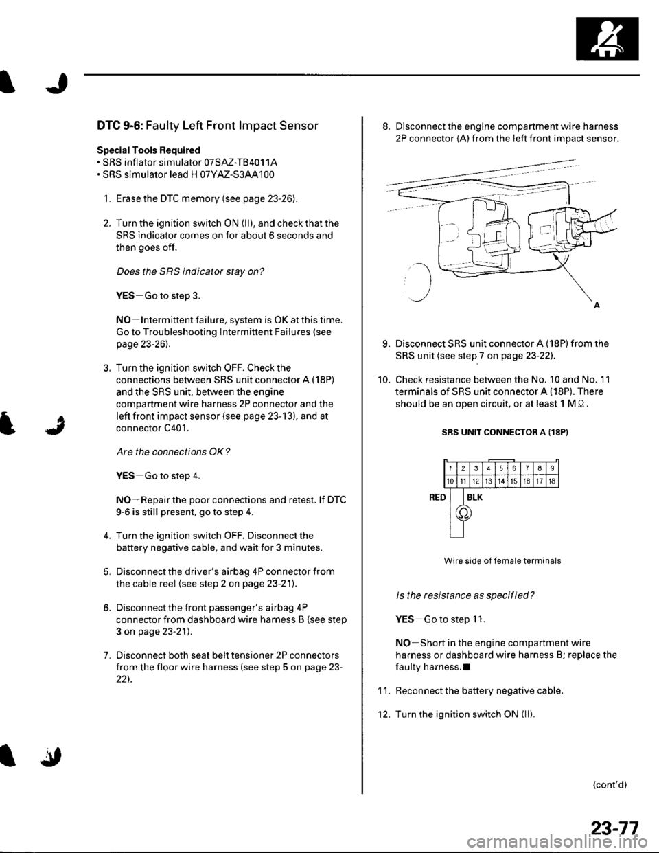
DTC 9-6: Faulty Left Front lmpact Sensor
Special Tools Required. SRS inflator simulator 07SAZ-TB4011A. SRS simulator lead H 07YM-S3AA100
1. Erase the DTC memory (see page 23-26).
2. Turn the ignition switch ON (ll), and check that the
SRS indicator comes on for about 6 seconds and
then goes off.
Does the SRS indicator stay on?
YES-Go to step 3.
NO Intermiftent failure, system is OK at this time.
Go to Troubleshooting Intermittent Failures (see
page 23-26).
3. Turn the ignition switch OFF. Check the
connections between SRS unit connector A (18P)
and the SRS unit. between the engine
compartment wire harness 2P connector and the
left front impact sensor {see page 23-13), and at
connector C401.
Are the connections OK?
YES Go to step 4.
NO-Repair the poor connections and retest. lf DTC
9-6 is still present, go to step 4.
Turn the ignition switch OFF. Disconnect the
battery negative cable. and wait for 3 minutes.
Disconnect the driver's airbag 4P connector from
the cable reel (see step 2 on page 23-21).
Disconnect the front passenger's airbag 4P
connector from dashboard wire harness B {see step
3 on page 23-21).
Disconnect both seat belt tensioner 2P connectors
from the floor wire harness (see step 5 on page 23-
22).
7.
9.
10.
8. Disconnect the engine compartment wire harness
2P connector {A) from the left front impact sensor.
Disconnect SRS unit connector A {18P) from the
SRS unit (see step 7 on page 23-22J.
Check resistance between the No. 10 and No. 11
terminals of SRS unit connector A (18P). There
should be an oDen circuit. or at least 1 M 0 .
SRS UNIT CONNECTOR A (18PI
Wire side of female terminals
ls the resistance as specitied?
YES Go to step 1 1.
NO-Short in the engine companment wire
harness or dashboard wire harness B; replace the
faulty harness.I
Reconnect the battery negative cable.
Turn the ignition switch ON { ll).
{cont'd}
RED
11.
12.
2356789
10tl1Zt315161718
I
T
ILK
23-77
Page 1085 of 1139
sRs
DTC Troubleshooting (cont'dl
13. Check voltage between the No. 10 terminal of SRS
unit connector A (18P) and body ground. There
shouid be 'l V or less.
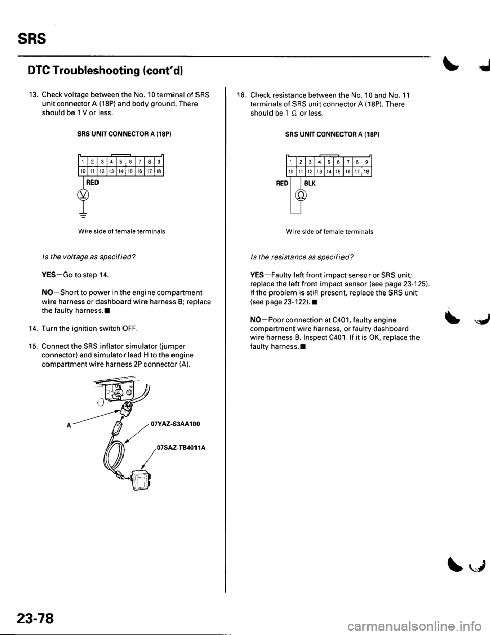
SRS UNIT CONNECTOR A {,I8P)
12378I
101112l3t4151611t6
RED
Wire side oI female terminals
ls the voltage as specitied?
YES-Go to step 14.
NO-Short to power in the engine compartment
wire harness or dashboard wire harness B; replace
the faulty harness.l
Turn the ignition switch OFF.
Connect the SRS inflator simulator (jumper
connector) and simulator lead H to the engine
compartment wire harness 2P connector (A).
07YAZ-S3AA100
07SAZ-TB,O11A
14.
t5.
23-78
\."r1
16. Check resistance between the No. 10 and No. 11
terminals of SRS unit connector A (18P). There
should be 1 0 or less.
SRS UNIT CONNECTOR A Il8PI
Wire side of female terminals
ls the rcsistance as specified?
YES Faulty left front impact sensor or SRS unit;
replace the left front impact sensor (see page 23-125).
lf the problem is still present, replace the SRS unit(see page 23-122).1
NO-Poor connection at C401, faulty engine
compartment wire harness, or faulty dashboard
wire harness B. Inspect C401. lf it is OK, replace the
faulty harness.l
= \y,
Page 1086 of 1139
)
t
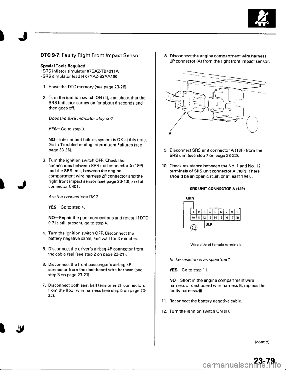
DTC 9-7: Faulty Right Front lmpact Sensor
Special Tools Bequired. SRS inflator simulator 07SAZ-TB4011A. SRS simulator lead H 07YM-S3AA100
1. Erase the DTC memory {see page 23-26).
2. Turn lhe ignition switch ON {ll), and checkthatthe
SRS indicator comes on for about 6 seconds and
then goes off.
Does the SRS indicator stay on?
YES-Go to step 3.
NO Intermittent failure, system is OK at this time.
Go to Troubleshooting Intermittent Failures (see
page 23-26).
3. Turn the ignition switch OFF. Check the
connections between SRS unit connectorA (18P)
and the SRS unit, between the engine
compartment wire harness 2P connector and the
right front impact sensor (see page 23-13), and at
connector C401.
Are the connections OK?
YES-Go to step 4.
NO Repair the poor connections and retest. lf DTC
9-7 is still present, go to step 4.
Turn the ignition switch OFF. Disconnect the
battery negative cable, and wait for 3 minutes.
Disconnect the driver's airbag 4P connector from
the cable reel {see step 2 on page 23-21).
Disconnect the front passenger's airbag 4P
connector from the dashboard wire harness (see
step 3 on page 23-21).
Disconnect both seat belt tensioner 2P connectors
from the floor wire harness (see step 5 on page 23-
22).
4.
5.
7.
I
'10.
Disconnect the engine compartment wire harness
2P connector (A) from the right front impact sensor.
Disconnect SRS unit connector A (18P) from the
SRS unit (see step 7 on page 23-221.
Check resistance between the No. 1 and No. 12
terminals of SRS unit connector A (18P). There
should be an open circuit, or at least 1 M 0.
SRS UNIT CONNECTOR A (18PI
GRN
11.
Wire side ol female terminals
ls the resistance as specified?
YES Go to step 11.
NO-Short in the engine companment wire
harness or dashboard wire harness B; replace the
faulty harness,I
Reconnect the battery negative cable.
Turn the ignition switch ON (ll).
(cont'd)
IF!-t1t2)l
Irolrlr
56I6
13161718
SLK
23-79
Page 1087 of 1139
sRs
DTC Troubleshooting (cont'd)
13. Check voltage between the No. 1terminal ofSRS
unit connector A (18P) and body ground. There
should be 1 V or less.
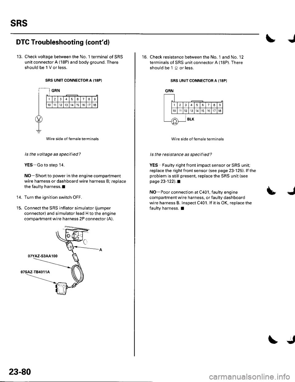
SRS UNIT CONNECTOR A I18P}
Wire side of female terminals
ls the voltage as specified?
YES Go to step 14.
NO-Short to power in the engine compartment
wire harness or dashboard wire harness B; replace
the faulty harness.l
Turn the ignition switch OFF.
Connect the SRS inflator simulator (jumper
connector) and simulator lead H to the engine
compartment wire harness 2P connector (A).
14.
07YAZ-S3AA100
23-80
16. Check resistance between the No. 1 and No. '12
terminals of SRS unit connector A (18P). There
should be 1 O or less.
SRS UNIT CONNECTOR A {18P)
GRN
Wire side of female terminals
ls the resistance as specitied?
YES Faulty right front impact sensor or SRS unit;
replace the rightfront sensor {see page 23-125). lfthe
problem is still present, replace the SRS unit (see
page 23-1221.a
NO- Poor connection at C401, faulty engine
compartment wire harness, or faulty dashboard
wire harness B. lnspect C401. lf it is OK, replace the
faulty harness, I
LJ
J_lr12lr
tE.]I
/A
56789
t311r51611t6
BLK
Page 1107 of 1139
sRs
DTC Troubleshooting (cont'd)
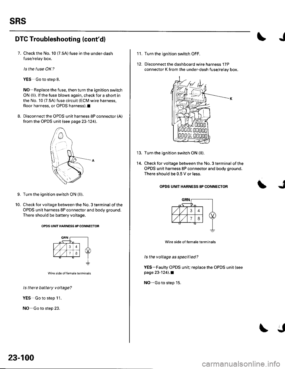
7. Check the No. 10 (7.5A)fuse in the under-dash
fuse/relay box.
ls the f use OK?
YES Go to step 8.
NO Replace the fuse, then turn the ignition switch
ON (ll). lf the fuse blows again, check for a short in
the No. 10 {7.5A) fuse circuit (ECM wire harness.
floor harness, or OPDS harness).1
8. Disconnect the OPDS unit harness 8P connector (A)
from the OPDS unit (see page 23-124).
Turn the ignition switch ON (ll).
Check for voltage between the No. 3 terminal of the
OPDS unit harness 8P connector and body ground.
There should be battery voltage.
OPDS UNtT HARNESS 8P CONNECTOR
Wire side of female terminals
ls there battety voltage?
YES Go to step 11.
NO Go to step 23.
9.
10.
23-100
11.
12.
14.
Turn the ignltion switch OFF.
Disconnect the dashboard wire harness 17P
connector K from the under-dash fuse/relay box,
Turn the ignition switch ON (ll).
Check for voltage between the No. 3 terminal of the
OPDS unit harness 8P connector and body ground.
There should be 0.5 V or less.
OPDS UNIT HABNESS 8P CONNECTOR
Wire side of lemale terminals
ls the voltage as specitied?
YES-Faulty OPDS unit; replace the OPDS unit (see
page 23-124) .a
NO-Go to step 15.
Page 1108 of 1139
)
t5.
17.
18.
Turn the ignition switch OFF.
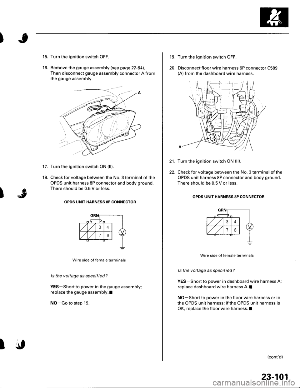
Remove the gauge assembly (see page 22-64).
Then disconnect gauge assembly connector A from
the gauge assembly.
Turn the ignition switch ON (ll).
Check for voltage between the No. 3 terminal of the
OPDS unit harness 8P connector and body ground.
There should be 0.5 V or less.
OPOS UNIT HARNESS 8P CONNECTOR
Wire side of female terminals
ls the voltage as specified?
YES Short to power in the gauge assembly;
replace the gauge assembly.l
NO Go to step 19.
)
A
\,I
19.
20.
22.
Turn the ignition switch OFF.
Disconnect floor wire harness 6P connector C509(A)from the dashboard wire harness.
Turn the ignition switch ON (ll).
Check for voltage between the No. 3 terminal of the
OPDS unit harness 8P connector and body ground.
There should be 0.5 V or less.
OPDS UNIT HARNESS 8P CONNECTOB
Wire side o{ female terminals
ls the voltage as specified?
YES Short to power in dashboard wire harness A;
replace dashboard wire harness A.l
NO-Short to power in the floor wire harness or in
the OPDS unit harness; if the OPDS unit harness is
OK, replace the floor wire harness.I
(cont'd)
23-101
Page 1109 of 1139
sRs
23.
24.
DTC Troubleshooting (cont'dl
Turn the ignition switch OFF.
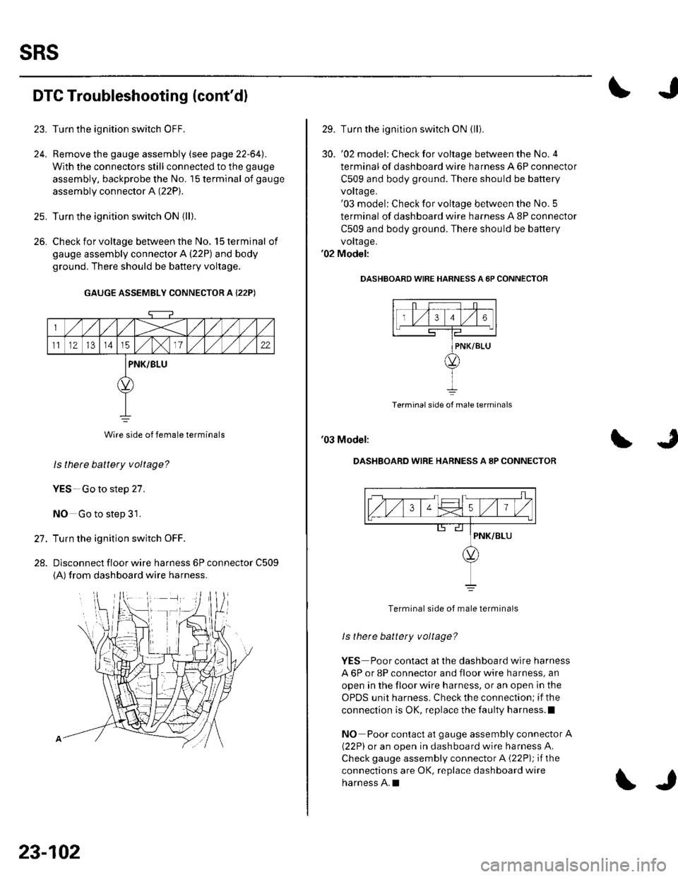
Remove the gauge assembly (see page 22-64l,.
With the connectors still connected to the gauge
assembly, backprobe the No. '15 terminal of gauge
assembly connector A (22P).
Turn the ignition switch ON {ll).
Check for voltage between the No. 15 terminal of
gauge assembly connector A {22P) and body
ground. There should be battery voltage.
GAUGE ASSEMBLY CONNECTOR A {22P)
Wire side of female terminals
ls thete battery voltage?
YES-Go to step 27.
NO Go to step 31.
Turn the ignition switch OFF.
Dlsconnect floor wire harness 6P connector C509
{A) from dashboard wire harness.
26.
27.
28.
23-102
\J
29. Turn the ignition switch ON (lli
30. '02 model: Checkforvoltage between the No.4
terminal of dashboard wire harness A 6P connector
C509 and body ground. There should be battery
vorlage.'03 model: Check for voltage between the No. 5
terminal of dashboard wire harness A 8P connector
C509 and body ground. There should be battery
vollage.'02 Model:
OASHBOARD WIRE HARNESS A 6P CONNECTOF
Terminal side of male terminals
'03 Model:
DASHBOARD WIRE HARNESS A 8P CONNECTOR
Terminal side of male terminals
ls there battety voltage?
YES Poor contact at the dashboard wire harness
A 6P or 8P connector and floor wire harness, an
open in the floor wire harness, or an open in the
OPDS unit harness. Check the connection; if the
connection is OK, replace the faulty harness.l
NO Poor contact at gauge assembly connector A
{22P) or an open in dashboard wire harness A.
Check gauge assembly connector A {22P); if the
connections are OK, replace dashboard wire
harness A.I
Page 1110 of 1139
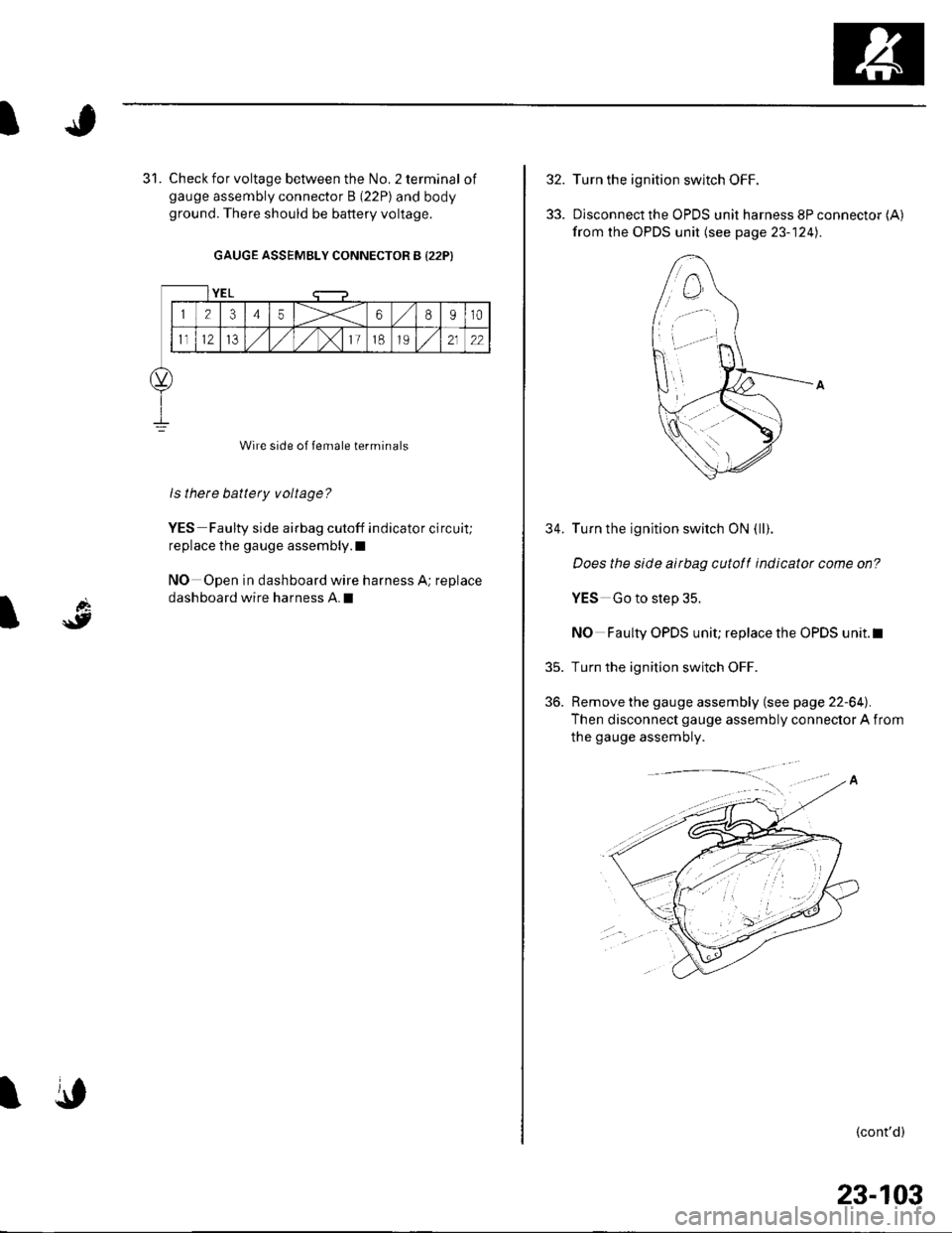
Check for voltage between the No. 2 terminal ofgauge assembly connector B (22P) and bodyground. There should be battery voltage.
GAUGE ASSEMBLY CONNECTOR B {22P)
Wire side of female terminals
ls there battery voltage?
YES Faulty side airbag cutoff indicator circuit;
replace the gauge assembly.l
NO Open in dashboard wire harness A; replace
dashboard wire harness A.I
YEL
12345X68910
1t12IJ,/1,/1,/)112122
\,
32.
33.
35.
36.
34.
Turn the ignition switch OFF.
Disconnect the OPDS unit harness 8P connector (A)
from the OPDS unit (see page 23- 124).
Turn the ignition switch ON (ll).
Does the slde airbag cutotf indicator come on?
YES Go to step 35.
NO Faulty OPDS unit; replace the OPDS unit.l
Turn the ignition switch OFF.
Remove the gauge assembly (see page 22-64).
Then disconnect gauge assembly connector A from
the gauge assembly.
(cont'd)
23-103
Page 1111 of 1139
sRs
DTG Troubleshooting (cont'dl
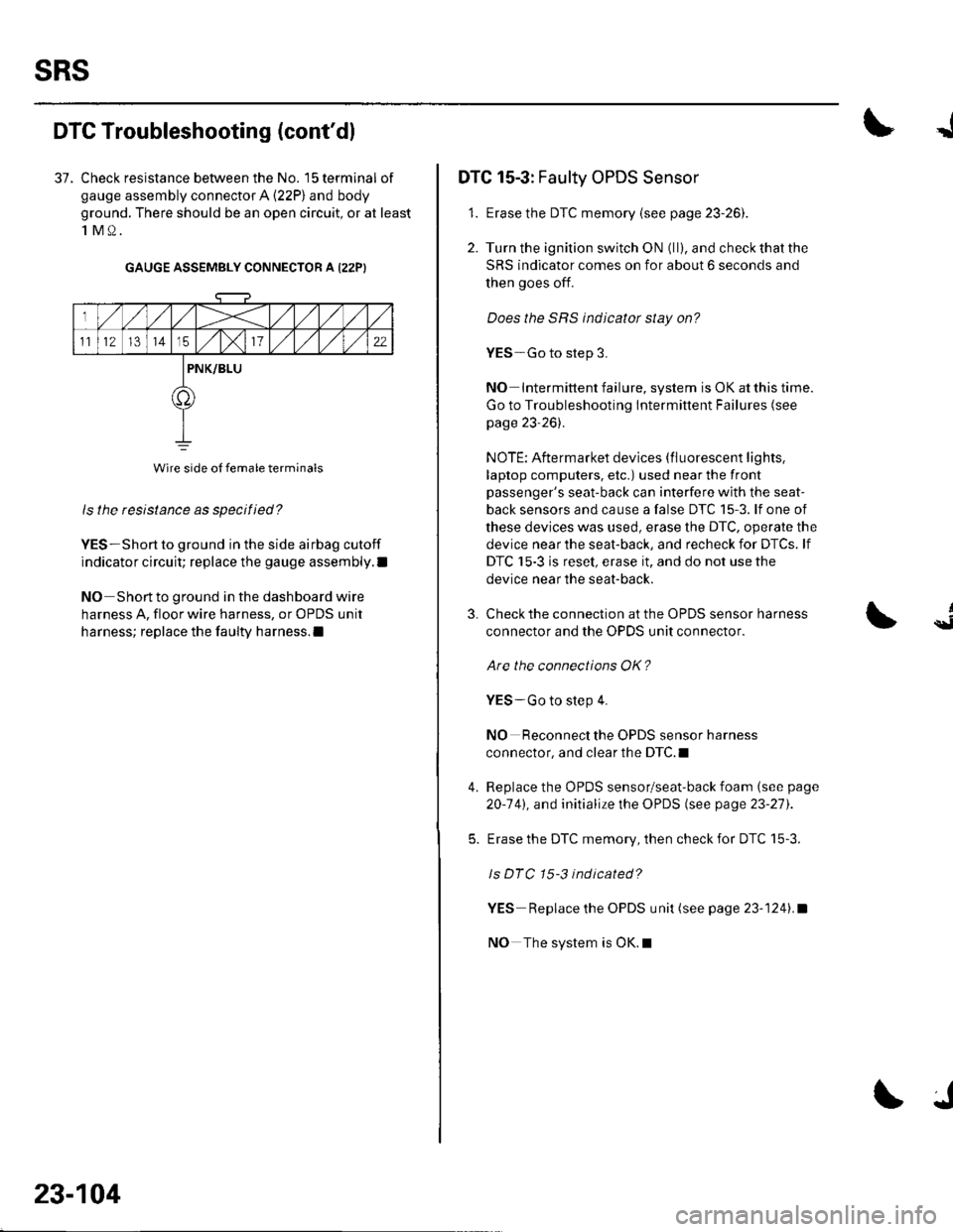
37. Check resistance between the No. 15 terminal of
gauge assembly connector A (22P) and body
ground. There should be an open circuit, or at least
1M0.
GAUGE ASSEMBLY CONNECTOR A I22PI
ls the resistance as specified?
YES-Short to ground in the side airbag cutoff
indicator circuit; replace the gauge assembly.l
NO Short to ground in the dashboard wire
harness A, floor wire harness, or OPDS unit
harness; replace the faulty harness.l
Wire side of female terminals
23-104
J
DTC 15-3: Faulty OPDS Sensor
1. Erase the DTC memory {see page 23-261.
2. Turn the ignition switch ON (ll), and check that the
SRS indicator comes on for about 6 seconds and
then goes off.
Does the SRS indicator stay on?
YES-Go to step 3.
NO Intermittent failure, system is OK at this time.
Go to Troubleshooting Intermittent Failures (see
page 23-26).
NOTE: Aftermarket devices (fluorescent lights,
laptop computers, etc.) used near the front
passenger's seat-back can interfere with the seat-
back sensors and cause a false DTC 15-3. lf one of
these devices was used, erase the DTC, operate the
device near the seat-back, and recheck for DTCs. lf
DTC 15-3 is reset, erase it, and do not use the
device near the seat-back.
3.
4.
Check the connection at the OPDS sensor harness
connector and the OPDS unit connector.
Are the connections OK?
YES-Go to step 4.
NO Reconnect the OPDS sensor harness
connector, and clear the DTC.I
Replace the OPDS sensor/seat-back foam (see page
20-141, and initialize the OPDS (see page 23-27).
Erase the DTC memory, then check for DTC 15-3.
ls DTC 15-3 indicated?
YES Replace the OPDS unit (see page 23-1241.a
NO The system is OK.l
{
Page 1112 of 1139
I
d
\9I
SRS Indicator Circuit Troubleshooting
The SRS Indicator Doesn't Come On
1. Turn the ignition switch ON (ll), and see if the otherindicators come on {brake system, etc).
Do the other indicators come on?
YES Go to step 2.
NO-Go to step 8.
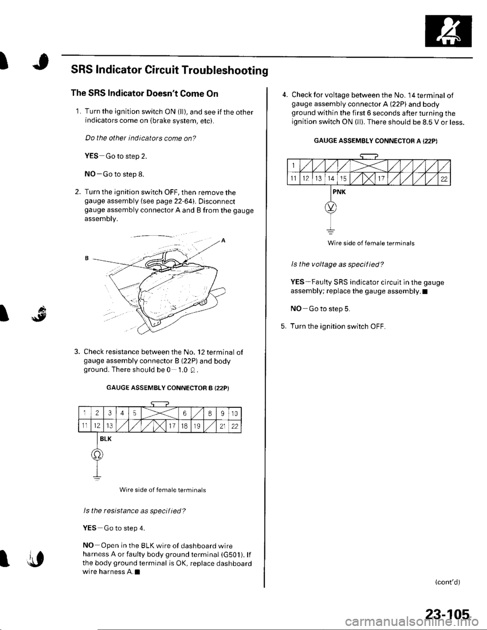
2. Turn the ignition switch OFF, then remove thegauge assembly {see page 22-641. Disconnectgauge assembly connector A and B from the gauge
assembly.
Check resistance between the No. 12 terminal ofgauge assembly connector B (22P) and bodyground. There should be 0 1.0 Q.
GAUGE ASSEMBLY CONNECTOR B I22PI
12345X68910
1112l3/)x111B2122
BLK
o.
Wire side of female terminals
Is the resistance as specified?
YES Go to step 4.
NO Open in the BLK wire of dashboard wire
harness A or faulty body ground terminal (G501). lf
the body ground terminal is OK, replace dashboard
wire harness A.Il{,
23-105
4. Check for voltage between the No. l4terminal ofgauge assembly connector A (22P) and bodyground within the first 6 seconds after turning the
ignition switch ON (ll). There should be 8.5 V or less.
GAUGE ASSEMBLY CONNECTOR A I22PI
Wire side of female terminats
Is the voltage as specified?
YES-Faulty SRS indicator clrcuit in the gauge
assembly; replace the gauge assembly.I
NO-Go to step 5.
Turn the ignition switch OFF.
(cont'd)