dashboard HONDA CIVIC 2002 7.G Workshop Manual
[x] Cancel search | Manufacturer: HONDA, Model Year: 2002, Model line: CIVIC, Model: HONDA CIVIC 2002 7.GPages: 1139, PDF Size: 28.19 MB
Page 1113 of 1139
sRs
6.
SRS Indicator Circuit Troubleshooting (cont'dl
7.
Disconnect SRS unit connector C (8P) from the SRS
unit {see step 7 on page 23-22).
Disconnect gauge assembly connector A (22P).
Connect a voltmeter between the No, l4terminal of
gauge assembly connector A (22P) and body
ground. Turn the ignition switch ON (ll), and
measure voltage. There should be 0.5 V or less.
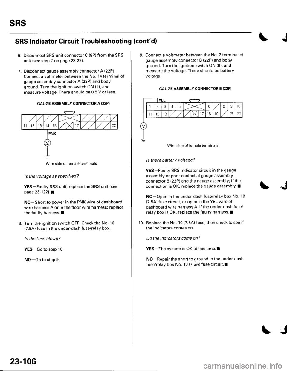
GAUGE ASSEMBLY CONNECTOR A {22P)
Wire side of female terminals
ls the voltage as specitied?
YES-Faulty SRS unit; replace the SRS unit (see
page 23-'l22l.a
NO-Short to power in the PNK wire of dashboard
wire harness A or in the floor wire harness; replace
the faulty harness.l
L Turn the ignition switch OFF. Check the No. 10
{7.5A)fuse in the under-dash fuse/relay box.
ls the tuse blown?
YES-Go to step 10.
NO Go to step 9.
23-106
J
9. Connect a voltmeter between the No.2 terminal of
gauge assembly connector B (22P) and body
ground. Turn the ignition switch ON (ll), and
measure the voltage. There should be battery
voltaqe.
GAUGE ASSEMBLY CONNECTOR B (22P}
YEL
12345X68910
ll12,/ ,/,/x11o2122
Wire side of female terminals
ls therc battery voltage?
YES Faulty SRS indicator circuit in the gauge
assembly or poor contact at gauge assembly
connector B (22P) and the gauge assembly; if the
connection is OK, replace the gauge assembly.l
NO Open in the under-dash fuse/relay box No. 10
(7.5A) fuse circuit, or open in the YEL wire of
dashboard wire harness A. lf the under-dash fuse/
relay box is OK, replace lhe faulty harness.l
Replace the No. 10 (7.5A) fuse, then check to see if
the indicators comes on.
Do the indicators come on?
YES The system is OK at thls time.l
NO Repair the short to ground in the under-dash
fuse/relay box No. 10 (7.5A)fuse circuit.l
10.
Page 1115 of 1139
sRs
from the under-dash fuse/relav bor.
11.
18.
SRS Indicator Circuit Troubleshooting (cont'd)
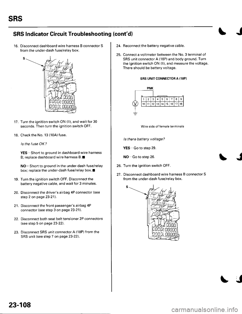
'16. Disconnect dashboard wire harness B connector S
Turn the ignition switch ON {ll), and wait for 30
seconds. Then turn the ignition switch OFF,
Check the No. 13 (10A) fuse.
ls the f use OK?
YES Short to ground in dashboard wire harness
B; replace dashboard wire harness B.I
NO-Short to ground in the under-dash fuse/relay
box; replace the under-dash fuse/relay box.l
Turn the ignition switch OFF. Disconnect the
battery negative cable, and wait for 3 minutes.
Disconnect the driver's airbag 4P connector (see
step 2 on page 23-2'l).
Disconnect the front passenger's airbag 4P
connector (see step 3 on page 23-21).
Disconnect both seat belt tensioner 2P connectors
(see step 5 on page 23-22).
Disconnect SRS unit connector A (18P) from the
SRS unit (see step 7 on page 23-22).
19.
20.
21.
22.
23-108
24.Beconnect the battery negative cable.
Connect a voltmeter between the No. 3 terminal of
SRS unit connector A (18P) and body ground. Turn
the ignition switch ON (ll), and measure the voltage.
There should be baftery voltage.
SRS UNIT CONNECTOR A (18PI
Wire side of female terminals
ls there battery voltage?
YES Go to step 29.
NO Go to step 26.
Turn the ignition switch OFF.
Disconnect dashboard wire harness B connector S
26.
27.
PNK
from the under-dash fuse/relav box.
Page 1116 of 1139
I
28. Check resistance between the No. 3 terminal of
SRS unit connector A (18P) and the No. 2 terminal
of dashboard wire harness B connector S. There
should be 0 1.0 0.
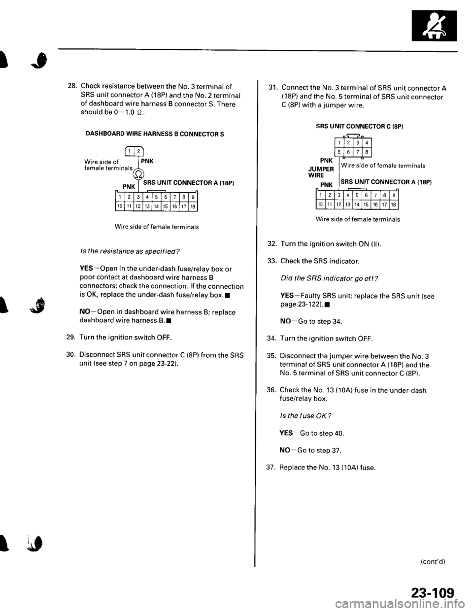
DASHBOARD WIRE HARNESS B CONNECTOR S
Wire side offemale term
l2
rna lsPNK
a,
PNK T SRS uNrr
l23578I
101112l314151611l8
CONNECTOR A I18P)
I
Wire side of female terminals
ls the rcsistance as specified?
YES-Open in the under-dash fuse/relay box orpoor contact at dashboard wire harness B
connectors; check the connection. lf the connection
is OK, replace the under-dash fuse/relay box.l
NO-Open in dashboard wire harness B; replace
dashboard wire harness B.I
Turn the ignition switch OFF.
Disconnect SRS unit connector C {8P) from the SRS
unit (see step 7 on page 23-22],.
29.
30.
I
SRS UNIT CONNECTOR C I8P}
31. Connect the No. 3 terminal ofSRS unitconnectorA(18P) and the No. 5 terminal of SRS unit connector
C (8P)with a jumper wire.
PNK
JUMPERWIRE
PNK
Wire side of female terminals
SRS UNIT CONNECTOR A I18P)
Wire side of temale terminals
32. Turn the ignition switch ON (llf .
33. Check the SRS indicator.
Did the SRS indicator go off?
YES Faulty SRS unit; replace the SRS unit (see
page 23-122l.a
NO-Go to step 34.
34. Turn the ignition switch OFF.
35. Disconnect the jumper wire between the No. 3
terminal of SRS unit connector A (18P) and the
No. 5 terminal of SRS unit connector C (8P).
36. Check the No. 13 (10A)fuse in the under,dash
fuse/relay box.
ls the f use OK?
YES Go to step 40.
NO Go to step 37.
37. Replace the No. 13 {10A)fuse.
(cont'd)
23-109
Page 1117 of 1139
sRs
39.
SRS lndicator Gircuit Troubleshooting (cont'dl
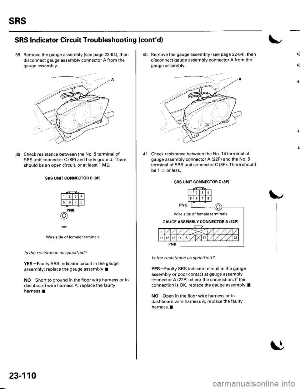
38. Remove the gauge assembly (see page 22-64), then
disconnect gauge assembly connector A from the
gauge assemDly,
Check resistance between the No. 5 terminal of
SRS unit connector C (8P) and body ground. There
should be an ooen circuit, or at least 1 fM Q ,
SRS UNIT CONNECTOR C {8PI
Wire side of lemale terminals
ls the resbtance as specitied?
YES-Faulty SRS indicator circuit in the gauge
assembly; replace the gauge assembly.I
NO Short to ground in the floor wire harness or in
dashboard wire harness A; replace the faulty
harness.l
23-110
40. Remove the gauge assembly (see page 22-64), then
disconnect gauge assembly connector A from the
gauge assembly.
Check resistance between the No. 14 terminal of
gauge assembly connector A (22P) and the No.5
terminal of SRS unit connector C (8P). There should
be 'l 0 or less,
41.
SRS UNIT CONNECTOR C (8P}
ls the resistance as specitied?
YES Faulty SRS indicator circuit in the gauge
assembly or poor contact at gauge assembly
connector A (22P); check the connection. lf the
connection is OK, replace the gauge assembly,I
NO Open in the floor wire harness or in
dashboard wire harness A; replace the faulty
harness. !
Wire side of lemale terminals
GAUGE ASSEMBLY CONNECTOR A I22P)
Page 1121 of 1139
sRs
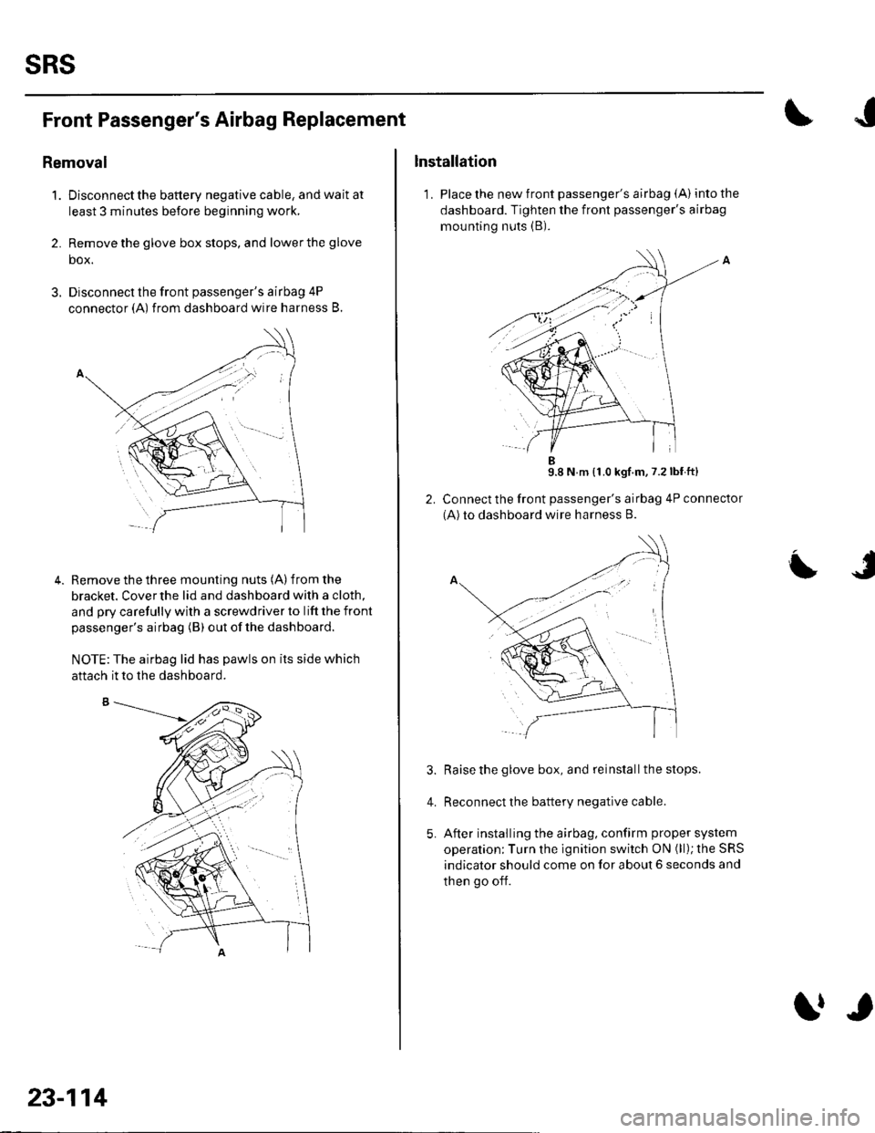
Front Passenger's Airbag Replacement
Removal
1. Disconnectthe battery negative cable, and wait at
least 3 minutes before beginning work,
2. Remove the glove box stops, and lower the glove
box.
3. Disconnect the front passenger's airbag 4P
connector (A) from dashboard wire harness B.
Remove the three mounting nuts (A) from the
bracket. Cover the lid and dashboard with a cloth,
and pry carefully with a screwdriver to lift the front
passenger's airbag (B) out ofthe dashboard.
NOTE:The airbag lid has pawls on its side which
4.
aftach it to the dashboard.
23-114
trr
Installation
1. Place the new front passenger's airbag (A) into the
dashboard. Tighten the front passenger's airbag
mounting nuts (B).
9.8 N m {1.0 kgf.m,7.2lbf ft}
Connect the front passenger's airbag 4P connector
(A)to dashboard wire harness B.
Raise the glove box, and reinstall the stops.
Reconnect the battery negative cable.
After installing the airbag, confirm proper system
operation; Turn the ignition switch ON (ll); the SRS
indicator should come on for about 6 seconds and
then go off.
L
4.
Page 1123 of 1139
sRs
Airbag Disposal
Special Tool Required
Deployment tool 07HAz-SG00500
Before scrapping any airbags, side airbags, seat belt
tensioners, or seat belt buckle tensioners (including
those in a whole vehicle to be scrapped), the airbags,
side airbags, seat belt tensioners, or seat belt buckle
tensioners must be deployed. lf the vehicle is still within
the warranty period, the Honda District Service
Manager must give approval and/or special instruction
before deploying the airbags, side airbags, seat belt
tensioners, or seat belt buckle tensioners. Only after the
airbags, side airbags, seat belt tensioners, or seat belt
buckle tensioners have been deployed (as the result of
vehicle collision, for example), can they be scrapped.
lf the airbags, side airbags, seat belt tensioners, and
seat belt buckle tensioners appear intact (not deployed),
treat them with extreme caution. Follow this Drocedure.
Deploying Airbags in the Vehicle
lf an SRS equipped vehicle is to be entirely scrapped, its
airbags, side airbags. seat belt tensioners. and seat belt
buckle tensioners should be deoloved while still in the
vehicle. The airbags, side airbags, seat belttensioners,
and seat belt buckle tensioners should not be
considered as salvageable parts and should never be
installed in another vehicle.
1. Turn the ignition switch OFF, then disconnect the
battery negative cable, and wait at least 3 minutes.
2. Confirm that each airbag, side airbag, or seat belt
tensioner is securely mounted.
3. Conf irm that the specia I tool isfunctioning properly
by following the check procedure on the tool label.
23-116
$J
Driver's Airbag:
4. Remove the access panel f rom the steering wheel,
then disconnect the driver's airbag 4P connector
from the cable reel (see step 2 on page 23-21).
Front Passenger's Airbag:
5. Lowerthe glove box, then disconnectthe front
passenger's airbag 4P connector from dashboard
wire harness B (see step 3 on page 23-211.
Side Airbag:
6. Disconnect the side airbag 2P connectors from the
floor wire harness (see step 4 on page 23-211.
Seat belt tensioner:
7. Disconnect the seat belt tensioner 2P connectors
from the floor wire harness {see step 5 on page 23-
22). Pull the seat belt out all the way, and cut it off.
Seat belt buckle tensioner:
8, Disconnect the seat belt buckle tensioner 4P
connectors from the floor wire harness (see step 6
on page 23-221.
Page 1126 of 1139
)
3.
4.
Cable Reel Replacement
Removal
1. Make sure the front wheels are aligned straight
ahead.
Disconnect the battery negative cable, and wait at
least 3 minutes.
Remove the driver's airbag {see page 23-113).
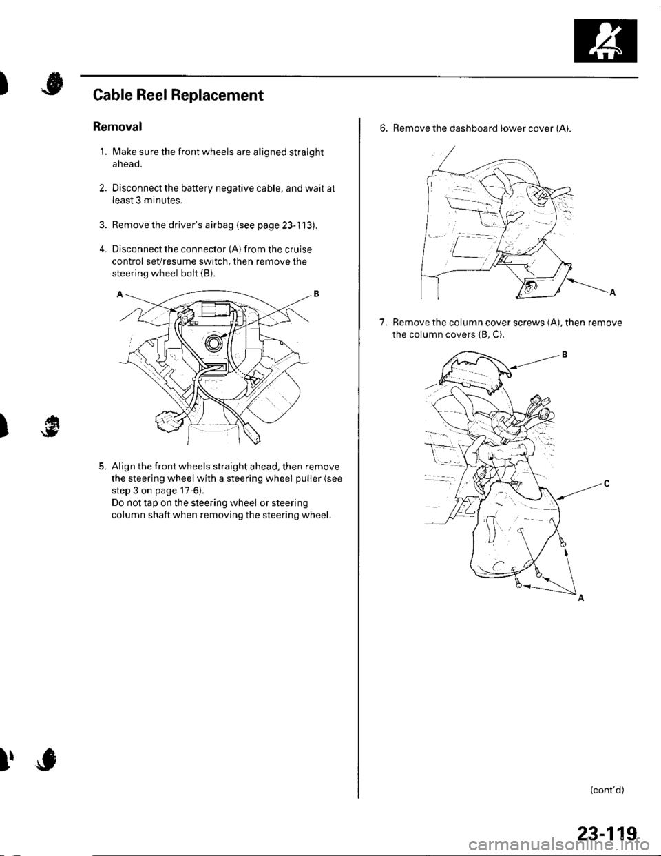
Disconnect the connector (Al from the cruise
control sevresume switch, then remove the
steering wheel bolt (B).
Align the front wheels straight ahead, then remove
the steering wheel with a steering wheel puller (see
step 3 on page '17-6).
Do not tap on the steering wheel or steering
column shaftwhen removing the steering wheel.
)
5.
I,
6. Remove the dashboard lower cover (Ai.
Remove the column cover screws (A), then remove
the column covers (8, C).
7.
(cont'd)
23-119
Page 1127 of 1139
sRs
Cable Reel Replacement (cont'd)
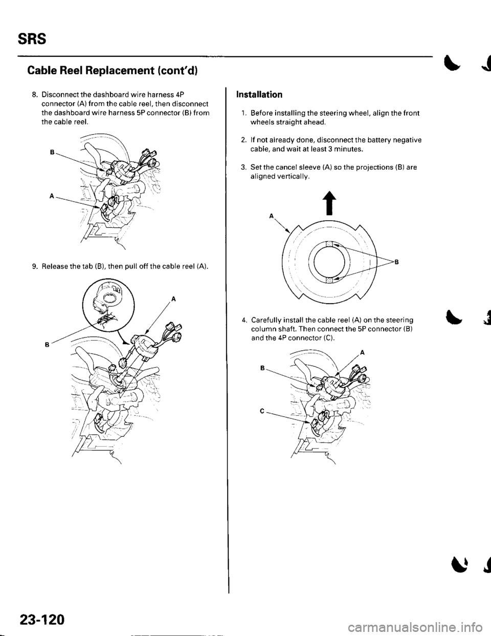
Disconnect the dashboard wire harness 4P
connector (A)from the cable reel, then disconnect
the dashboard wire harness 5P connector {B} from
the cable reel.
9. Release the tab (B), then pull offthecable reel (A).
23-120
J
Installation
1. Before installing the steering wheel. align the front
wheels straight ahead.
2. lf not already done, disconnect the battery negative
cable, and wait at least 3 minutes.
3. Setthe cancel sleeve (A) so the projections (B) are
aligned vertically.
Carefully install the cable reel (A) on the steering
column shaft. Then connect lhe 5P connector {B)
and the 4P connector (C).
I4.
J
Page 1129 of 1139
sRs
SRS Unit Replacement
Removal
'1. Disconnect the battery negative cable, and wait at
least 3 minutes before beginning work.
2. Disconnect the driver's and front passenger's
airbag connectors (see page 23-21).
3. Disconnectthe side airbag connectors (see page
23-211.
4.Disconnect both seat belt tensioner connectors (see
page 23-22) and both seat belt buckle tensioner
connectors {see page 23-221.
Remove the dashboard center lower cover (see
step 2 on page 20-57).
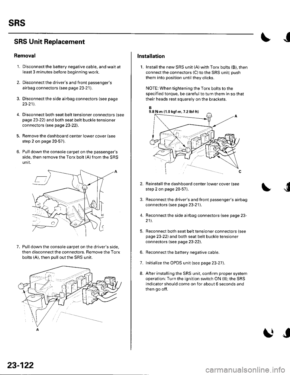
Pull down the console carpet on the passenger's
side, then remove the Torx bolt (A)from the SRS
unit.
7. Pull down the console carpet on the driver's side,
then disconnect the connectors. Remove the Torx
bolts (A), then pull out the SRS unit.
23-122
lnstallation
1, Installthe new SRS unit (A)with Torx bolts (B), then
connect the connectors {C) to the SRS uniu push
them into position until they clicks.
NOTE: When tightening the Torx bolts to the
specified torque, be careful to turn them in so that
their heads rest squarely on the brackets.
Reinstall the dashboard center lower cover (see
step 2 on page 20-57).
Reconnect the driver's and front passenger's airbag
connectors (see page 23-21]'.
Reconnect the side airbag connectors (see page 23-
211.
Reconnect both seat belt tensioner connectors (see
page 23-221 and both seat belt buckle tensioner
connectors (see page 23-22).
Reconnect the battery negative cable.
Initialize the OPDS unit (see page 23'27).
After installing the SRS unit, confirm proper system
operation: Turn the ignition switch ON (ll); the SRS
indicator should come on for about 6 seconds and
then go off.
4.
6.
8.
7.
9.8 N.m (1.0 kgf m, 7.2 lbf ft)
Page 1134 of 1139
Service Manual Index
(cont'dl
Brake System Indicator CircuitCircuit DiagramConventional Brake Components..... 19-9TroubleshootingABS/TCS Components .... ....... ...... 19-55
Bulb, GeugeRep|acemenl................ .. ............2263
Bulb, HeadlightReplacement ......................................... 22-A1
Bumper, FrontRemoval/1nsra11ation ............................ 20 85
Bumper, RearRemoval/lnstallation... ... . .....20.86
Combination Light SwilchTesVReplacement ..............................22 80
Connecting Rod BearingsRep|acement...................... .......-....7-8
Connecting Rod Boltsf nspection ....................-.-.-.-.................... 7 -24
Connecting RodsInspection ........,,.,.,...,.,.,.,.,,,,.,,,.,.,.,.,.,.,.,.. 7 5
Connectors(See first page of this Index)
Conventional Brake Component3Component Location Index ................... 19'3Troub1eshootin9 ..................................... 19-4
Cylinder Head AssemblyComponent Location Index ..................... 6-3Inspection ................................................. 6 6Removal ..........&�23Insta11alion .............................................. 6 39
Cylinder Head Cover8emova1 ..............-.-................................. 6-22Installation ..............................................6-41
Cylinder Head, BareInspecton..,.....,.
D
c
Cable ReelReplacement....................................... 23-1 19
CamshaftInspection .......................-...-................... 6-29
Cargo Area LightTesVRep1acement ................................ 22-97
CarpetReplacement.....-...-..... ... ......-.20-55
Ceiling Light-estrReplacement ................................ 22.96
Charging SystemComponent Location Index................... 4-20Circuit Diagram ...................................... 4-21
19-8
CoolantInspection .................. ..... .. 106Replacement................. ... . .. 10 6
Coolant Temperature Gat|geTroub1eshootin9................................... 22 64
Cooling SyslemComponent Location Index................... 10-2
Countershaft BearingsReplacement............... ..................... 13-42
Cowl CoverReplacement............... .. ..... ....20-95
CrankshaftRemoval .................................................. 7 -12
Repair ..................
Inspec(on,,,,,........1 14
Dampers. FrontReplacement................ ..................... 18 20
Oampers, RearRep1acement......................................... 18-34
Dash VentsBemoval/lnstallation .-.......................... 20-64
DashboardBemoval/1nsta11ation ............................ 20-66
Oashboard Center PanelRemoval/1nstaf 1ation ............................ 20 62
Dashboard Lower CoverRemoval/lnstallation ...................... 20-59, 63
Dashboard Under CoverRemoval/lnstallation ............................ 20 60
Diff erential Carrier Bearings, M/TRep1acement,,......,...,...,.,.,,,.,.,,,........,.,. 13-54
Ditferential Oil Seals, M/T8ep1acement......................................... 13-55
Differential Pinion Gears, M/TInspection .,....-,.,,,.,..,.-,.,.........,.,.,,, 13 53
OLC CircuitTroubleshooting ................................ 1 1-109
Door GlassRep1acement.,.,,,,,,,,,,,.,,,,,,,,,,.,.,.,.,.,,,,,,.,, 20-9Adjustment. .. .....................20-11
Door Glass WeathelstripsReplacement .............-.. . . . ..........-......20 10
Door LatchesReplacement ..........-.-.............................. 20-7
Door Lock ActuatorsTest ...................................................... 22-154
Door Lock Knob SwitchesTest -......... . . . - . . . . . . . . ......22-160
Door Lock SwitchesTest ........... ............................ ............. 22-160
Door Outer HandlesRep1acemen1 ........................................... 20-6
3
Child Seat Tether AnchorRemoval/lnstaf lat;on .. ........................ 23 11
CKP (Crankshaft Position) SonsorReplacement....................................... 1 1-116
ClutchComponentLocation 1ndex................... 12-3Rep1acemen1........................................... 12-9
Clutch InteYlock SwitchTest.....-........-...-............. ...---.-.......4-6
Clutch Master CylinderReplacement........................................... 12 5
clutch PedalAdjustment ............................................. 12 4
Clutch Pedal Position SwitchTest.,.,,,,,.,,,.,.,,,,,,.,.,,,,,,,,,.,,,,,.. ......445
lnstallation.................. . ..... .....1-24
Crankshalt Main BearingsReplacement........-.-.................................. 7-6
CrankshaftOil Seal,Transmission End1nstanation .............................................. 7 28
Crankshafl PulleyRemoval/lnstallation -..................-.......... 6-1 1
Cruise Control Actuator
Troubleshooting
Clutch Slave CylindorBeplacemeit...
...................... 4-43
.......4-22
Test
12-1
RepIacement........................................... 4-44
Cruise Control Actuator CableAdjustment ............................................. 4 45
Cruise Control Main SwitchTesVRep1acement .................................. 4 42
Cruise Control Set/Resume/Cancel SwitchTesVRep1acement .................................. 4 42
Cruise Control SystomComponent Localion Inde\................... 4-36Circuit Diagram ....-................................. 4 37
Cruise Control UnitInputTest.............................. .. ...4,40CMP {Camshaft Positionl Senso]Replacement....-...-.............................. 1 1-128
CMP (TDC) SensorsReplacement............-.......................... 1 1 1 14