dashboard HONDA CIVIC 2002 7.G Repair Manual
[x] Cancel search | Manufacturer: HONDA, Model Year: 2002, Model line: CIVIC, Model: HONDA CIVIC 2002 7.GPages: 1139, PDF Size: 28.19 MB
Page 997 of 1139
lmmobilizer System
Troubleshooting (cont'dl
8. Check for voltage betvveen the immobilizer control
unit-receiver 7P connector No. 6 terminal and No. 1
rermlnat.
ls thete battery voltage?
YES Go to step 12.
NO Check for these problems,
. Open on the BRNI/EL wire.l. Faulty ECM.I
9. Remove the driver's dashboard lower cover (see
page 20-59).
10. Remove the steering column lower cover (see page
17-9).
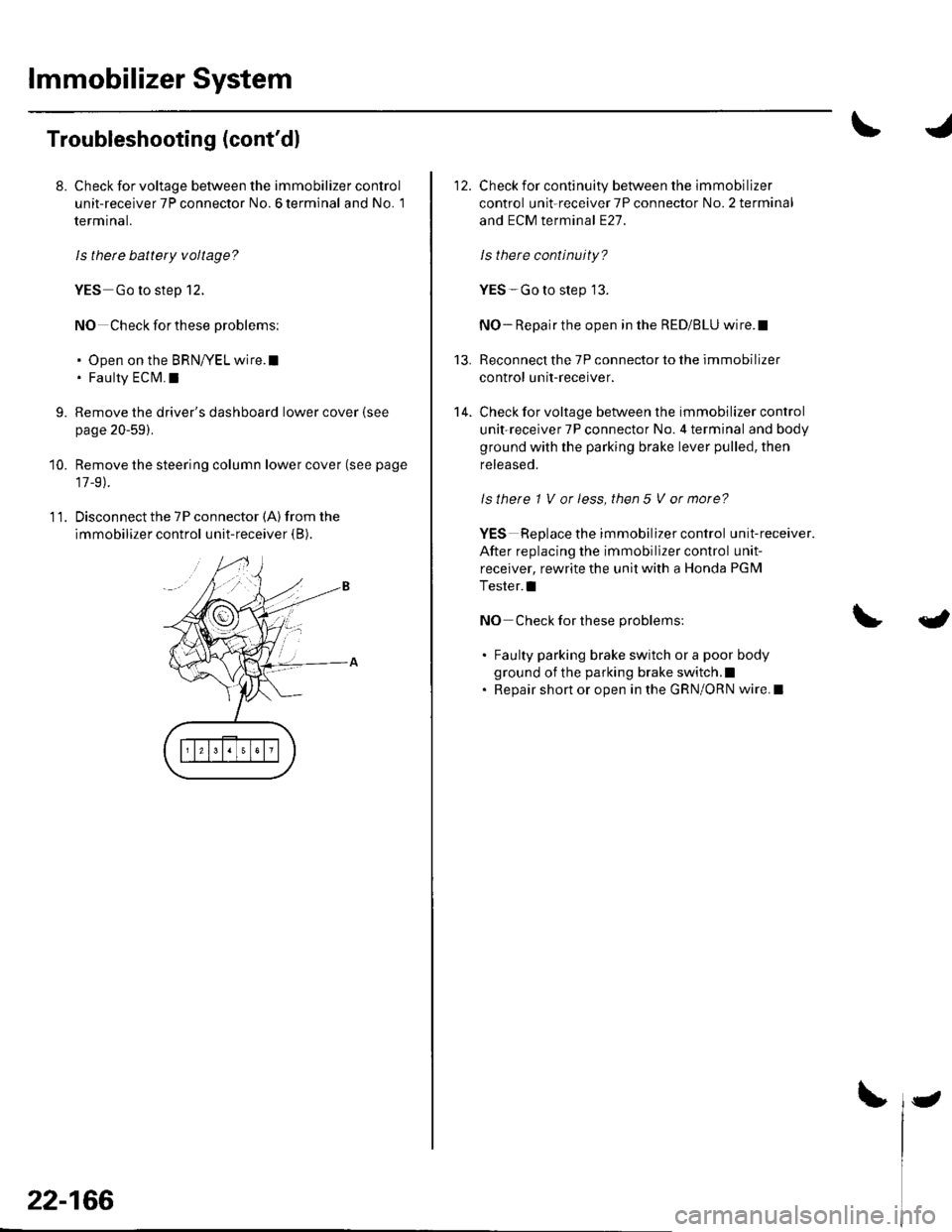
11. Disconnect the 7P connector (A) from the
immobilizer control unit-receiver (B).
22-166
-
Check for continuity between the immobilizer
control unit-receiver 7P connector No. 2 terminal
and ECM terminal E27.
ls there continuity?
YES-Go to step 13.
NO- Repair the open in the RED/BLU wire.I
Reconnect the 7P connector to the immobilizer
control unit-receiver.
Check for voltage between the immobilizer control
unit-receiver 7P connector No. 4 terminal and body
ground with the parking brake lever pulled, then
released.
ls there 1 V or less, then 5 V or more?
YES Replace the immobilizer control unit-receiver.
After replacing the immobillzer control unit-
receiver, rewrite the unit with a Honda PGM
Tester.l
NO Check for these problems:
. Faulty parking brake switch or a poor body
ground of the parking brake switch.l. Repair short or open in the GRN/ORN wire. I
13.
14.
{
Page 998 of 1139
t
2.
3.
lmmobilizer Control Unit-Receiver Replacement
'LRemove the driver's dashboard lower cover (see
page 20-59).
Remove the steering column covers (see page 17-
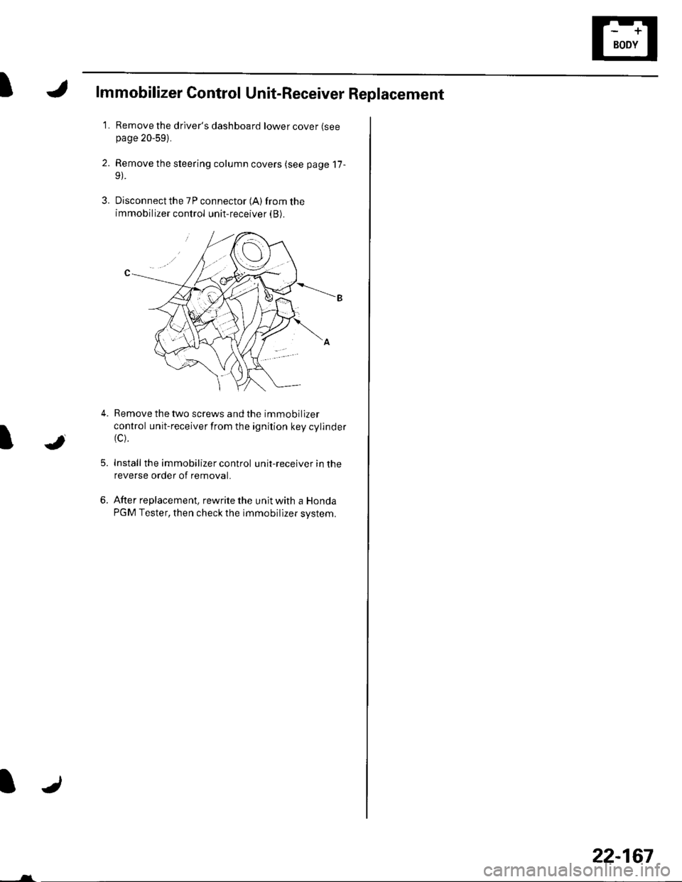
Disconnect the 7P connector (A) from the
immobilizer control unit-receiver (B).
5.
Remove the two screws and the immobilizer
control unit-receiver from the ignition key cylinder(c).
Install the immobilizer control unit-receiver in the
reverse order of removal.
After replacement, rewrite the unit with a Honda
PGM Tester, then check the immobilizer system.
JI
6.
-___-l-
22-167
Page 1003 of 1139
Multiplex Control System
Troubleshooting
Mode 1 Tset
1. Remove the driver's dashboard lower cover {see
page 20-59).
2. Check the No. 9 ( 10A) fuse in the under-hood fuse/
relay box and the No. 10 (7.5A) fuse in the under-
dash fuse/relay box.
Are the fuses OK?
YES-Go to step 2.
NO-Find and repairthe cause ofthe blown fuse.!
3. Turn the ignition switch ON (ll).lf the driver's
seatbelt is unbuckled the seat belt reminder will
chime 6 times.
4. Set the ceiling light to the center position and close
allthe doors.
5. Connect the specialtoolto the multiplex inspection
conneclor.
6. After about 5 seconds the spotlight and ceiling light
should come on for 2 seconds, go out, then blink on
for 0.2 second to show the system is now in mode
1.
Did the spotlight and ceiling light indicate mode
1?
YES-Go to step 8.
NO Go to step 7.
22-172
-
7. Check for continuity between terminal 4ofthe
under-dash fuse/relay box connector J and body
ground.
ls there continuity?
YES Replace the under-dash fuse/relay box.l
NO - Repair the open in the wire.lf the wire is ok,
repair G301.1
8. lf ther are any DTCS present, the spotlight and
ceiling light will blink to indicate the DTC(S). lf more
than one DTC is present, the DTCS will be displayed
in ascending order, lf there are no DTCS the
spotlight and ceiling light will not blink again after
the mode 1 indication.
Are there any DTCg?
YES Go to step 9.
NO Go to the Mode 2 test.
9. Troubleshoot the DTC(S) in the order indicated
using the following charts.
lf a faulty control unit is suspected, substitute it
with a known food part and recheck for DTCS,
. lf the DTC(s) isstill present. go to the next step
listed for the DTC.. lf the DTC(S) is no longer present replace the
original part.
Page 1006 of 1139
IMultiplex Control Unit Input Test
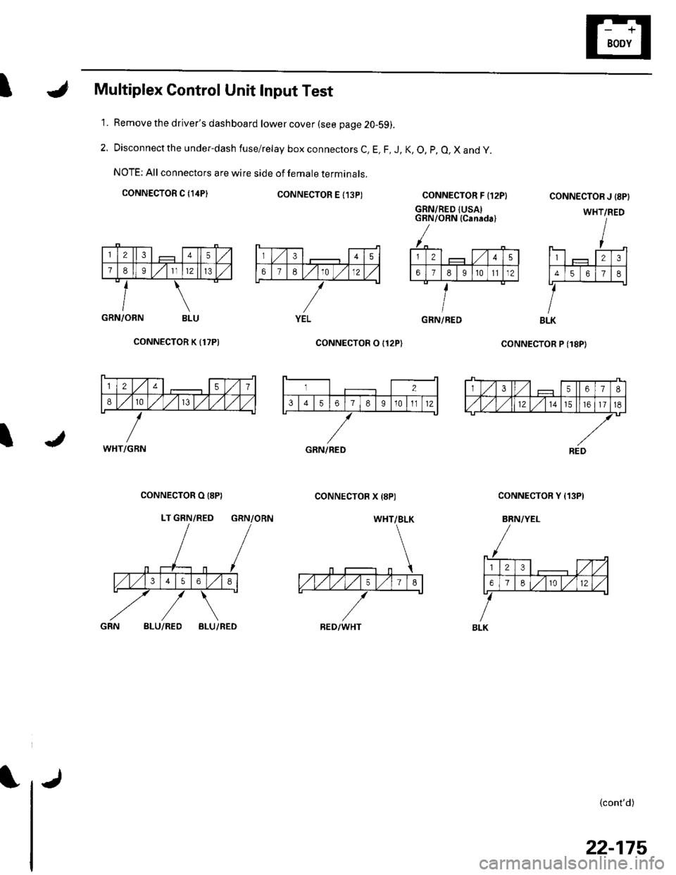
Remove the driver's dashboard lower cover (see page 20-59).
Disconnect the under-dash fuse/relay box connectors C, E, F, J, K, O, p, O, X and y.
NOTE: All connectors are wire side of female terminals.
CONNECTOR C {14P}CONNECTOR E I13P)
1.
2.
CONNECTOR F {12P}
GRN/RED {USAIGRN/ORN (Canada)
coNNECTOR P (18P)
CONNECTOR J {8PI
WHT/RED
123
4561
BLK
{cont'd)
GRN/ORN BLU
CONNECTOR K {17P)
I
CONNECTOR O I12P)
CONNECTOR X {8P)CONNECTOR O (8P}
LT GRN/RED GRN/ORN
CONNECTOR Y {13P)
BRN/YEL
BLU/REDBLU/RED
345
67E10 )./12
YELGRN/RED
12457
810/V,/ l,/
WHT/GBN
3567I
,/1,/l,/121517
REDGRN/RED
WHT/BLK
RED/WHT
23,/1,/
618r012
BLK
22-175
Page 1027 of 1139
sRs
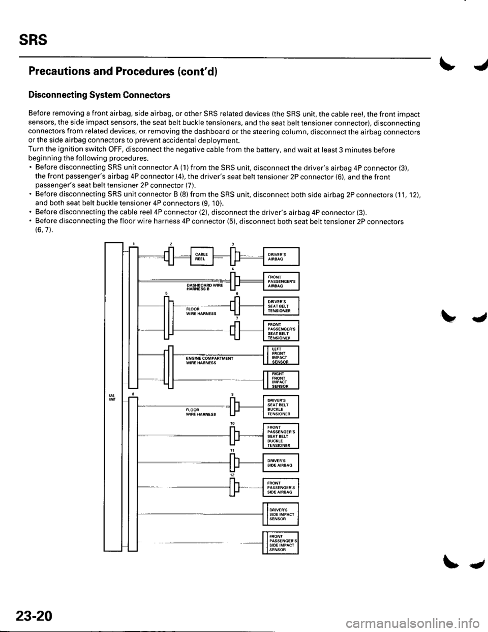
Precautions and Procedures (cont'dl
Disconnecting System Connectors
Before removing a front airbag. side airbag, or other SRS related devices {the SRS unit, the cable reel, the front impact
sensors, the side impact sensors, the seat belt buckle tensioners, and the seat belt tensioner connector), disconnectingconnectors from related devices, or removing the dashboard or the steering column, disconnect the airbag connectorsor the side airbag connectors to prevent accidental deploVment.
Turn the ignition switch OFF, disconnect the negative cable from the battery, and wait at least 3 minutes before
beginning the following procedures.'BeforedisconnectingSRSunitconnectorA(1)fromtheSRSunit,disconnectthedriver'sairbag4Pconnector(3).
the front passenger's airbag 4P connector (4), the driver's seat belt tensioner 2P connector (6), and the frontpassenger's seat belt tensioner 2P connector (7).
. Before disconnecting SRS unit connector B (8) from the SRS unit, disconnect both side airbag 2P connectors (11. '12),
and both seat belt buckle tensioner 4P connectors (9, 10).. Before disconnecting the cable reel 4P connector (2), disconnect the driver's airbag 4P connector (3).'Beforedisconnectingthefloorwireharness4Pconnector(5),disconnectbothseatbelttensioner2Pconnectors
(6.7).
23-20
\.
Page 1028 of 1139
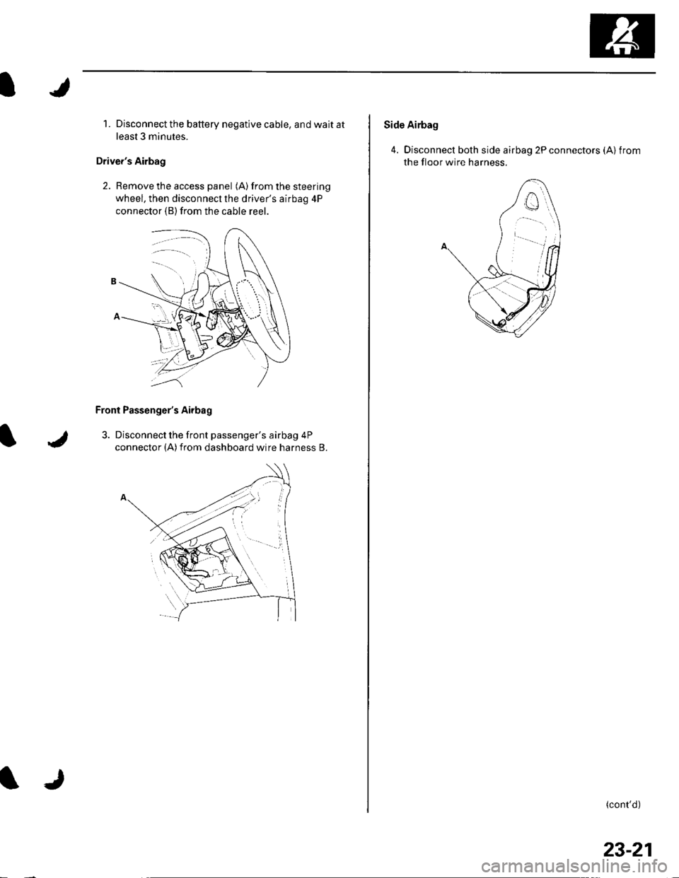
1. Disconnect the battery negative cable, and wait at
least 3 minutes.
Driver's Airbag
2. Remove the access panel (A) from the steering
wheel, then disconnecl the driver's airbag 4P
connector (B)from the cable reer.
Front Passenger's Airbag
3. Disconnect the front passenger's airbag 4P
connector (A)from dashboard wire harness B.
Side Airbag
4. Disconnect both side airbag 2P connectors (Alfrom
the floor wire harness.
(cont'd)
23-21
Page 1043 of 1139
sRs
J
a
DTC Troubleshooting
DTC 1-1: Open in Driver's Airbag Inflator
DTC 1-2: Increased Resistance in Driver's
Airbag Inflator
Special Tools Required. SRS inflator simulator 07SAZ-TB4011A. SRS simulator lead F 07XAZ-S230100
1. Erase the DTC memory (see page 23-26).
2. Turn the ignition switch ON {ll), and check that the
SRS indicator comes on for aboul 6 seconds and
then goes off.
Does the SBS indicator stay on?
YES-Go to step 3.
NO Intermittent failure, system is OK at this time.
Go to Troubleshooting Intermittent Failures (see
page 23-26).
3. Turn the ignition switch OFF. Disconnect the
battery negative cable, and wait for 3 minutes.
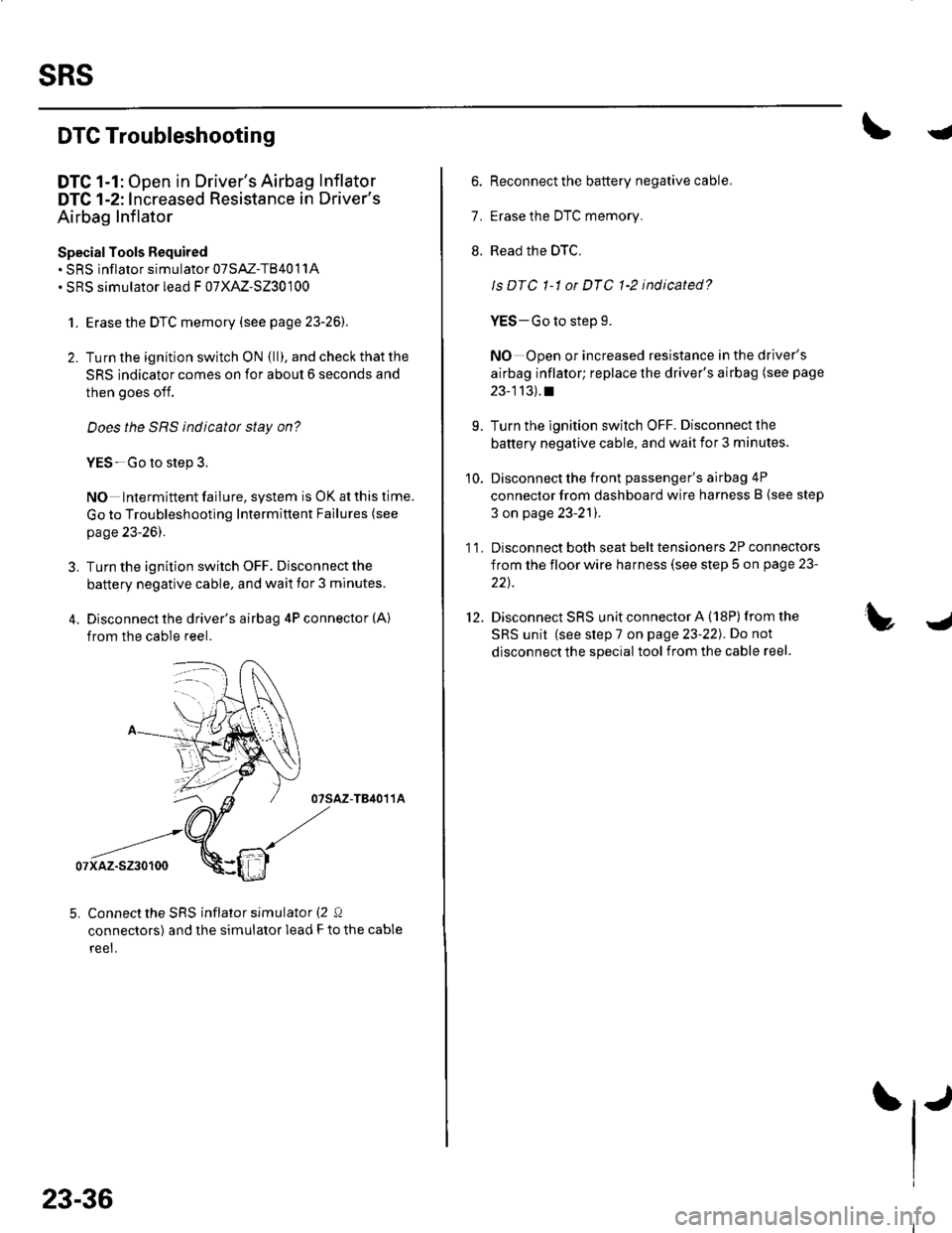
4. Disconnect the driver's airbag 4P connector (A)
from the cable reel.
07sAz-TB4011A
07xaz-s230100
5. Connect the SRS inflator simulator (2 Q
connectors) and the simulator lead F to the cable
reet.
23-36
6. Reconnect the battery negative cable.
7. Erase the DTC memory.
8. Read the DTC,
ls DTC 1-1 or DTC 1-2 indicated?
YES-Go to step 9.
NO Open or increased resistance in the driver's
airbag inflator; replace the driver's airbag (see page
23-113).t
9. Turn the ignition switch OFF. Disconnect the
battery negative cable, and wait ior 3 minutes.
10. Disconnect the front passenger's airbag 4P
connector from dashboard wire harness B (see step
3 on page 23-21).
1 1. Disconnect both seat belt tensioners 2P connectors
from the floor wire harness (see step 5 on page 23-
22t.
12. Disconnect SRS unit connector A (18P)from the
SRS unit (see step 7 on page 23-22). Do not
disconnect the special tool from the cable reel.
Page 1044 of 1139
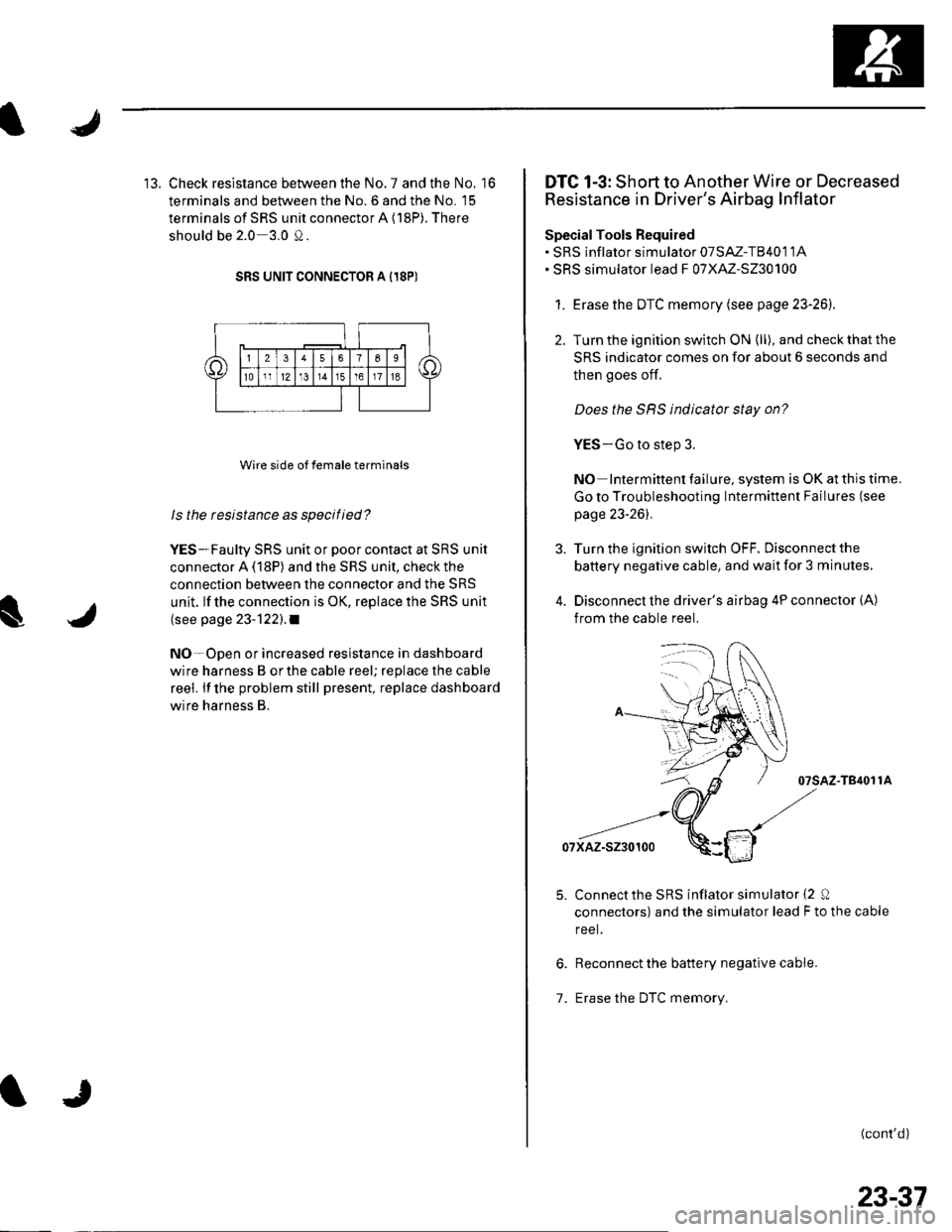
13. Check resistance between the No. 7 and the No. '16
terminals and between the No. 6 and the No. 15
terminals of SRS unit connector A (18P). There
should be 2.0 3.0 0.
SRS UNIT CONNECTOR A I18P)
Wire side of female terminals
ls the resistance as specilied?
YES-Faulty SRS unit or poor contact at SRS unit
connector A (18P) and the SRS unit, check the
connection between the connector and the SRS
unit. lf the connection is OK, replace the SRS unit
(see page 23-122).1
NO-Open or increased resistance in dashboard
wire harness B orthe cable reel; replace the cable
reel. lf the problem still present, replace dashboard
wire harness B.
DTC 1-3: Short to Another Wire or Decreased
Resistance in Driver's Airbag Inflator
SpecialTools Required. SRS inflator simulator 07SAZ-T8401 1A. SRS simulator lead F 07XAZ-S230100
1. Erasethe DTC memory (see page 23-26).
2. Turn the ignition switch ON (ll), and check that the
SRS indicator comes on for about 6 seconds and
then goes of{.
Does the SRS indicator stay on?
YES-Go to step 3.
NO Intermittent failure, system is OK at this time.
Go to Troubleshooting Intermittent Failures (see
page 23-261.
Turn the ignition switch OFF. Disconnect the
battery negative cable, and wait for 3 minutes,
Disconnect the driver's airbag 4P connector (A)
from the cable reel.
07sAz-T84011A
07xAz-s230100
Connectthe SRS inflator simulator {2 0
connectors) and the simulator lead F to the cable
reel.
Reconnect the battery negative cable.
Erase the DTC memory.1.
(cont'd)
23-37
Page 1045 of 1139
sRs
DTC Troubleshooting {cont'd)
8. Read the DTC.
Is DTC 1-3 indicated?
YES Go to step 9.
NO Short in the driver's airbag; replace the
driver's airbag (see page 23-'l 13).1
9. Turn the ignition switch OFF. Disconnect the
battery negative cable, and wait for 3 minutes.
10. Disconnect the front passenger's airbag 4P
connector from dashboard wire harness B (see step
3 on page 23-21).
1 '1. Disconnect both seat belt tensioner 2P connectors
from the floor wire harness (see step 5 on page 23-
22t.
12. Disconnect SRS unit connectorA (18P)from the
SRS unit (see step 7 on page 23-221.
13. Disconnectthe special tool from the cable reel.
23-38
IJ
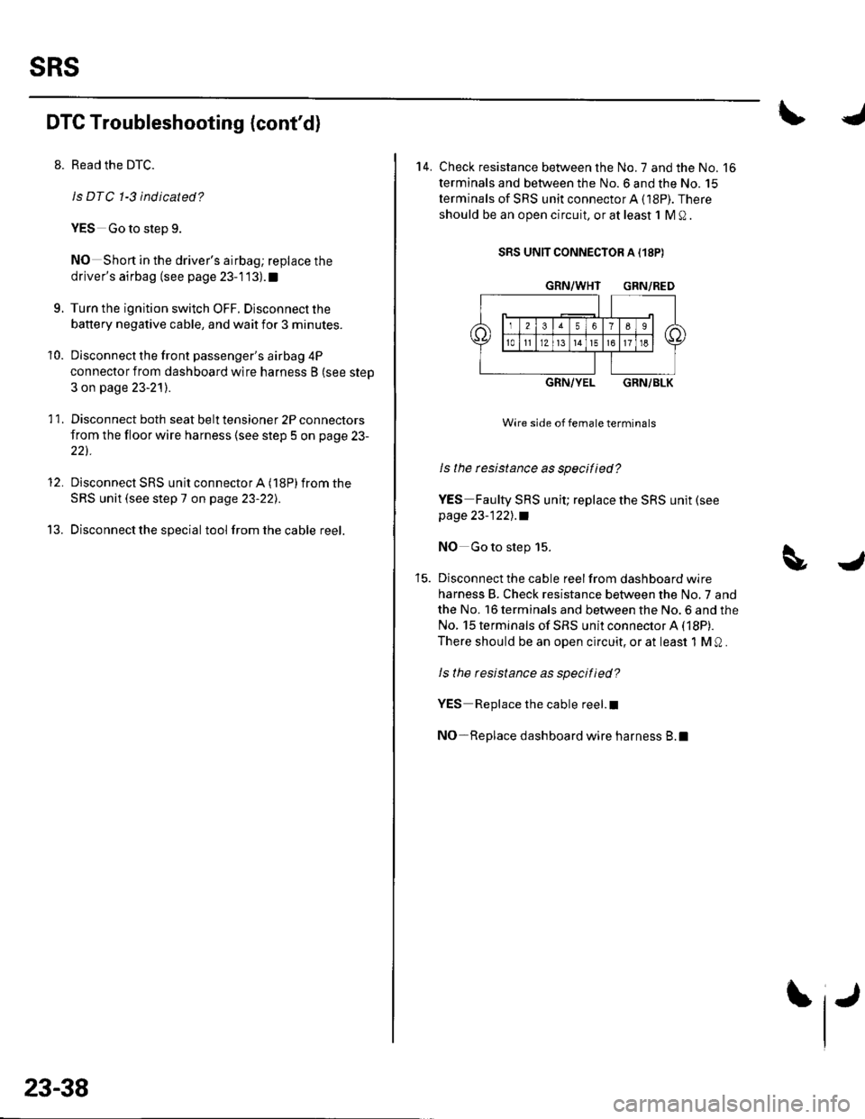
14. Check resistance between the No. 7 and the No. 16
terminals and between the No.6 and the No. 15
terminals of SRS unit connectorA (18P). There
should be an open circuit, or at least 1 M Q .
SRS UNIT CONNECTOR A {18P)
GRN/WHT GRN/RED
GRN/YELGRN/BLK
Wire side of female terminals
ls the rcsistance as specified?
YES Faulty SRS unit; replace the SRS unit (see
page 23-122],.a
NO Go to step 15.
Disconnect the cable reel from dashboard wire
harness B. Check resistance between the No,7 and
the No. 16 terminals and between the No. 6 and the
No. 15 terminals of SRS unit connector A (18P).
There should be an open circuit, or at least 1 M Q .
ls the resistance as specified?
YES Replace the cable reel.I
NO-Replace dashboard wire harness B.l
Page 1046 of 1139
s
DTC 1-4: Short to Power in Driver's Airbag
Inflator
SpecialTools Bequired. sRS inflator simulator 07SAZ-T84011A. SRS simulator lead F 07XAZ-S230100
1. Erase the DTC memory (see page 23-26).
2. Turn the ignition switch ON (ll), and check that the
SRS indicator comes on for about 6 seconds and
then goes off.
Does the SRS indicator stay on?
YES Go to step 3.
NO Intermittent failure, system is OK at this time.
Go to Troubleshooting Intermittent Failures (see
page 23-26).
3. Turn the ignition switch OFF. Disconnect the
battery negative cable, and wait for 3 minutes.
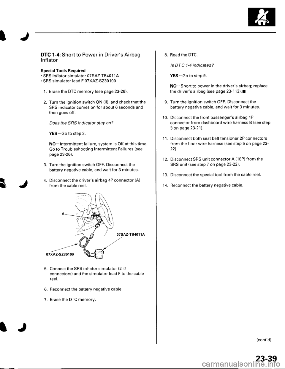
4. Disconnect the driver's airbag 4P connector (A)
from the cable reel.
07sAz-T84011A
Connect the SRS inflator simulator (2 0
connectors) and the simulator lead F to the cable
reel.
Reconnect the battery negative cable.
Erase the DTC memory.
6.
1.
9.
10.
't 4.
11.
12.
Read the DTC.
ls DTC 1-4 indicated?
YES-Go to step 9.
NO-Short to power in the driver's airbag; replace
the driver's airbag (see page 23-1 13).1
Turn the ignition switch OFF. Disconnect the
battery negative cable, and wait for 3 minutes.
Disconnect the front passenger's airbag 4P
connector from dashboard wire harness B (see step
3 on page 23'21).
Disconnect both seat belt tensioner 2P connectors
from the floor wire harness (see step 5 on page 23-
221.
Disconnect SRS unit connector A (18P)from the
SRS unit (see step 7 on page 23-22).
Disconnect the special tool from the cable reel.
Reconnect the battery negative cable.
(cont'd)
23-39