EPS HONDA CIVIC 2002 7.G User Guide
[x] Cancel search | Manufacturer: HONDA, Model Year: 2002, Model line: CIVIC, Model: HONDA CIVIC 2002 7.GPages: 1139, PDF Size: 28.19 MB
Page 229 of 1139
![HONDA CIVIC 2002 7.G User Guide Fuel and Emissions Systems
System Descriptions (contdl
ECM lnputs and Outputs at Connector E (31P}
L
u
1iMoFPR
2sr-{]zs3LG34SG3
6$1025HTC
1M RLY
8AFSHTCR
I
14FTP15ELD
16EPSLD
18ACC20Z/VBS21VSV
22BKSW HONDA CIVIC 2002 7.G User Guide Fuel and Emissions Systems
System Descriptions (contdl
ECM lnputs and Outputs at Connector E (31P}
L
u
1iMoFPR
2sr-{]zs3LG34SG3
6$1025HTC
1M RLY
8AFSHTCR
I
14FTP15ELD
16EPSLD
18ACC20Z/VBS21VSV
22BKSW](/img/13/5744/w960_5744-228.png)
Fuel and Emissions Systems
System Descriptions (cont'dl
ECM lnputs and Outputs at Connector E (31P}
L
u
1iMoFPR
2sr-{]zs3LG34SG3
6$1025HTC
1M RLY
8AFSHTCR
I
14FTP15ELD
16EPSLD
18ACC20Z/VBS21VSV
22BKSW23K-LINE24SEFMJ26NEP
21rMoCD
29scs30WEN31MIL
Wire side of female terminals
NOTE: Standard battery voltage is '12 V.
TerminalnumberWire colorferminal nameDescription Signal
GRNI/ELIMO FPR (IMMOBILIZERFLJEL PUMP RELAYIDrives PGM Fl main relay 20Vfor2 seconds after turning ignition switch ON{ll). then batterv voltaoe2WHT/REDSHO2S (SECONDARYHEATED OXYGEN SENSOR(SECONDARY HO2S),SENSOR 2r
Detects secondary HO2S{sensor 2) signalWith throttle Jully opened from idle with fullywarmed up engine: above 0.6VWith throttle quickly closed: below 0.4 V
3BRN/YELLG3 (LOGIC GROUND)cround forthe ECM/PCMcontrolcircuitLess than 1.0 V at all times
4PNKSG3 {SENSOR GBOUND)Sensor oroundLess than 1.0 V at all times5YEUELUVCC3 {SENSOR VOLTAGE)Provides sensor voltageWith ignition switch ON (ll): about 5 VWith ionition switch OFF: about 0 V6BLKATr'HTSO25HTC (SECONDARYHEATED OXYGEN SENSOR(SECONDARY H02S)HEATER CONTROL)
Drives secondary HO2SheaterWith ignition switch ON (ll): baftery voltageWilh fullv warmed up engine running: dul,controlled
1REDA/ELMRLY (PGM.FI MAINRELAY}Drives PGM-Flmain relay 1Power source forthe DTCWith ignition switch ON (ll): about 0 VWith ignition switch OFF: battery voltage
IORNAFSHTCR {AIR FUEL BATIO(Iy'F)SENSOR HEATERCONTROL RELAY)
Drives air fuel ratio sensorheater relayWith ignition swirch ON {ll): 0 V
IYEUBLKIGl (IGNITION SIGNAL)Detecrs ignition signalWith ignition switch ON (ll): battery voltageWith iqnition switch OFF: about 0 V't4LT GRNFIP lFUEL TANKPRESSURE (FTP) SENSOR)Detects FTP sensor signalWith ignition switch ON (ll) and fuel fill cap open:about 2.5 VGRN/REDELD (ELECTRICAL LOADDETECTOF)Detects ELD signalWith ignition swjtch ON itt):aOoutO.t V l-gV(deDendino on electrical load)LT GRN/8LKEPSLD (ELECIRICALPOWEB STEEBING LOADDETECT)
Detects Power steering loadsrgnalAt idle with steering wheel in straight aheadposition: about 0 VAt idle with steering wheelatfull lock: momentary
'18REDACC (Ay'C CLUTCH RELAY)Drives P,/C clutch relayWith compressor ON: about 0 VWith comoressor OFF: batterv voltaoe
11-22
\-
Page 230 of 1139
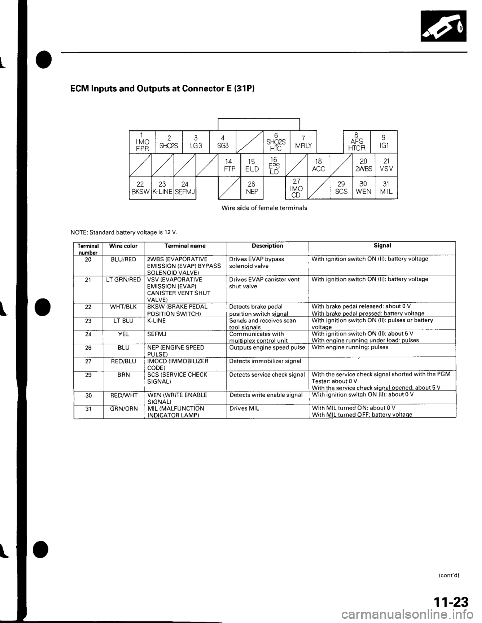
ECM Inputs and Outputs at Connector E (31P)
ltMoFPR
2$.c2s
i6SFIO2SHTC
1
IV RLY
IAFSHTCR
9tGl
14FTP15ELD
16EPSLD
t8202,4/BS21VSV
22BKSW23K LINE24SEFMJ26NEP
21lvoCD
29scs30WEN31MIL
Wire side of female terminals
NOTE: Standard battery voltage is 12 V.
TerminalWire colorTerminalnameDescriptionSignal
20BLU/RED2WBS (EVAPORATIVEEMISSION (EVAP)BYPASSSOLENOID VALVE)
Drives EVAP bypass With ignition switch ON (ll): baftery voltagesolenoid valve
21LT GRN/REDVSV (EVAPORATIVE
EI\4ISSION iEVAP)CANISTEB VENT SHUTVALVE)
Drives EVAP canister ventshut valveWith ignilion switch ON (ll): battery voltage
22WHT/BLKBKSW lBRAKE PEDALPOSITION SWITCH)Detects brake pedaloosition switch sionalWith brake pedal released: about 0 VWith hrake nedal nresse.l: batterv voltaoe23LT BLUK-LIN ESends and receives scanWith ignition switch ON (li)r pulses or battery
YELSEFMJCommunicates withmrltinleY eontrol unitWith ignition switch ON (ll): about 5 VWith enoine runnino under load: DUlses26BLUNEP (ENGINE SPEEDPULSE)Outputs engine speed pulseWith engine running: pulses
21RED/BLU \40CD fl\4MOBTLTZERCODE)Detects imrnobilizer signal
29BRNSCS (SERVICE CHECKSIGNAL)Oetects service check signalWith the service check signal shorted with the PGMTester: about 0 VWiih rhe service check sional ooened: about 5 V
30RED,A/VHTWEN (WRITE ENABLESIGNALiDetects write enable signal With ignition switch ON (ll): about 0 V
GRN/ORNMIL (MALFUNCTION
INDICATOR LAMP)Drives N4lLWith MIL turned ON: about 0 VWith MIL turned OFF: batterv voltaqe
(cont'd)
11-23
Page 239 of 1139
Fuel and Emissions Systems
(
{
System Descriptions (cont'd)
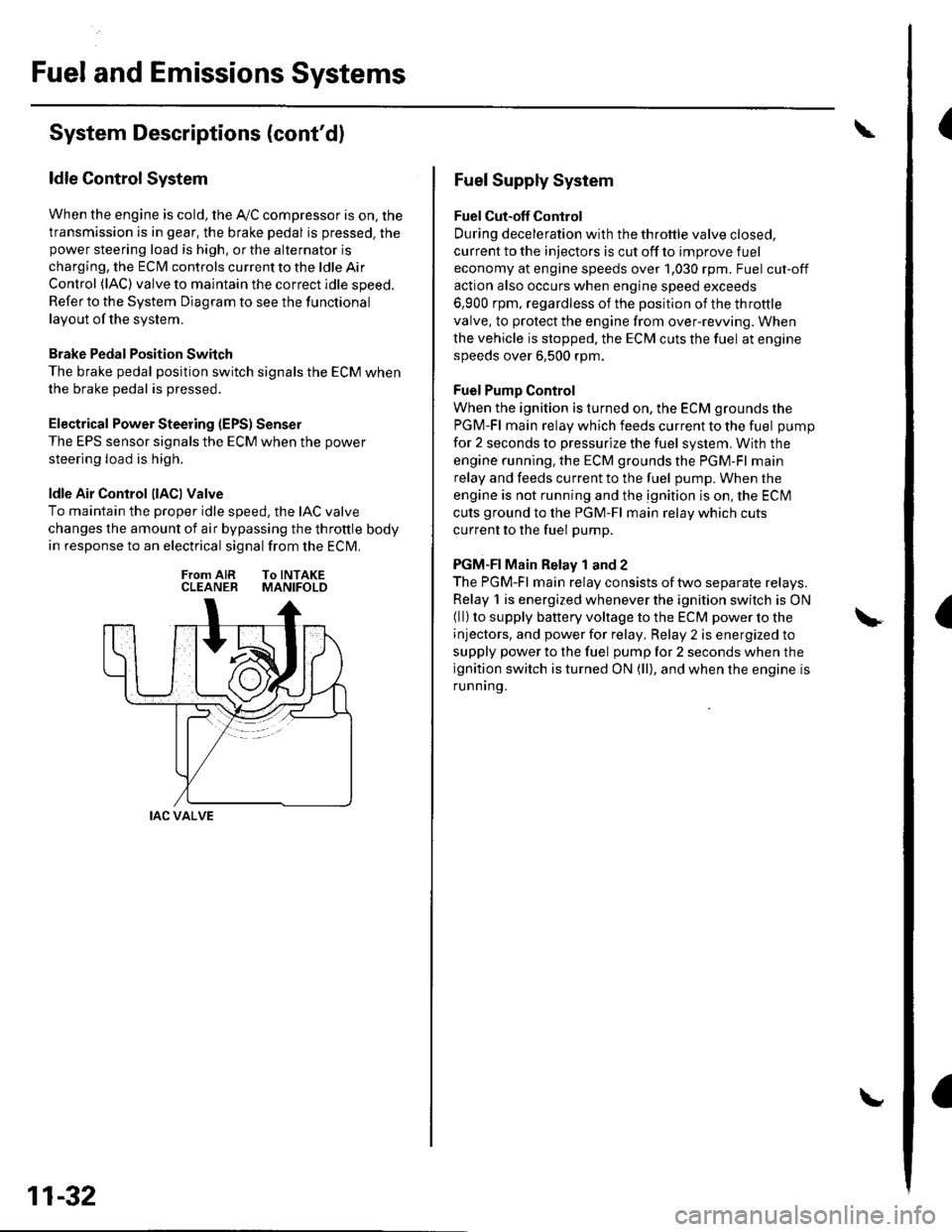
ldle Control System
When the engine is cold, the Ay'C compressor is on, the
transmission is in gear, the brake pedal is pressed. thepower steering load is high, or the alternator is
charging, the ECIM controls current to the ldle Air
Control (lAC) valve to maintain the correct idle speed.
Refer to the System Diagram to see the functional
layout of the system.
Brake Pedal Position Switch
The brake pedal position switch signals the ECM when
the brake pedal is oressed.
Electrical Power Steering (EPS) Senser
The EPS sensor signals the ECM when the power
steering load is high.
ldle Air Control llACl Valve
To maintain the proper idle speed, the IAC valve
changes the amount of air bypassing the throttle body
in response to an electrical signal from the ECM.
From AIR To INTAKECLEANER MANIFOLD
IAC VALVE
11-32
Fuel Supply System
Fuel Cut-off Control
During deceleration with the throttle valve closed,
current to the injectors is cut off to improve fuel
economy at engine speeds over 1,030 rpm. Fuel cut-off
action also occurs when engine speed exceeds
6,900 rpm, regardless of the position of the throttle
valve, to protect the engine from over-rewing. When
the vehicle is stopped. the ECM cuts the fuel at engine
speeds over 6,500 rpm.
Fuel Pump Control
When the ignition is turned on, the ECM grounds the
PGM-Fl main relay which feeds current to the fuel pump
for 2 seconds to pressurize the fuel system, With the
engine running. the ECM grounds the PGM-Fl main
relay and feeds current to the fuel pump. When the
engine is not running and the ignition is on, the ECI\4
cuts ground to the PGM-Fl main relay which cuts
current to the fuel pump.
PGM-FI Main Relay 1 and 2
The PGM-Fl main relay consists of two separate relays.
Relay 1 is energized whenever the ignition switch is ON(ll) to supply battery voltage to the ECM power to the
injectors, and power for relay, Relay 2 is energized to
supply power to the fuel pump for 2 seconds when the
ignition switch is turned ON (ll), and when the engine is
runnrng.
Page 342 of 1139
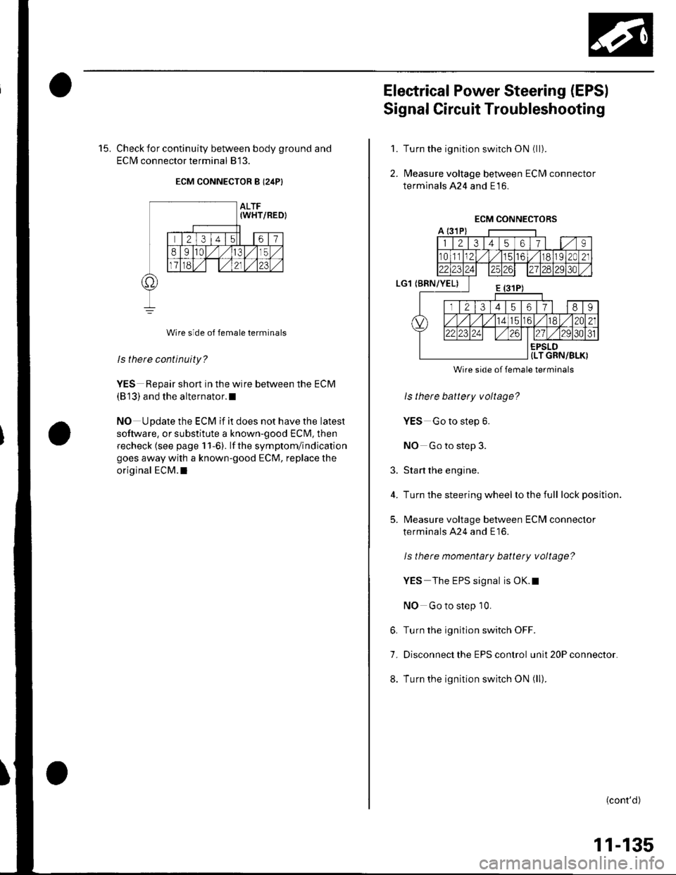
15. Check for continuity between body ground and
ECIM connector terminal 813.
ECM CONNECTOR B I24P}
Wire side of female terminals
ls there continuity?
YES Repair short in the wire between the ECM
(813) and the alternator.l
NO Update the ECM if it does not have the latest
software, or substitute a known-good ECM, then
recheck lsee page 1 1-6). lf the symptom/indication
goes away with a known-good ECM, replace the
original ECM.I
Electrical Power Steering (EPSI
Signal Circuit Troubleshooting
Turn the ignition switch ON (ll).
l\4easure voltage between ECM connector
terminals 424 and E16.
1.
2.
3.
4.
5.
Wire side of female terminals
ls there battery voltage?
YES Go to step 6.
NO Go to step 3.
Start the engine.
Turn the steering wheel lo the full lock position.
l\4easure voltage between ECM connector
terminals A24 and E16.
ls there momentaty battery voltage?
YES The EPS signal is OK.t
NO Go to step 10.
6. Turn the ignition switch OFF.
7. Disconnect the EPS control unit 20P connector.
8. Turn the ignition switch ON (ll).
(cont'd)
11-135
Page 343 of 1139
ldle Control System
Electrical Power Steering (EPSI Signal Circuit Troubleshooting (cont'd)
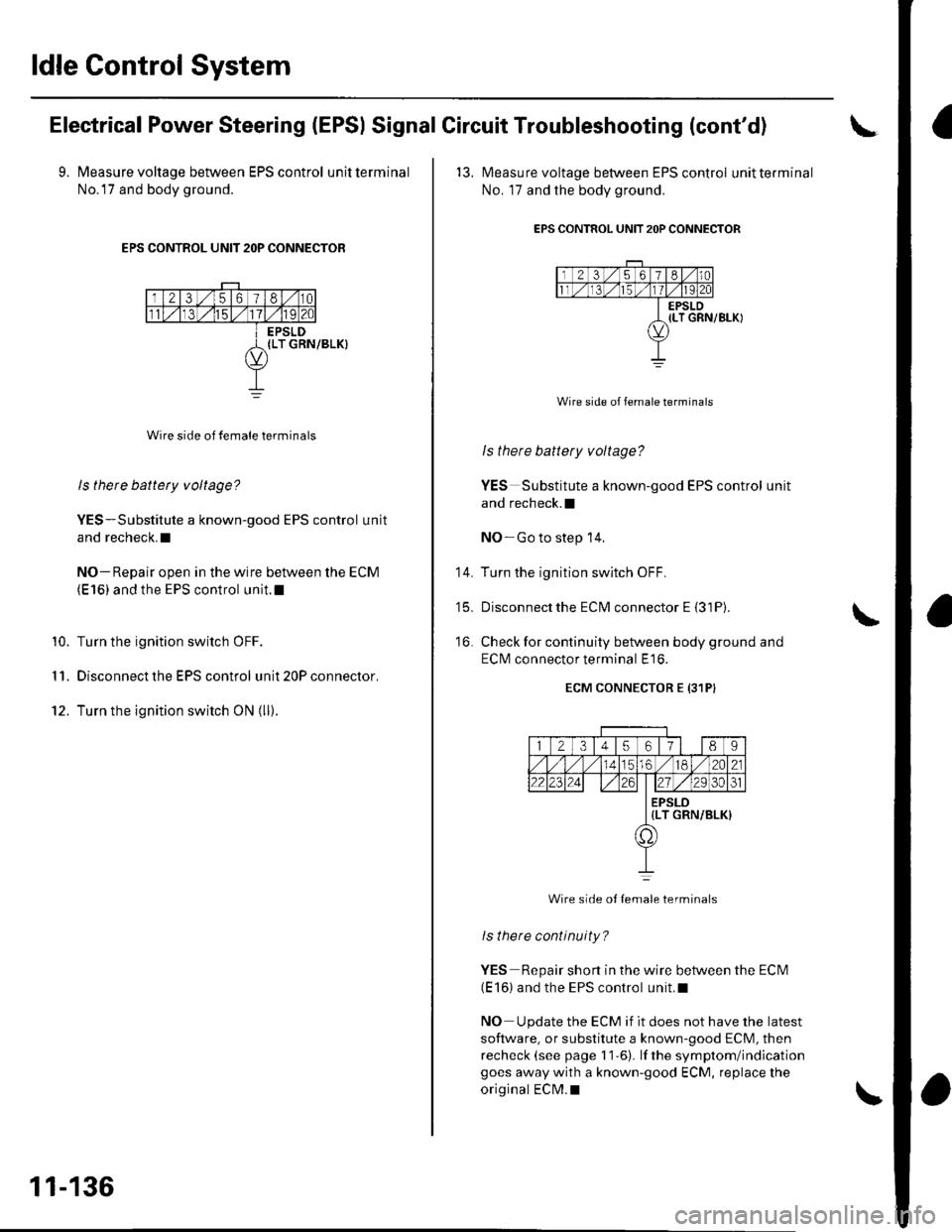
9. Measure voltage between EPS control unitterminal
No.l7 and body ground.
EPS CONTROL UNIT 2OP CONNECTOR
Wire side of female terminals
ls there battety voltage?
YES-Substitute a known-good EPS control unit
and recheck.I
NO- Repair open in the wire between the ECM(E 16) and the EPS control unit.l
Turn the ignition switch OFF.
Disconnect the EPS control unit 20P connector.
Turn the ignition switch ON (ll).
10.
I '�I.
12.
11-136
'13. l\4easure voltage between EPS control unitterminal
No. 17 and the body ground.
EPS CONTROL UNIT 2OP CONNECTOR
Wire side of female terminals
ls there battery voltage?
YES Substitute a known-good EPS control unit
and recheck.l
NO-Go to step 14,
Turn the ignition switch OFF.
Disconnectthe ECM connector E {31P).
Check for continuity between body ground and
ECI\4 connector terminal E16.
ECM CONNECTOR E {31PI
14.
t5_
16.
12345617l 189
56./182A21
2223zi ./29 30ol
EPSLD{LT GRN/BLK)
a,
Wire side ot Iemale terminals
lsthere continuity?
YES Repair short in the wire between the ECN4(E 16) and the EPS control unit.l
NO Update the ECM if it does not have the latest
software, or substitute a known-good ECM, then
recheck (see page 11-6). lf the symptom/indicationgoes away with a known-good ECM, replace the
original ECM.I
Page 363 of 1139
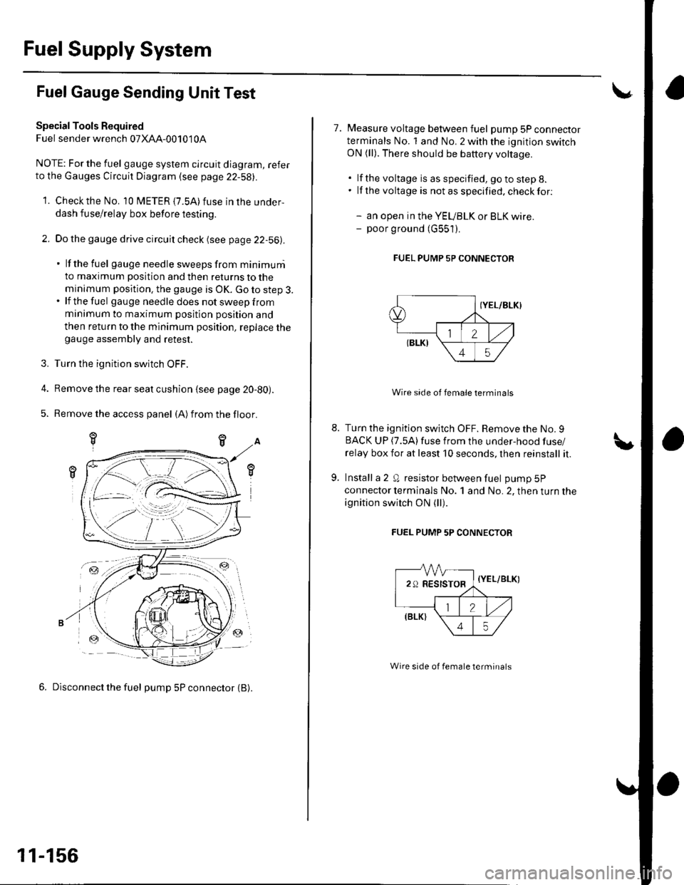
Fuel Supply System
Fuel Gauge Sending Unit Test
Special Tools Required
Fuel sender wrench 07XAA-001010A
NOTE; For the fuel gauge system circuit diagram, referto the Gauges Circuit Diagram (see page 22-58||.
1. Checkthe No. 10 fUETER {7.5A)fuse in the under-
dash fuse/relay box before testing.
2. Do the gauge drive circuit check (see page 22-56|l.
' lf the fuel gauge needle sweeps from minimuni
to maximum position and then returns to the
minimum position. the gauge is OK. Go to step 3.. lf the fuel gau ge need le does not sweep from
minimum to maximum position position and
then return to the minimum position, replace thegauge assembly and retest.
3. Turn the ignition switch OFF.
4. Remove the rear seat cushion {see page 20-80).
5. Remove the access panel (A)from the floor.
6. Disconnect the fuel pump 5P connector {B).
-ztr
11-156
7. Measure voltage between fuel pump 5P connectorterminals No. 1 and No. 2 with the ignition switchON (ll). There should be battery voltage.
. lf the voltage is as specified, go to step 8.. lf the voltage is notasspecified,checkfor:
- an open in the YEUBLK or BLK wire.- poor ground (G551).
FUEL PUMP 5P CONNECTOR
Wire side of female terminals
Turn the ignition switch OFF. Remove the No. 9BACK UP (7.5A)fuse from the under-hood fuse/
relay box for at least 10 seconds, lhen reinstall it.
Install a 2 Q resistor between fuel pump 5P
connector lerminals No. 1 and No. 2, then turn the
ignition switch ON (ll).
FUEL PUMP 5P CONNECTOR
-VVV-
29RESISTOR,
=-a
{Y
\
//,(elrt \
\45/
{YEL/BLK)
Wire side of female terminals
Page 374 of 1139
Catalytic Converter System
DTC Troubleshooting
DTC P0420: Catalytic System Efficiency
Below Threshold
NOTE: lf some of the DTCS listed below are stored at
the same time as DTC P0420, troubleshoot those DTCS
first, then recheck for DTC P0420.
P0137, P0138: Secondary Heated Oxygen Sensor(secondary HO2S) (Sensor 2)
P0141: Secondary HO2S (Sensor 2) heater
1. Reset the ECM {see page 1'l-4}, then continue to
step 2 through 5 to reset the readiness code.
2. Start the engine. Hold the engine at 3,000 rpm with
no load (in neutral) untilthe radiator fan comes on.
Drive for about l0 minutes without stopping. Your
speeo can vary.
With the transmission in 4th gear, drive at a steady
speed between 50 62 mph (80-'100 km/h) for
30 seconds.
Repeat step 4 three times. Between each repetition,
close the throttle completely for 1 2 seconds. lf
the engine is stopped during this part of the
procedure, repeat steps 3, 4 and 5.
Check for a Temporary DTC with the scan tool.
Does the scan tool indicate Temporaty DTC
P0420?
YES Check the TWC. lf necessary, replace the
TWC.I
NO Check for readiness code completion. lfthe
readiness is complete, it was a interminent failure,
and the system is OK at this time. lf the readiness
code is incomplete, repeat steps 2 through 5.1
4.
11-167
Page 406 of 1139
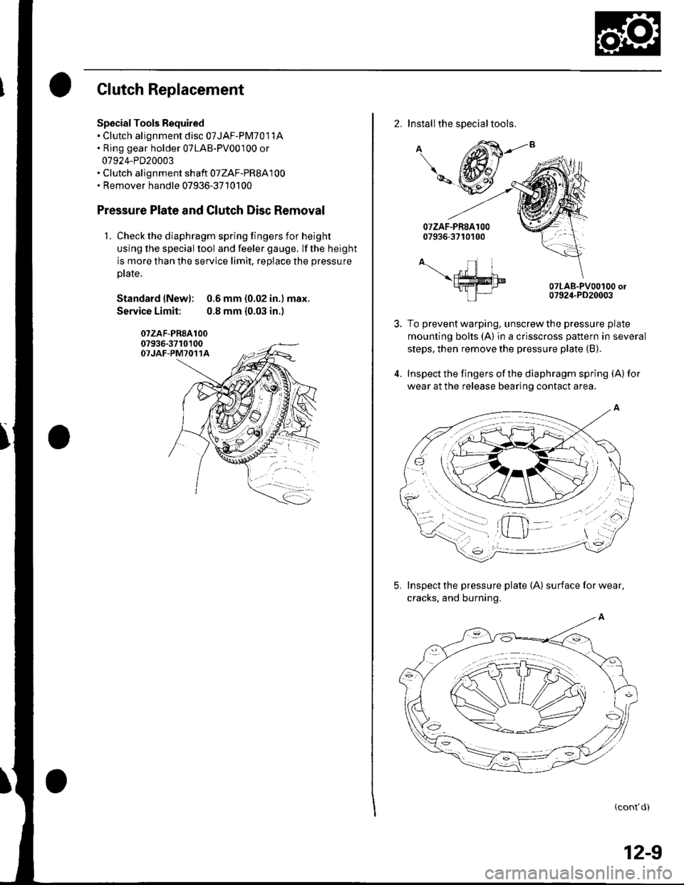
Clutch Replacement
Spscial Tools Required. Clutch alignment disc 07JAF-PM701 1A. Ring gear holder 07LAB-PV00100 or
07924-PD20003. Clutch alignment shaft 07ZAF-PR8A100. Remover handle 07936-3710100
Pressure Plate and Glutch Disc Removal
1. Check the diaphragm spring fingers for height
using lhe special lool and feeler gauge. lf the height
is more than the service limit, replace the pressure
ptate.
Standard lNewl: 0.6 mm (0.02 in.) max.
Service Limit: 0.8 mm {0.03 in.)
07zAF-PR8A10007936-3710100OTJAF-PM7O11A
2. Installthe special tools.
A
\-
A-.- nl I\ffim9fra-I tP|-
07LAB-PV00100 or07924-PD20003
To prevent warping, unscrew the pressure plate
mounting bolts (A) in a crisscross pattern in several
steps, then remove the pressure plate (B).
Inspect the fingers of the diaphragm spring (A) for
wear at the release bearing contact area.
5. Inspect the pressure plate 1A) surfaceforwear,
cracks. and burning.
(cont'd)
12-9
Page 408 of 1139
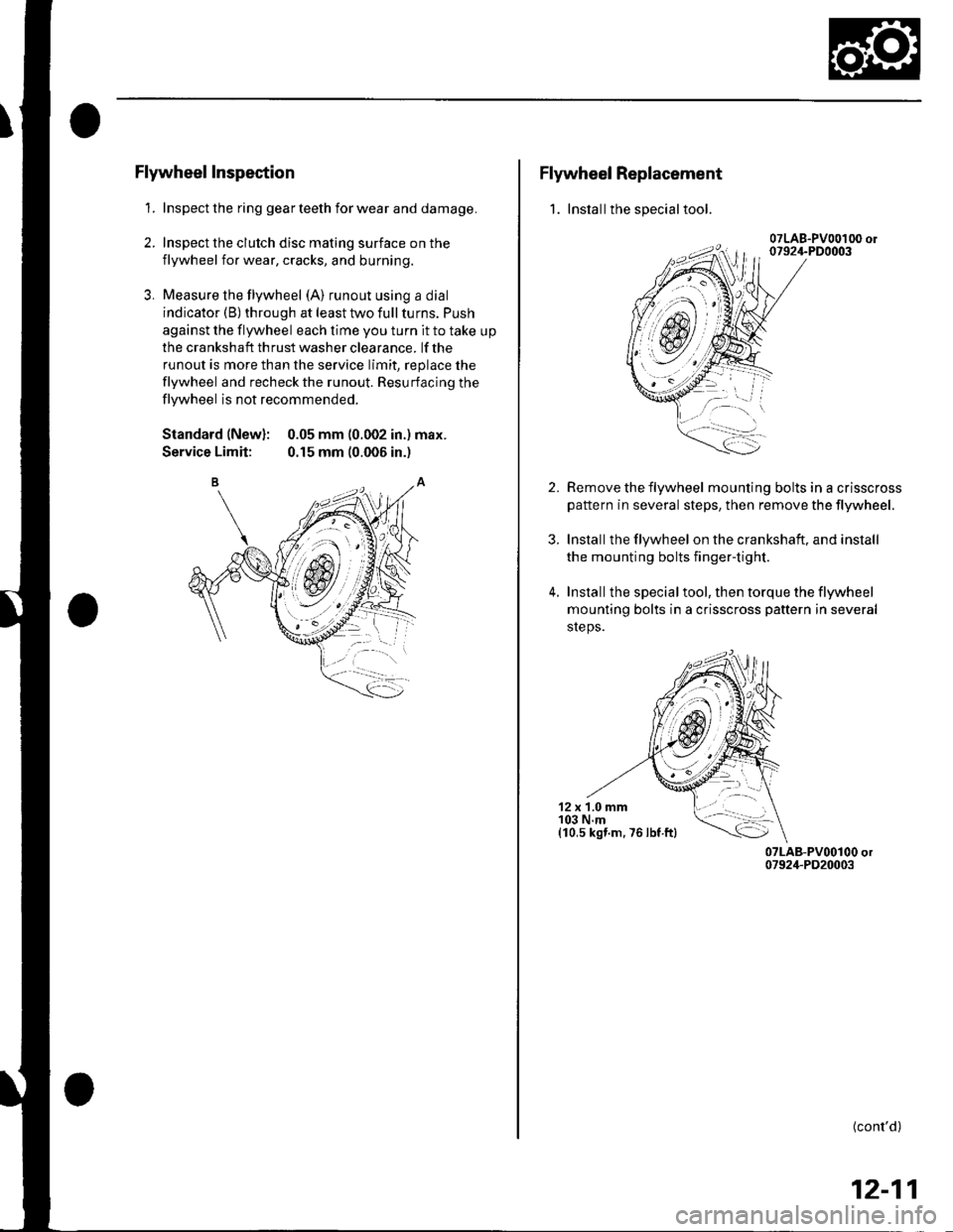
Flywheel Inspection
1. Inspect the ring gear teeth for wear and damage.
2. Inspect the clutch disc mating surface on the
flywheel for wear, cracks, and burning.
3. Measure the flywheel (A) runout using a dial
indicator (B) through at least two full turns. Push
against the flywheel each time you turn it to take up
the cra nksh aft th rust washer clea rance. lf the
runout is more than the service limit, replace the
flywheel and recheck the runout. Resurfacing the
flywheel is not recommended.
Standard (New): 0.05 mm (0.002 in.) max.
Service Limit: 0.15 mm (0.006 in.)
Flywheel Replacement
1. Installthe special tool.
2.
3.
4.
Remove the flywheel mounting bolts in a crisscross
pattern in several steps, then remove the tlywheel.
Installthe flywheel on the crankshaft, and install
the mounting bolts fingertight.
Installthe specialtool, then torque the flywheel
mounting bolts in a crisscross pattern in several
sreps.
12 x 1.0 mm103 N.m(10,s kst.m. 76 lbf ftl
(cont'd)
12-11
Page 409 of 1139
Glutch
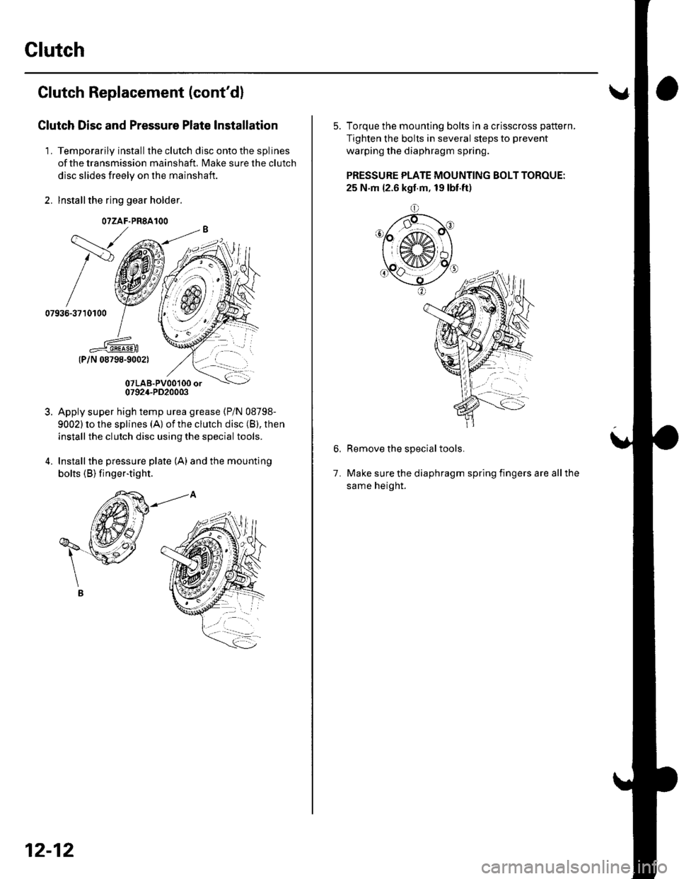
Clutch Replacement (cont'dl
Clutch Disc and Pressure Plate Installation
'L Temporarily install theclutch disc ontothesplines
of the transmission mainshaft, Make sure the clutch
disc slides freely on the mainshaft.
2. lnstallthe ring gear holder.
{P/N 08798-9002)
07LAB-PVo0'100 or0792,1-PD20003
Apply super high temp urea grease (P/N 08798-
9002) to lhe splines (A) of the clutch disc (B), then
install the clutch disc using the special tools.
Installthe pressure plate (A) and the mounting
bolts (B) finger-tig ht.
\---,
/v
07936-3710100
3.
O?ZAF.PRSAIOO
12-12
5. Torque the mounting bolts in a crisscross pattern,
Tighten the bolts in several steps to prevent
warping the diaphragm spring.
PRESSURE PLATE MOUNTING BOLT TOROUE:
25 N.m {2.6 kgt.m, 19 lbt.ft)
o
Remove the special tools.
Make sure the diaphragm spring fingers are all the
same height.
1.