EPS HONDA CIVIC 2002 7.G Workshop Manual
[x] Cancel search | Manufacturer: HONDA, Model Year: 2002, Model line: CIVIC, Model: HONDA CIVIC 2002 7.GPages: 1139, PDF Size: 28.19 MB
Page 43 of 1139
Starting System
Starter Performance Test
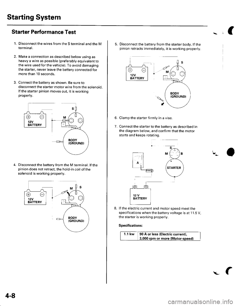
1,Disconnect the wires from the S terminal and the M
termrnal.
Make a connection as described below using as
heavy a wire as possible (preterably equivalent to
the wire used for the vehicle). To avoid damaging
the starter, never leave the battery connected for
more than 10 seconds,
Connect the battery as shown. Be sure to
disconnect the starter motor wire from the solenoid.
lf the starter pinion moves out, it is workingpropefly.
Disconnect the battery from the M terminal. lf thepinion does not retract, the hold-in coil of the
solenoid is working properly.
4-8
L
5. Disconnect the battery from the starter body. lfthepinion retracts immediately, it is working properly.
Clamp the starter firmly in a vise.
Connect the starter to the battery as described in
the diagram below, and confirm that the motor
sta rts and keeps rotating.
6.
7.
lf the eiectric cu rrent and motor speed meet the
specifications when the battery voltage is at 1 1.5 V,
the staner is working properly,
Specifications:
1.1 kw 90 A or less (Electric current),
ot more
Page 135 of 1139
Cylinder Head
8.
Cylinder Head lnstallation (cont'd)
7.Apply engine oil to the bolt threads and under thebolt heads of all the cylinder head bolts.
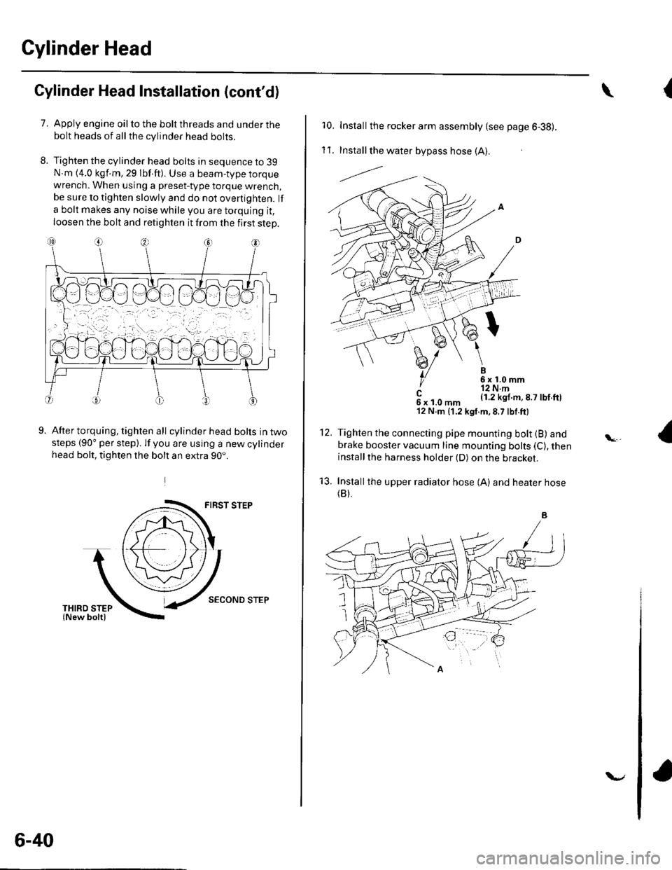
Tighten the cylinder head bolts in sequence to 39N.m {4.0 kgf.m, 29 lbf.ft). Use a beam-type torquewrench. When using a preset-type torque wrench,be sure to tighten slowly and do not overtighten. lf
a bolt makes any noise while you are torquing it,
loosen the bolt and retighten it from the first step.
9.After torquing, tighten all cylinder head bolts in twosteps (90" per step). lf you are using a new cylinderhead bolt, tighten the bolt an extra 90..
FIRST STEP
SECOND STEP
6-40
v
{\
10. Installthe rocker arm assembly {see page 6-38).
1't .Install the water bypass hose (A).
---l.-.
B6x1.0mm'r2 N.m(1.2 kgl.m,8.7 lbf.ftl
12.
't3.
c6xl.0mm'12 N,m (1.2 kgt.m,8.7 lbf.ft)
Tighten the connecting pipe mounting bolt (B) andbrake booster vacuum line mounting bolts (C), theninstallthe harness holder (D) on the bracket.
Installthe upper radiator hose {A) and heater hose(B).
Page 137 of 1139

Gylinder Head
Cylinder Head Gover Installation (cont'd)
Set the spark plug seals (A) on the spark plug tubes.
Once the cylinder head cover (B) is on the cylinderhead, slide the cover slightly back and forth to seat
the head cover gasket.
Inspect the cover washers (C). Replace any washer
that is damaged or deteriorated.
6-42
7. Tighten the bolts in two or three steps. In the final
step, tighten all bolts, in sequence, to 9.8 N.m (1.0
kgf.m, 7.2 lbf.ft).
8. Install the dipstick (A) and breather hose iB).
\
\l'
Page 165 of 1139
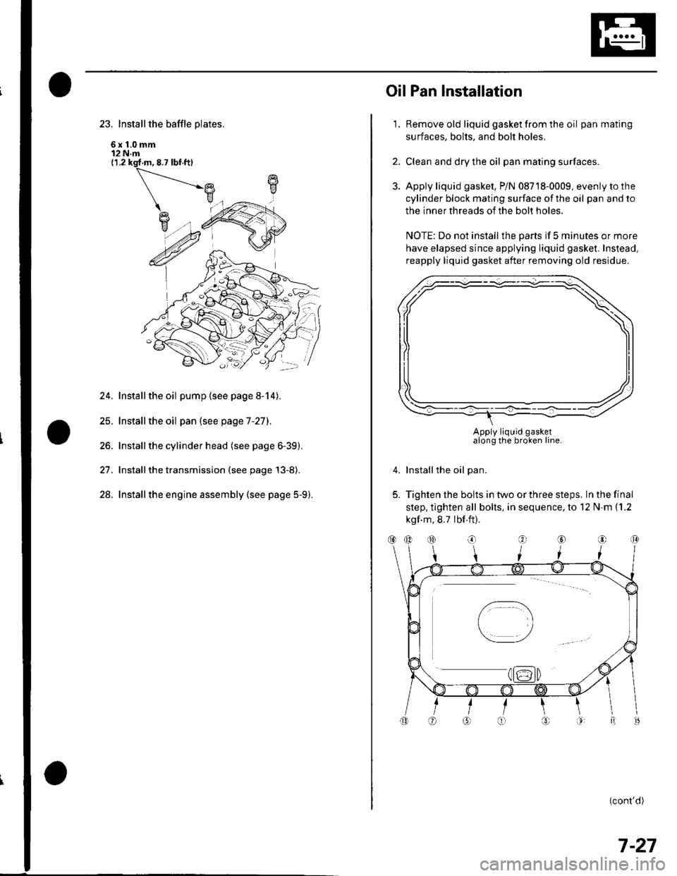
23. Install the baffle plates.
6x1.0mm12 N.m(1.2 ksf m, 8.7 lbf ft)
24. Installthe oil pump (see page 8-14).
25. Installthe oil pan (see page 7-27).
26. Installthe cylinder head (see page 6-39).
27. Installthe transmission (see page 13-8).
28. Installthe engine assembly (see page 5-9).
1.
OilPan lnstallation
Remove old liquid gasket from the oil pan mating
surfaces, bolts, and bolt holes.
Clean and dry the oil pan mating surfaces.
Apply liquid gasket, P/N 08718-0009, evenly to the
cylinder block mating surface of the oil pan and to
the inner threads of the bolt holes.
NOTE: Do not install the parts if 5 minutes or more
have elapsed since applying liquid gasket. Instead,
reapply liquid gasket after removing old residue.
Installthe oil pan.
Tighten the bolts in two or three steps. In the final
step, tighten all bolts, in sequence, to 12 N.m (1.2
kgf m, 8.7 lbf.ft).
(cont'd)
2.
3.
4.
5.
Apply liquid gasketalong the broken line.
(}@
7-27
Page 187 of 1139
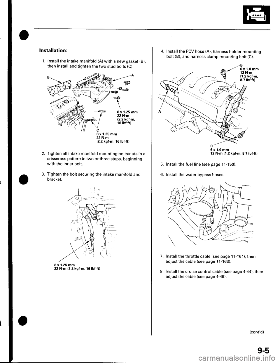
1. Install the intake manifold (A)with a new gasket (B),
then install and tighten the two stud bolts (C).
8 x 1.25 mm22 N.m|.2.2k91.m.16 tbt.ft)
8 x 1.25 mm22 N.rn(2.2 kgf m. 16 lbf.ttl
Tighten all intake manifold mountlng bolts/nuts in a
crisscross pattern in two or three steps, beginning
with the inner bolt.
Tighten the bolt securing the intake manifold and
bracket.
8 x 1.25 mm22 N.m (2.2 ksf m, 16lbf.ft)
*&
\
2.
?
w
4.
7.
5.
6.
Install the PCV hose {A), harness holder mounting
bolt (B), and harness clamp mounting bolt (C).
e-li*h,r
6x1.0mm12 N.m (1.2 kgf.m,8.7 lbf.ft)
Installthe fuel line (see page 11-150).
Installthe water bypass hoses.
Install the th rottle cable (see page 1 1-164), then
adjust the cable (see page 11-163).
Install the cruise control cable (see page 4-44). then
adjust the cable (see page 4-45).
8.
(cont'd)
9-5
Page 189 of 1139
1.
2.
3.
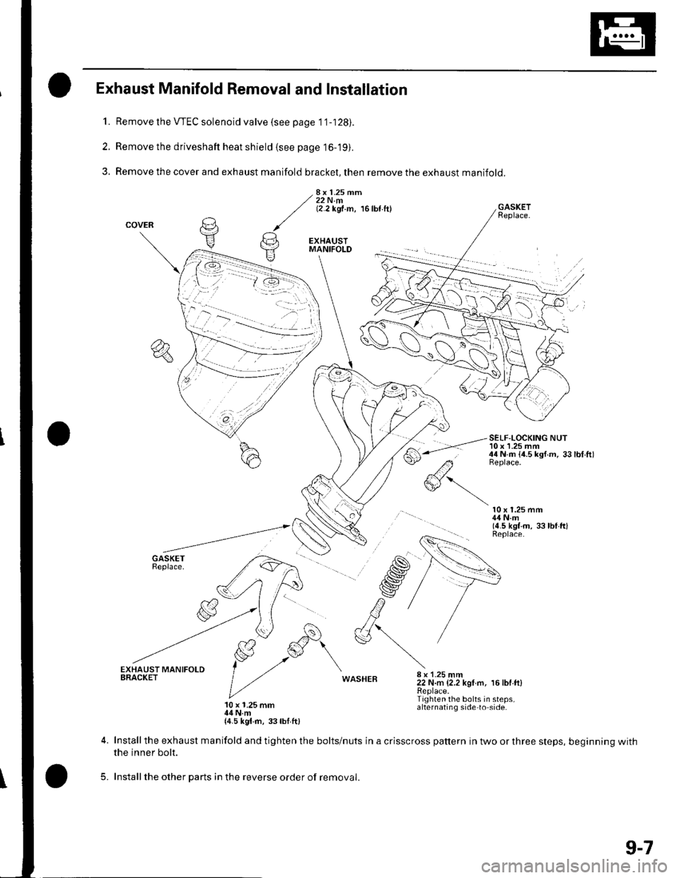
Exhaust Manifold Removal and Installation
Remove the VTEC solenoid valve (see page 1 '1-128).
Remove the driveshaft heat shield (see page 16-19).
Remove the cover and exhaust manifold bracket, then remove the exhaust manifold.
8x 1.25 mm22 N.m(2.2 kgf.m, 16lbt.ftl
#'-.-
GASKETReplace.
SELF-LOCKING NUT10 x 1.25 mm44 N.m {4.5 ksf.m, 33lbt.ftlBeplace.
10 x 1.25 mm44 N.m(4.5 kgt.m, 33 lbl ftlReplace.
WASHEB8 x 1-25 mm22 N.m (2.2 kgI m, 16lbf.ft)Replace.Tighten the bolts in steps,alternating side to side.10 x 1.25 mm14 N.m{4.5 kgl.rn, 33lbf.ft)
5.
Install the exhaust manifold and tighten the bolts/nuts in a crisscross pattern in two or three steps, beginning withthe inner bolt.
Installthe other parts in the reverse order of removal.
9-7
Page 190 of 1139
lntake Manifold and Exhaust System
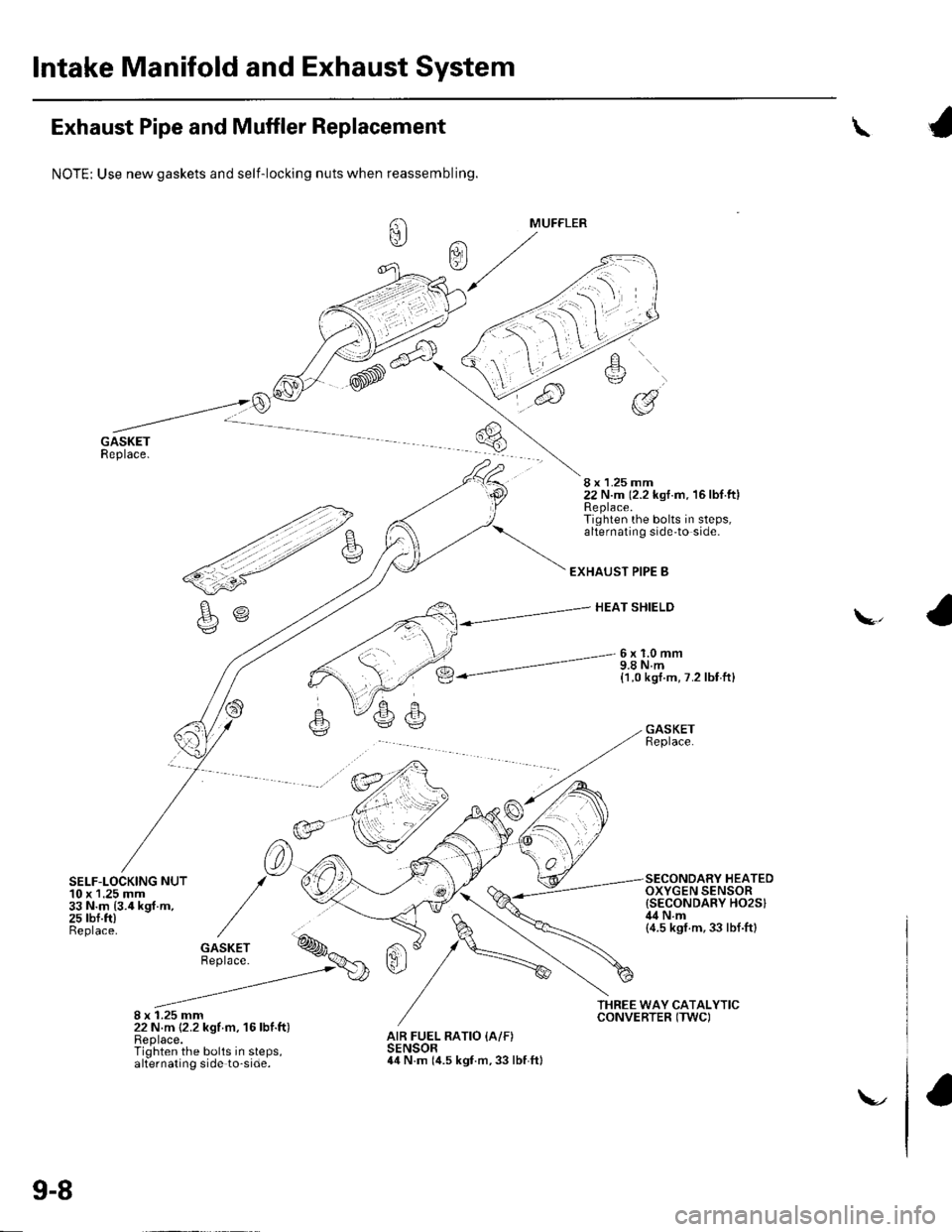
Exhaust Pipe and Muffler Replacement
SELF-LOCKING NUT10 x 1.25 mm33 N.m {3.4 kgf.m,25 rbf.ft)Beplace.
8 x 1.25 mm22 N.m {2.2 kgf m, 16lbf.ft)Replace.Tighten the bolts in steps,alternating side to-side.
\
NOTE: Use new gaskets and self-locking nuts when reassembling.
8 x 1.25 mm22 N.m (2.2 kst.m. 16lbf.ftlReplace.Tighten the bolts in steps,alternating side'to side.
EXHAUST PIPE B
HEAT SHIELD\,
6x1.0mm9.8 N.m{1.0 kgt.m, 7.2 lbf ft}
GASKETReplace.
SECONDARY HEATEDOXYGEN SENSOR{SECONDARY HO2SIil4Nm(4.5 ksf.m,33 lbf.ftl
AIR FUEL RATIO {A/F)SENSOR44 N.m (it.s kgf.m, 33 lbf ftl
9-8
\-.
Page 208 of 1139
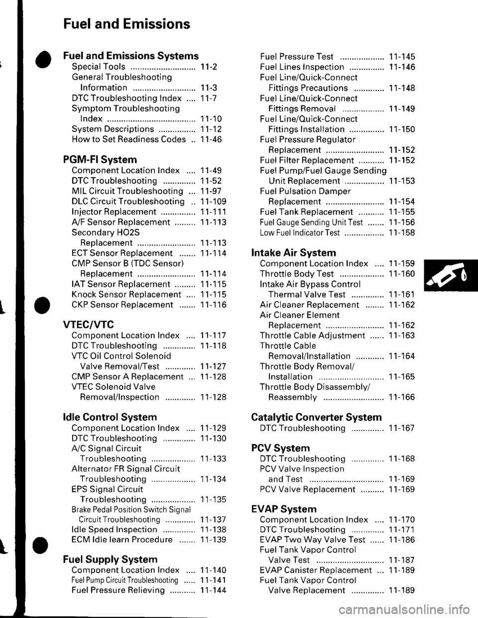
Fuel and Emissions
Fuel and Emissions Systems
SpecialTools
General Troubleshooting
Information
DTC Troubleshooting lndex ....
Symptom Troubleshooting
1ndex...............
System Descriptions ................
Howto Set Readiness Codes ..
PGM-FlSystem
Component Location Index ....
DTC Troubleshooting ..............
MIL Circuit Troubleshooting ...
DLC Circuit Troubleshooting ..
Injector Replacement ...............
A,/F Sensor Replacement .........
Secondary HO2S
Replacement
ECT Sensor Reolacement .......
CMP Sensor B {TDC Sensor)
Replacement
IAT Sensor Replacement .........
Knock Sensor Replacement ....
CKP Sensor Reolacement .......
VTEC/VTC
Comoonent Location Index ....
DTC Troubleshooting ..............
VTC Oil Control Solenoid
Valve Removal/Test .............
CMP Sensor A Replacement ...
VTEC Solenoid Valve
Removal/lnsoection .............
ldle Control System
Component Location Index
DTC Troubleshooting ..............
A,/C Signal Circuit
TroubleshootinS ...................
Alternator FR Signal Circu it
TroubleshootinS ...................
EPS Signal Circuit
TroubleshootinS ...................
Brake Pedal Position Switch Signal
Circuit Troubleshooting .............
ldle Speed Inspection
ECM ldle learn Procedure .......
Fuel Supply System
Component Location Index
Fuel Pump Circuit Troubleshooting
1't-2
I I-J
11-7
1 1-10
11-12
11-46
11-49
11-52
11-97
11-109
11-111
11-113
11-113
11-114
11-114
11-115
11-115
11-116
11-117
1 1-1 18
11-127
11-128
11-128
11-129
1I-130
I t- t55
11-134
1 1- 135
1 1-137
1 1-138
1 1-139
1 1-140
11-141
11-144
Fuel PressureTest ................... 11-145
Fuel Lines Inspection ............... 11-146
Fuel Line/Ouick-Connect
Fittings Precautions ............. 1 1-148
Fuel Line/Ou ick-Con nect
Fittings Removal .................. 1 1-149
Fuel Line/Ou ick-Con nect
Fittings lnstallation ............... 11-150
Fuel Pressure Regu lator
Replacement ......................... 11-152
Fuel Fifter Replacement ........... 11-152
Fuel Pump/Fuel Gauge Sending
UnitReDlacement ................. 11-153
Fuel Pulsation Damoer
Rep1acement ......................... 11-154
Fuel Tank Reolacement ........... 11-155
Fuel GaugeSending UnitTest ....... 11-156
Low Fuel lndicatorTest ................. 1 1-158
Intake Air System
Comoonent Location Index .... 11-159
Throttle BodyTest ................... 11-160
Intake Air Bypass Control
Thermal Valve Test .............. 11-161
Air Cleaner Reolacement ........ 11-162
Air Cleaner Element
Reolacement ......................... 11-162
Throttle Cable Adjustment ...... 11-163
Th rottle Cable
Removal/lnstallation ............ 1 1-164
Th rottle Body Removal/
Installation .. 11-165
Th rottle Body Disassembly/
Reassemblv .......................... 11-166
Catalytic Converter System
DTC Troubleshooting .............. 1 1-167
PCV System
DTC Troubleshooting .............. 1 1-168
PCV Valve InsDection
and Test ...... 1 1- 169
PCV Valve Reolacement .......... 11-169
EVAP System
Component Location Index .... 11-170
DTCTroubleshooting .............. 11-171
EVAP Two Way Valve Test ...... 11-186
Fuel Tank Vaoor Control
Valve Test ... 11-187
EVAP Canister Replacement ... 11-189
Fuel Tank Vaoor Control
Valve Reolacement .............. 1 1-189Fuel Pressu re Relieving ...........
Page 221 of 1139
Fuel and Emissions Systems
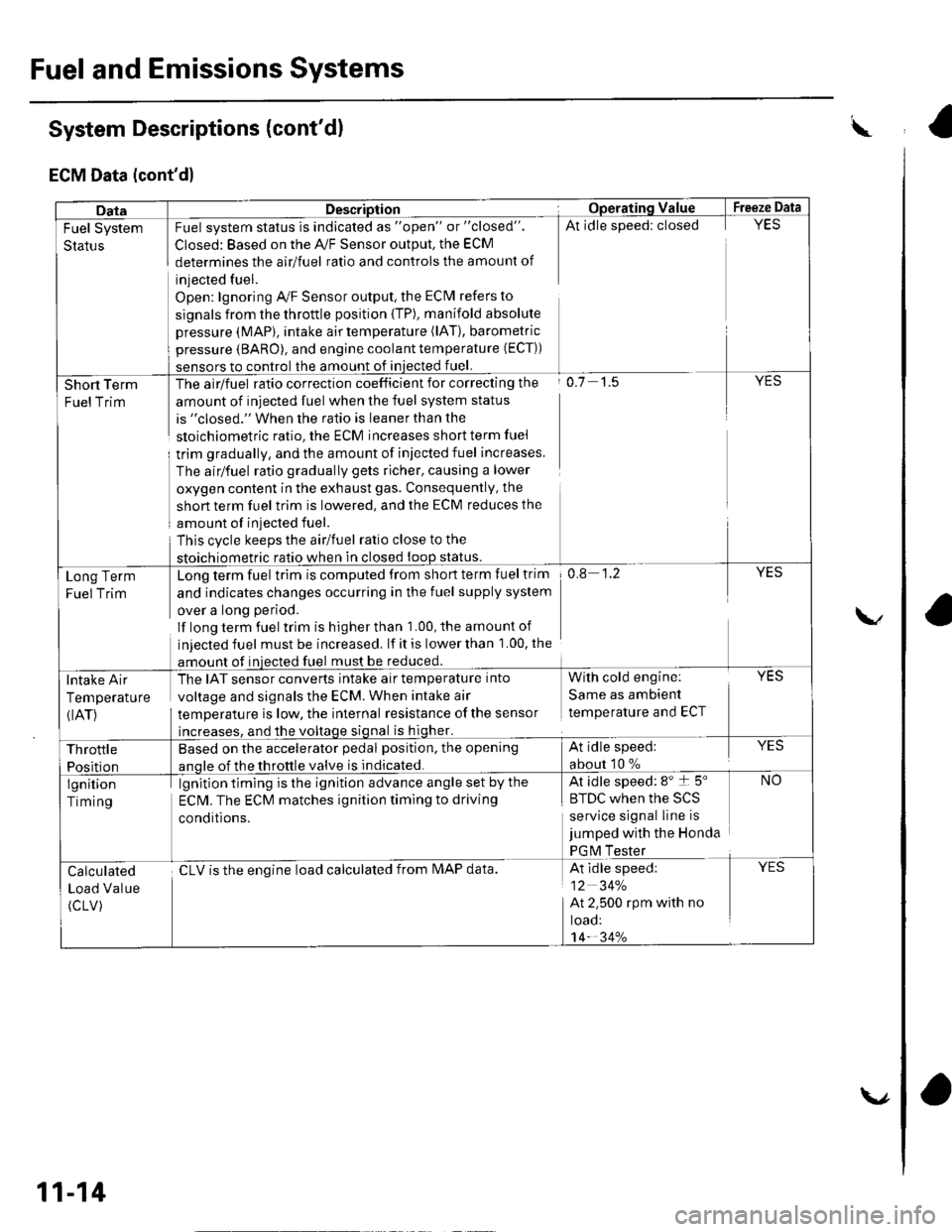
System Descriptions (cont'd)
ECM Data (cont'd)
w
DataDescriptionOpera'ting ValueFreeze Data
Fuel System
Status
Fuel system status is indicated as "open" or "closed".
Closed: Based on the A,/F Sensor output, the ECM
determines the airlfuel ratio and controls the amount of
injected fuel.
Open: lgnoring Ay'F Sensor output, the ECM refers to
signals from the throttle position {TP), manifold absolute
pressure (MAP), intake air temperature (lAT), barometric
pressure (BARO), and engine coolant temperature (ECT))
sensors to control the amount of iniected fuel.
At idle speed: closedYES
Short Term
FuelTrim
The airlfuel ratio correction coefficient for correcting the
amount of injected fuel when the fuel system status
is "closed." When the ratio is leaner than the
sloichiometric ratio, the ECM increases short term fuel
trim gradually, and the amount of iniected fuel increases.
The airlfuel ratio gradually gets richer, causing a lower
oxygen content in the exhaust gas. Consequently, the
short term fuel trim is lowered, and the ECM reduces the
amount of injected fuel.
This cvcle keeps the airlfuel ratio close to the
stoichiometric ratio when in closed loop status.
o.7 1.5YES
Long Term
Fuel Trim
Long term fuel trim is computed from short term fuel trim
and indicates changes occurring in the fuel supply system
over a long period.
lf long term fuel trlm is higher than 1.00, the amounl of
injected fuel must be increased. lf it is lower than 1.00, the
amount of injected fuel must be reduced.
0.8 1.2YES
Intake Air
Temperature
{IAT)
The IAT sensor converts intake air temperature into
voltage and signals the ECM. When intake air
temperature is low, the internal resistance ofthe sensor
increases, and the voltage signal is higher.
With cold engine:
Same as ambient
temperature and ECT
YES
Throttle
Position
Based on the accelerator pedal position, the opening
anole of the throttle valve is indicated.
At idle speed:
about 10 %
YES
lgnition
Timing
lgnition timing is the ignition advance angle set by the
ECM. The ECM matches ignition timing to driving
conditions.
At idle speed: 8" t 5"
|' tuL wnen rne >L)
service signal line is
jumped with the Honda
PGM Tester
NO
Calculated
Load Value
(cLV)
cLV is the enoine load calculated from IMAP data.At idle speed:
12 34%
At 2.500 rpm with no
toao:'t4- 34%
YES
11-14
\.,
ra
Page 225 of 1139
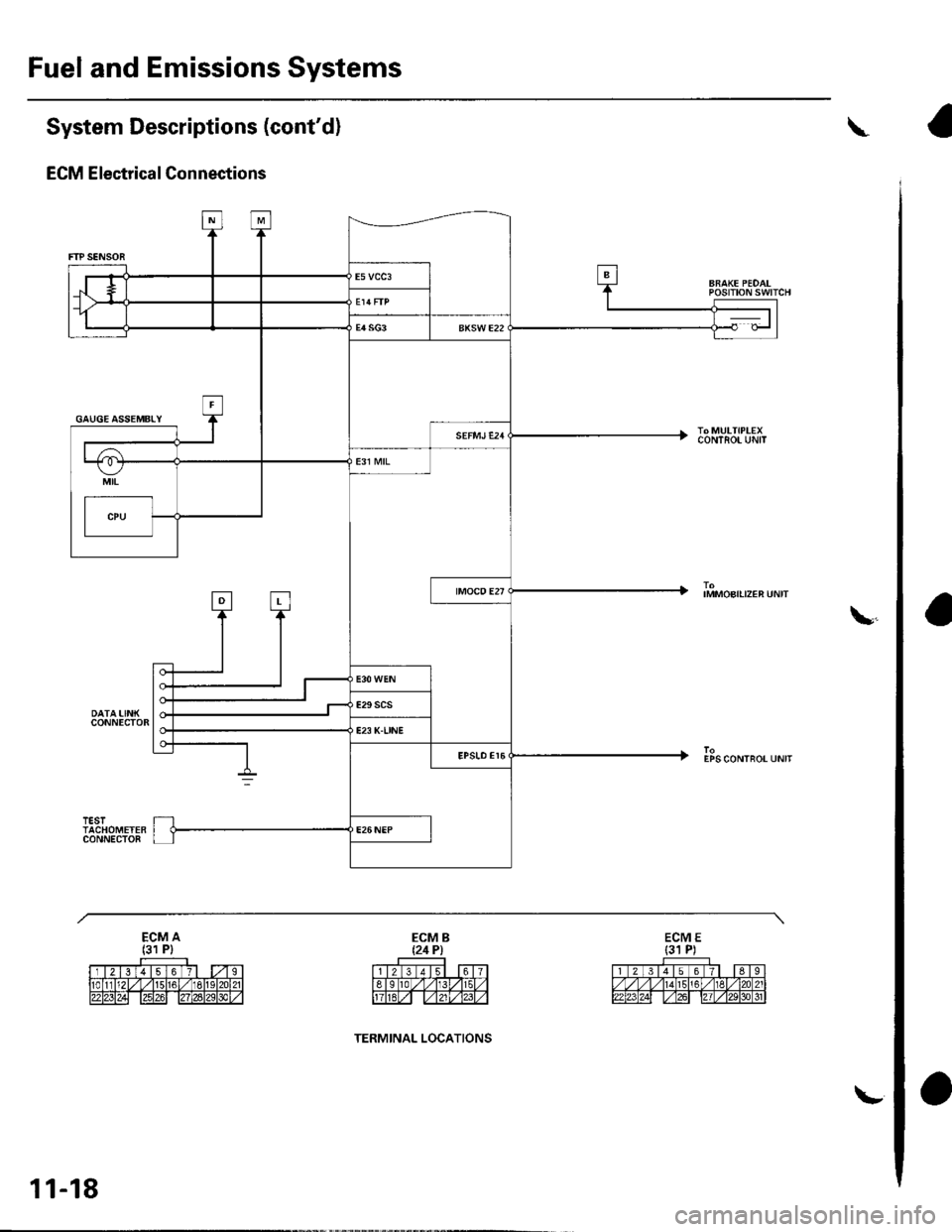
Fuel and Emissions Systems
System Descriptions (cont'd)
ECM Electrical Connections
\
ARAKE PEDALPOStTtON SWTTCH
IMMOBILPEN UN|T
EPS CONTROT UNIT
\
GAUGE ASSEMBLY
11-18
TERMINAL LOCATIONS
\-