EPS HONDA CIVIC 2002 7.G Owner's Manual
[x] Cancel search | Manufacturer: HONDA, Model Year: 2002, Model line: CIVIC, Model: HONDA CIVIC 2002 7.GPages: 1139, PDF Size: 28.19 MB
Page 453 of 1139
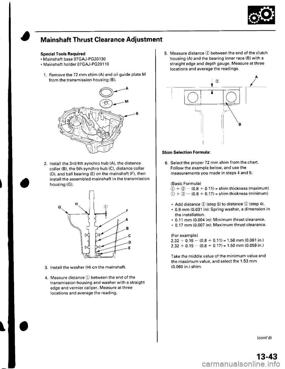
Mainshaft Thrust Clearance Adiustment
Special Tools Required. Mainshaft base 07GAJ-PG20130. Mainshaft holder 07GAJ-PG20110
1. Remove the 72 mm shim (A) and oilguide plate M
from the transmission housing (B).
,5---ov/
Installthe 3rd/4th synchro hub (A), the distance
collar (B), the 5th synchro hub {C). distance collar
(D), and ball bearing (E) on the mainshaft (F), then
installthe assembled mainshaft in the transmission
housing (G).
lnstall the washer (H) on the mainshaft.
Measure distance O between the end of the
transmission housing and washer with a straight
edge and vernier caliper. Measure at three
locations and average the reading.
5.Measure distance @ between the end of the clutch
housing (A) and the bearing inner race (B)with a
straight edge and depth gauge. Measure at three
locations and average the readings.
A
Shim Selection Formula:
6, Select the proper 72 mm shim from the chan.
Follow the example below, and use the
measurements you made in steps 4 and 5:
(Basic Formula)
O+@ (0.8 * 0.11) = shim thickness (maximum)
O + O (0.8 + 0.17) = shim thickness (minimum)
. Add distance O (step 5) to distance O (step 4)
. 0.8 mm (0.031 in): Spring washer, a dimension in
the installation.. 0.11 mm (0.004 in): lvlinimum thrust clearance
. 0.17 mm (0.007 in): Maximum thrust clearance.
(For example)
2.32 + 0.15 - (0.8 + 0.11)= 1.56 mm (0.061 in.)
2.32 + 0.15 - (0.8 + 0.17)= 1.50 mm (0.059 in.)
Take the middle value of the minimum value and
the maximum value, and select the 1.53 mm
(0.060 in.) shim.
{cont'd)
13-/li|
Page 463 of 1139
\
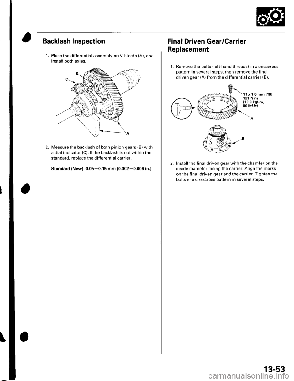
Backlash lnspection
1.Place the differential assembly on V-blocks (A), and
install both axles.
Measure the backlash of both pinion gears (B) with
a dial indicator (C). lf the backlash is not within the
standard, replace the differential carrier.
Standard (New): 0.05 0.15 mm (0.002 0.006 in.)
Final Driven Gear/Carrier
Replacement
1. Remove the bolts (left-hand threads) in a crisscross
pattern in several steps, then remove the final
driven gear (A)from the differential carrier {B).
t x t.o mm {to)121 Nm(12.3 kgf m,89 rbt.ft)
Install the final driven gear with the chamfer on the
inside diameter facing the carrier. Align the marks
on the final driven gear and the carrier. Tighten the
bolts in a crisscross pattern in several steps.
13-53
Page 466 of 1139
M/T Differential
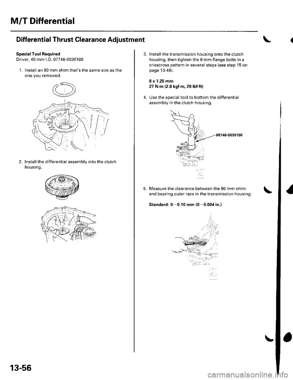
Differential Thrust Clearance Adjustment
SpecialTool Required
Driver. 40 mm LD. 07746-0030100
1. Install an 80 mm shim that's the same size as the
one you removeo.
2.Install the differential assembly into the clutch
housing.
13-56
5.
Install the transmission housing onto the clutch
housing, then tighten the 8 mm flange bolts in a
crisscross pattern in several steps (see step 15 on
page 13-48).
8 x 1.25 mm
27 N m (2.8 kgf'm, 20 lbf.ft)
Use the special toolto bottom the differential
assembly in the clutch housing.
00746-0030100
Measure the clearance between the 80 mm shim
and bearing outer race in the transmission housing.
Standard: 0 0.10 mm l0 0.004 in.)
-i.w.t ..1-- -- :,- -=.
Page 481 of 1139
Driveline/Axle
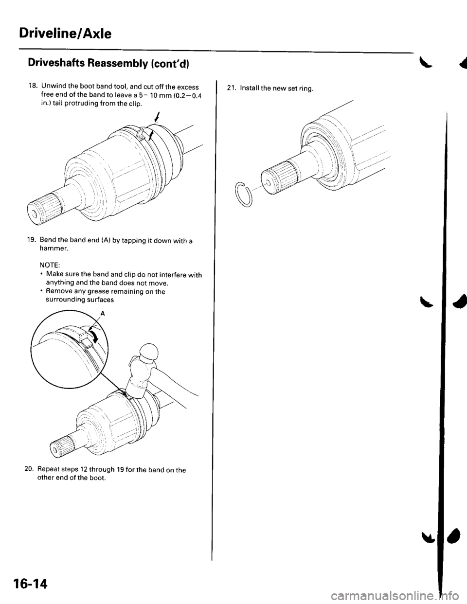
Driveshafts Reassembly (cont'dl
18. Unwind the boot band tool, and cut off the excessfree end of the bandto leave a 5- 10 mm (0.2-0.4
in.) tail protruding from the clip
19. Bend the band end (A) by tapping it down with anammer.
NOTE;. Make sure the band and clip do not interfere withanything and the band does not move.. Remove any grease remaining on the
surrounding surfaces
20. Repeat steps 12 through 19 for the band on theother end of the boot.
16-14
{
2'1. Installthe new set ring.
Page 484 of 1139
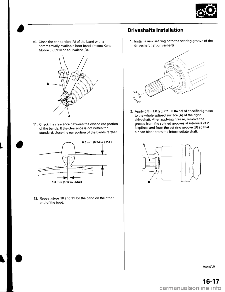
10. Close the ear portion (A) of the band with a
commercially available boot band pincers Kent-
Moore J-35910 or equivalent (B).
Check the clearance between the closed ear portlon
of the bands. lf the clearance is not within the
standard, close the ear podion of the bands farther.
11.
12.Repeat steps 10 and 11 for the band on the other
end of the boot.
6.0 mm 10.24 in.) MAX
3.0 mm {0.12 in.} MAX
Driveshafts Installataon
1. Install a new set ring onto the set ring groove of the
driveshaft {left driveshaft ).
Apply 0.5 1.0 g {0.02 0.04 oz) of specified grease
tothewhole splined surface (A) ofthe right
driveshaft. After applying grease, remove the
grease from the splined grooves at intervals of 2-
3 splines and from the set ring groove (B) so that
air can bleed from the intermediate shaft.
(cont'd)
16-17
Page 493 of 1139
Steering
Steering
Special Tools ............. 17-2
Comoonent Location Index ......................................... 17-3
Steering Wheel Rotational Play Check .....................". 17-4
Power Assist Check .................. .......... 17-4
Steering Linkage and Gearbox Inspection ................. 17-5
Steering Wheel Removal .........................,................... 17-6
Steering Wheel Disassembly/Reassembly ................ 17-7
Steering Wheel Installation ............... 17-8
Steering Column Removal and Installation ...........'... 17-9
Steering Column Inspection .............. 17-11
Steering Lock Replacement .......................................'. 17-'12
Rack Guide Adiustment ....."........'..'.. 17-13
Electrical Power Steering (EPS)17-15
Page 496 of 1139
Steering
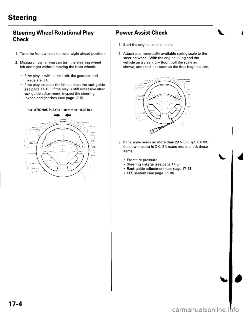
Steering Wheel Rotational Play
Check
1. Turn the front wheels to the straight ahead position.
2. Measure how far you can turn the steering wheel
left and right without moving the front wheels.
. lf the play is within the limit, the gearbox and
linkage are OK.. lf the playexceedsthe limit, adjustthe rack guide
{see page '17-13). lf the play is still excessive after
rack guide adjustment, inspect the steering
linkage and gearbox {see page 17-5).
BOTATIONAL PLAY: 0 10 mm (0-0.39 in.l
+:
17-4
Power Assist Check
Start the engine, and let it idle.
Attach a commercially available spring scale to the
steering wheel. With the engine idling and the
vehicle on a clean, dry floor, pull the scale as
shown, and read it as soon as the tires begin to turn.
\
1.
3. lf the scale reads no morethan 29 N (3.0 kgf,6.6 lbf),
the power assist is OK. lf it reads more, check these
items:
. Front tire pressure. Steering linkage (see page 17-5). Rack gulde adjustment (see page 17-13). EPS system (see page 17-18)
Page 506 of 1139
Electrical Power Steering (EPSI
SpecialTools ............. 17 -16
Component Location Index ......................................... 17-17
General Troubleshooting Information ....................... 17-18
DTC Troubleshooting Index .............. 17-22
Symptom Troubleshooting Index ............................... 17 -23
System Description ................. ........... 17-24
Circuit Diagram ......... 17-26
DTC Troubleshooting ............... .......... 17-28
EPS lndicator Circuit Troubleshooting ....................... 17-47
Motor Removal/lnstallation ............... 17-49
Steering Gearbox Removal ............... 17-51
Steering Gearbox Overhaul ............... 17-55
Steering Gearbox Installation ........... 17-63
EPS Control Unit Remova l/lnsta llation ....................... 17-67
Tie-rod Ball Joint Boot Replacement .......................... 17-67
Page 507 of 1139
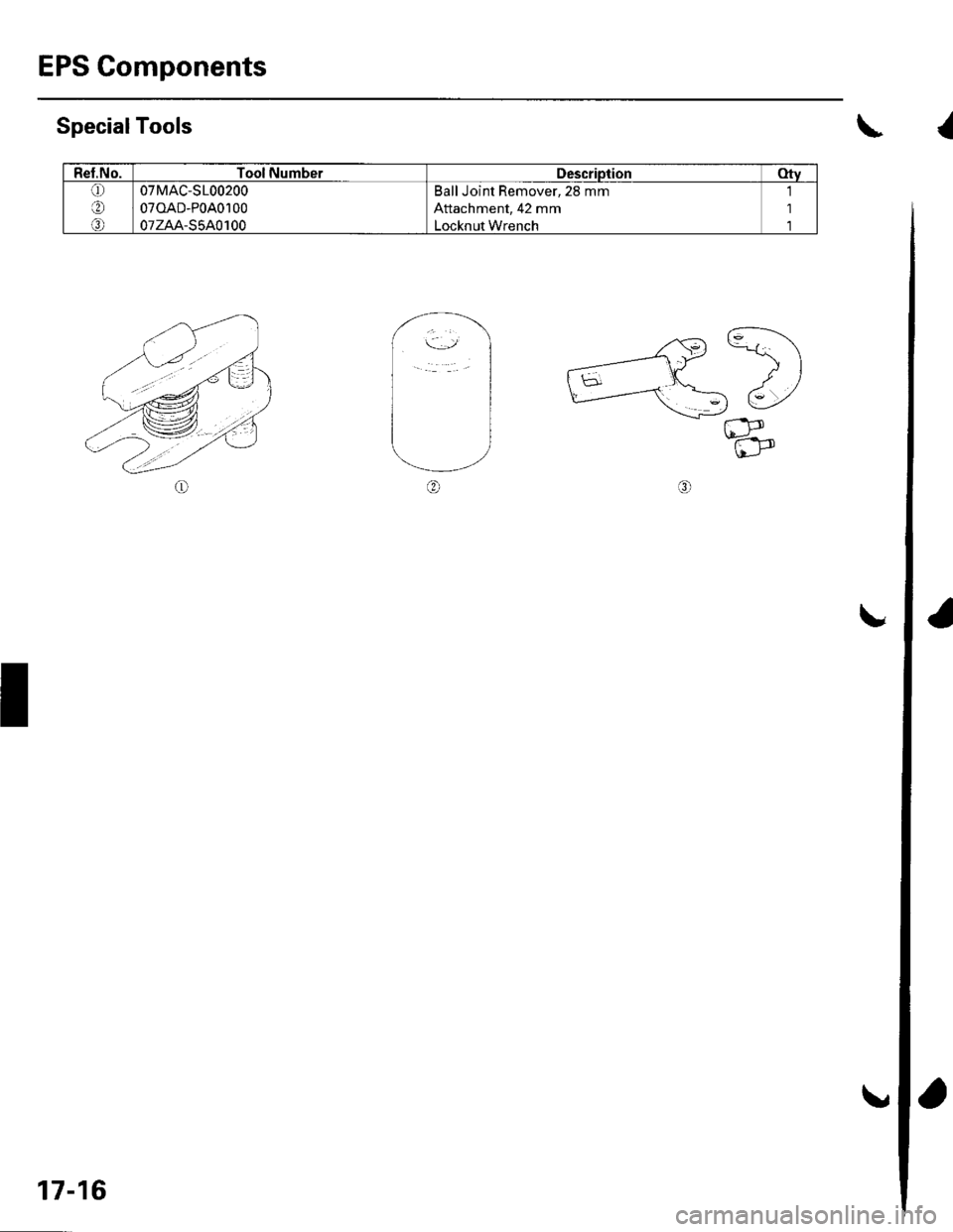
EPS Components
Rel.No.Tool NumberDescriptionotv(!)
at'
o
07MAC-S100200
070AD-P0A0100
07zAA-S5A0100
Ball Joint Remover, 28 mm
Attachment, 42 mm
Locknut Wrench
'1
1'l
SpecialTools\
,.^G) C\
_---1t
-)
)
h5--d-'
u_r-.c_-tt)\L-,
t
I
17-16
a
Page 508 of 1139
![HONDA CIVIC 2002 7.G Owners Manual Component Location Index
UNDER.HOODFUSE/RELAY BOX
EPS CONTROL UNITEPS Control Unit Removal/lnstallation,page 17 -67
UNDER.DASH FUSE/RELAY BOX
-,/.,....
.,i,
X ]
DATA LINK CONNECTOR I16P)
TOROUE SENS HONDA CIVIC 2002 7.G Owners Manual Component Location Index
UNDER.HOODFUSE/RELAY BOX
EPS CONTROL UNITEPS Control Unit Removal/lnstallation,page 17 -67
UNDER.DASH FUSE/RELAY BOX
-,/.,....
.,i,
X ]
DATA LINK CONNECTOR I16P)
TOROUE SENS](/img/13/5744/w960_5744-507.png)
Component Location Index
UNDER.HOODFUSE/RELAY BOX
EPS CONTROL UNITEPS Control Unit Removal/lnstallation,page 17 -67
UNDER.DASH FUSE/RELAY BOX
-,'/.,....
'.,i,
X ]
DATA LINK CONNECTOR I16P)
TOROUE SENSOR
STEERING GEARBOXSteering Gearbox Removal, page 17-51Steering Gearbox Overhaul, page 17-55Steering Gearbox Installation, page 17-63
Removal/lnstallation,page l7-49
GAUGE ASSEMBLY
MOTOR
17-17