service HONDA CIVIC 2002 7.G Owner's Manual
[x] Cancel search | Manufacturer: HONDA, Model Year: 2002, Model line: CIVIC, Model: HONDA CIVIC 2002 7.GPages: 1139, PDF Size: 28.19 MB
Page 48 of 1139
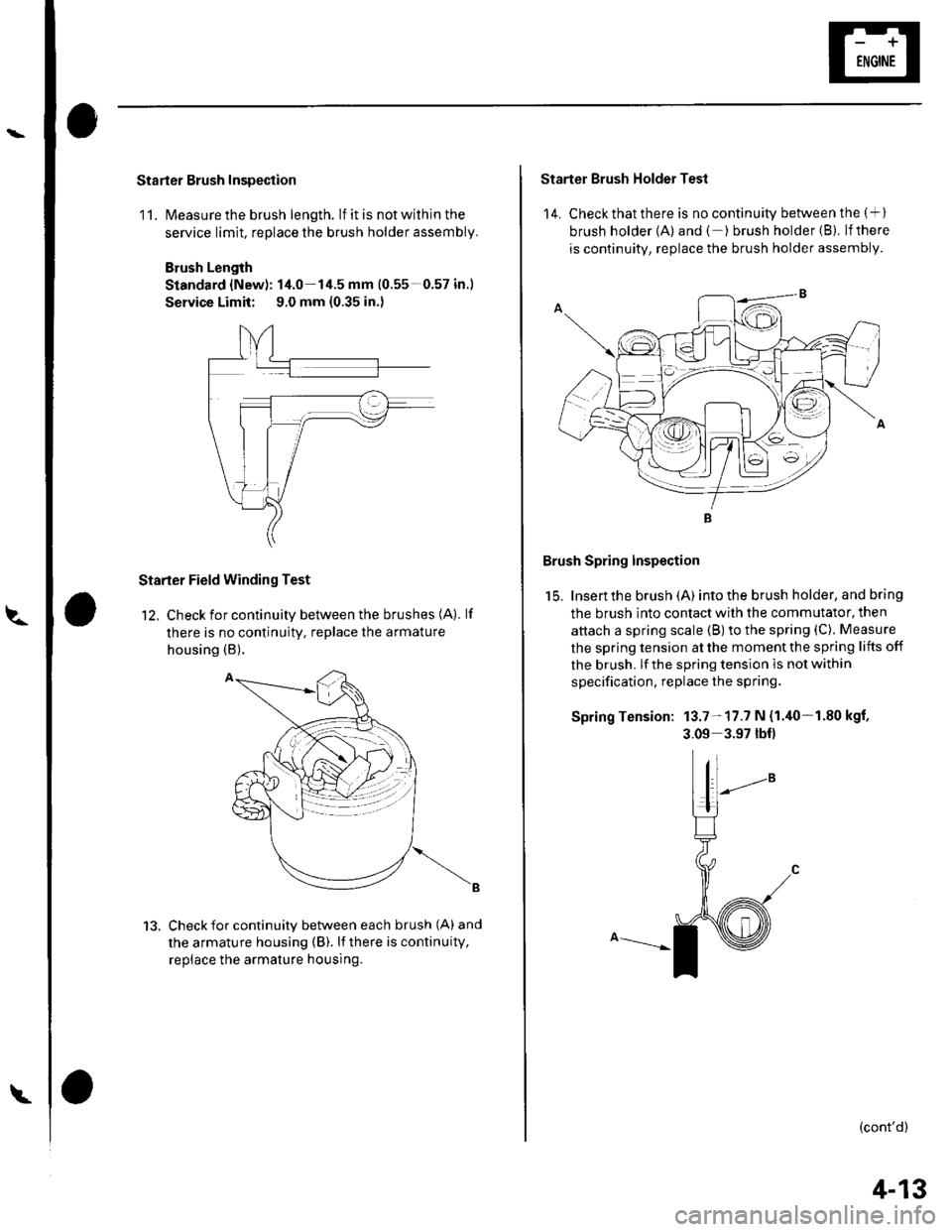
Starter Brush Inspection
11. lvleasure the brush length. lf it is not within the
service limit, replace the brush holder assembly.
Brush Length
Standard {New): 14.0-14.5 mm (0.55-0.57 in.)
Service Limit: 9.0 mm {0.35 in.)
Starter Field Winding Test
12. Check for continuity between the brushes (A). lf
there is no continuity. replace the armature
housing (B).
Check for continuity between each brush (A) and
the armature housing (B). li there is continuity,
replace the armature housing.
13.
Starter Brush Holder Test
14, Check that there is no continuity between the (+ )
brush holder {A) and ( ) brush holder (B}. lfthere
is continuity, replace the brush holder assembly.
Brush Spring Inspection
15. Insen the brush (A) into the brush holder, and bring
the brush into contact with the commutator, then
attach a spring scale (B) to the spring (C). Measure
the spring tension at the moment the spring lifts off
the brush. lf the spring tension is not within
specification, replace the spring.
Spring Tension: 13.7-17.7 N {1.40-1.80 kgf,
3.09 3.97 lbf)
(cont'd)
4-13
Page 52 of 1139
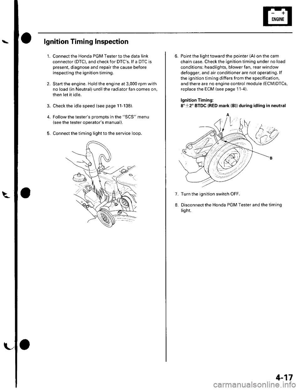
lgnition Timing Inspection
1.
4.
5.
Connect the Honda PGM Tester to the data link
connector (DTC), and check for DTC'S. lf a DTC is
present, diagnose and repair the cause before
inspecting the ignition timing.
Startthe engine. Hold the engine at 3,000 rpm with
no load (in Neutral) until the radiator fan comes on,
then let it idle.
Check the idle speed (see page 11-138).
Follow the tester's prompts in the "SCS" menu
{see the tester operator's manual),
Connect the timing light to the service loop.
o
6. Point the light toward the pointer (A) on the cam
chain case. Check the ignition timing under no load
conditions: headlights, blower fan. rear window
defogger, and air conditioner are not operaling. lf
the ignition timing differs from the specification,
and there are no engine control module {ECM)DTcs,
replace the ECM (see page 11-4)
lgnition Timing:
8"+2" BTDC {RED mark {B)) during idling in neutral
A
7. Turn the ignition switch OFF.
Disconnectthe Honda PGM Tester and thetiming
light.
4-17
Page 54 of 1139
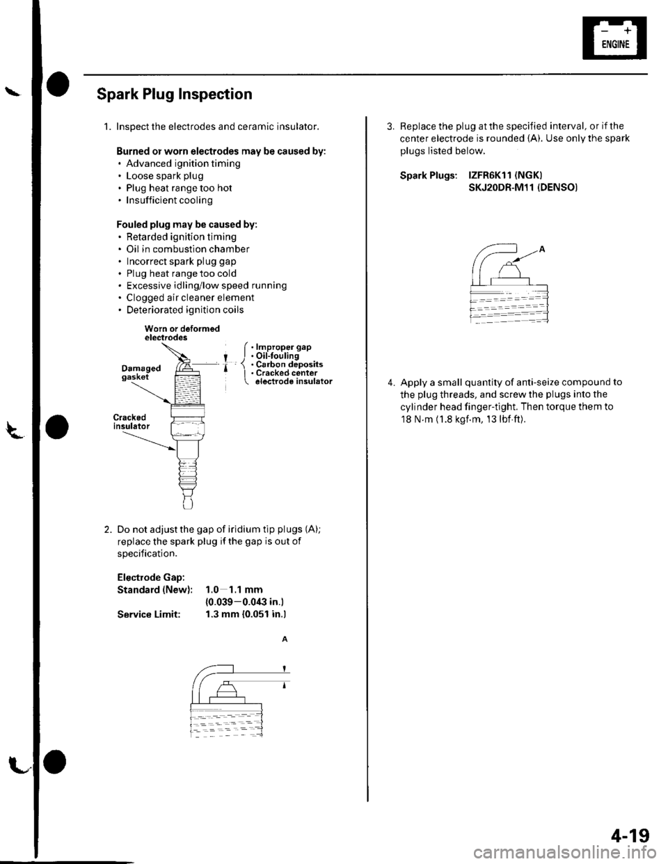
Spark Plug Inspection
1.Inspect the electrodes and ceramic insulator.
Burned or worn electrodes may be caused by:. Advanced ignition timing. Loose spark plug
. Plug heat range too hot.Insufficientcooling
Fouled plug may be caused by:. Retarded ignition timing. Oil in combustion chamber. Incorrect spark plug gap
. Plug heat range too cold. Excessive idling/low speed running. Clogged air cleaner element. Deteriorated ignition coils
Worn or deformedelectrodes
Do not adjust the gap of iridium tip plugs (A);
replace the spark plug if the gap is out of
specification.
Electrode Gap:
Standard (New): 1.0 1.1 mm
{0.039-0.0€ in.)
Service Limit: 1.3 mm {0.051 in.l
f .lmproper gap
I J.Oil-toulingr- 1 . Cs6on deposits' I . Cracked center electrode insulator
L
3. Replace the plug at the specified interval, or if the
center electrode is rounded {A). Use onlV the spark
plugs listed below.
Spark Plugs: lZFR6Kl1 (NGK)
SKJ2ODR-M11 (DENSO)
Apply a small quantity of anti-seize compound to
the plug threads, and screw the plugs into the
cylinder head finger-tight. Then torque them to
18 N m (1.8 kgf.m, 13lbf ft).
4.
4-19
Page 69 of 1139
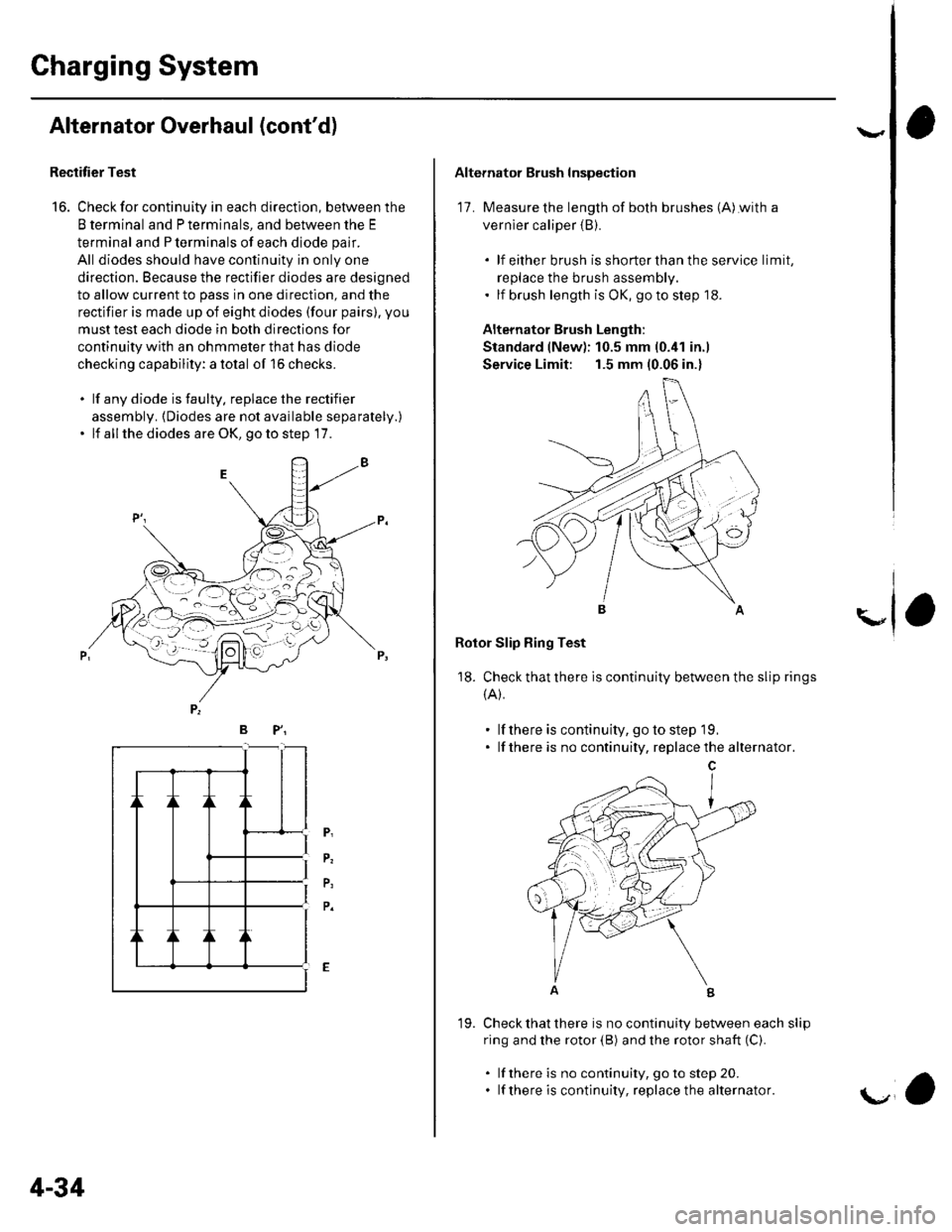
Charging System
Alternator Overhaul (cont'd)
Rectitier Test
16. Check for continuity in each direction, between the
B terminal and P terminals, and between the E
terminal and P terminals of each diode pair.
All diodes should have continuity in only one
direction. Because the rectifier diodes are designed
to allow current to pass in one direction, and the
rectifier is made up of eight diodes (four pairs). you
musttest each diode in both directions for
continuity with an ohmmeter that has diode
checking capability: a total of 16 checks.
. lf any diode is faulty. replace the rectifier
assembly. {Diodes are not available separately.)' lf all the diodes are OK, go to step 17.
/--:',t- -L . --- -o \-- l'-=
BP"
P,
P.
P,
P.
4-34
19.
'a
Alternator Brush Inspection
17. Measure the length of both brushes (A)with a
vernier caliper {B).
. lf either brush isshorterthanthe service limit,
replace the brush assembly.. lf brush length is OK, go to step '18.
Alternator Brush Length:
Standard (New): 10.5 mm (0.41 in.)
Service Limit: 1.5 mm (0.06 in.)
Rotor Slip Bing Test
18. Check that there is continuity between the slip rings
{A).
. lf there is continuity, go to step 19.. lf there is no continuity, replacethe alternator.
Check that there is no continuity between each slip
ring and the rotor (B) and the rotor shaft (C).
. lf there is no continuity, goto step 20.. lf there is continuity, replace the alternator.
\"
Page 75 of 1139
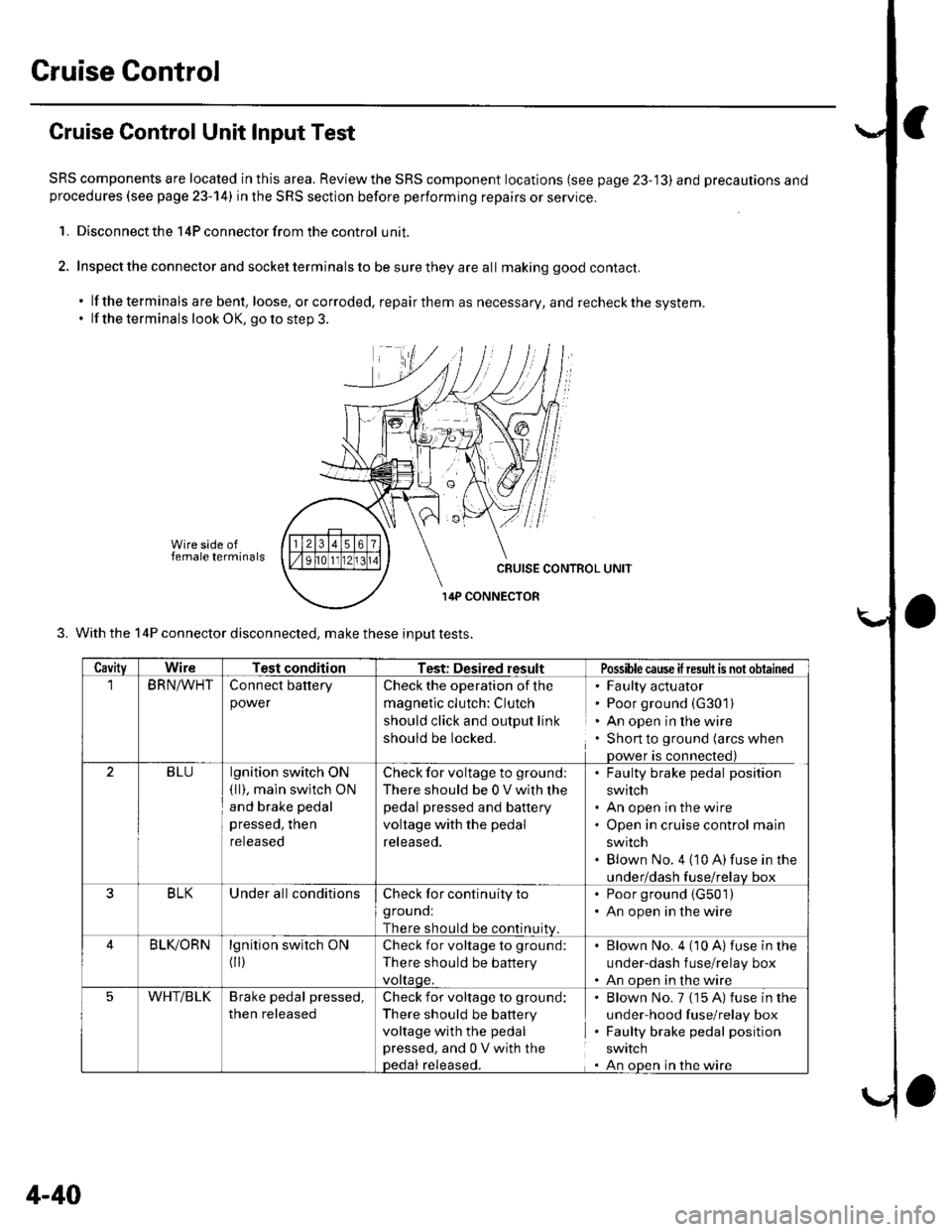
Cruise Gontrol
Cruise Control Unit Input Test
SRS components are located in this area. Reviewthe SRS component locations (see page 23-'13) and precautions andprocedures (see page 23-14) in the SRS section before performing repairs or service.
1. Disconnect the 14P connector from the control unit.
2. Inspect the connector and socket terminals to be sure they are all making good contact.
. lf the terminals are bent, loose, orcorroded, repairthem as necessary, and recheckthe system.. lf the terminals look OK, go to step 3.
Wire side offemale terminals
3. With the 14P connector disconnected, make these inDut tests.
CavityWireTest conditionTest: Desired resultPossiblecause ifresuh is not obtained
BRN/WHTConnect battery
power
Check the operation of the
magnetic clutch: Clutch
should click and output link
should be locked.
' Faulty actuator. Poor ground (G301)
. An open in the wire. Shon to ground (arcs when
Dower is connected)
2BLUlgnition switch ON(ll), main swltch ON
and brake pedal
pressed, then
reteaseo
Check for voltage to ground;
There should be 0 V with lhe
pedal pressed and battery
voltage with the pedal
released.
. Faulty brake pedal position
switch. An open in the wire. Open in cruise control main
swrtcn. Blown No. 4 (10 A)fuse in the
under/dash fuse/relav box
3BLKUnder all conditionsCheck for continuity to
grouno:
There should be continuitv
. Poor ground (G501)
. An open in the wire
BLIVORNlgnition switch ON
flr)
Check for voltage to ground:
There should be battery
vottaqe.
Blown No. 4 (10 A)fuse in the
under-dash f use/relay box
An oDen in the wire
5WHT/BLKBrake pedal pressed,
then released
Check for voltage to ground:
There should be battery
voltage with the pedal
pressed, and 0 V with thepedal released.
Blown No. 7 {15 A) fuse in the
under-hood fuse/relay box
Faulty brake pedal position
SWIICN
An oDen in the wire
4-40
Page 123 of 1139
Cylinder Head
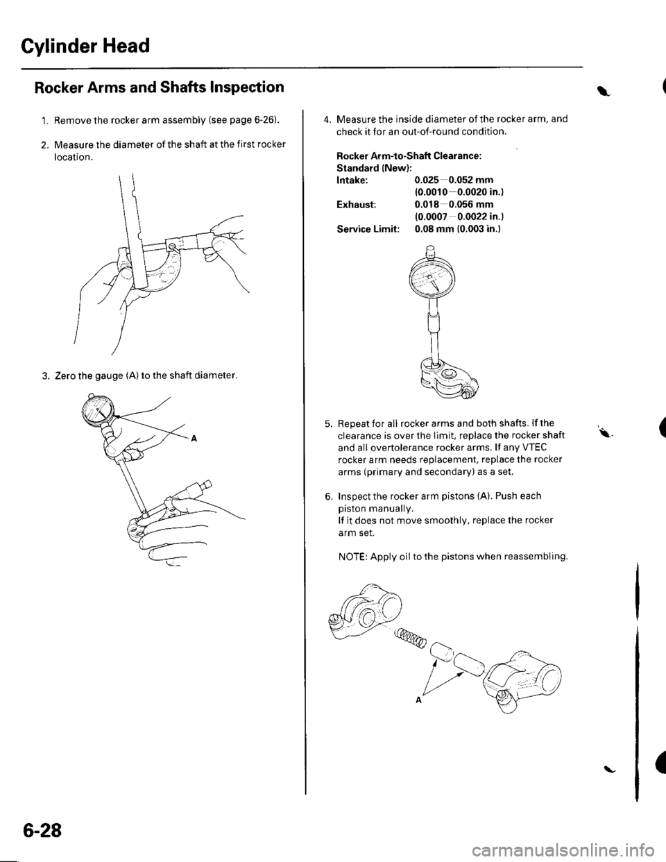
1.
2.
Rocker Arms and Shafts Inspection
Remove the rocker arm assembly (see page 6-26).
Measure the diameter of the shaft at the first rocker
location.
3. Zero the gauge (A) to the shaft diameter.
6-28
\
4. Measure the inside diameter ofthe rocker arm, and
check it for an out-of-round condition.
Rocker Arm-to-Shaflt Clearance:
Standard lNew):
lntake: 0.025 0.052 mm(0.0010 0.0020 in.)
Exhaust: 0.018 0.056 mm
(0.0007 0.0022 in.)
Service Limit: 0.08 mm (0.003 in.)
5. Repeat for all rockerarms and both shafts. lfthe
clearance is over the Ilmit. replace the rocker shaft
and all overtolerance rocker arms. lf any VTEC
rocker arm needs replacement, replace the rocker
arms (primary and secondary) as a set.
6. Inspect the rocker arm pistons {A}. Push each
piston manually.
lf it does not move smoothly, replace the rocker
arm set.
NOTE: Apply oil to the pistons when reassembling.
,,,@@
(\.
(
Page 124 of 1139
Gamshaft Inspection
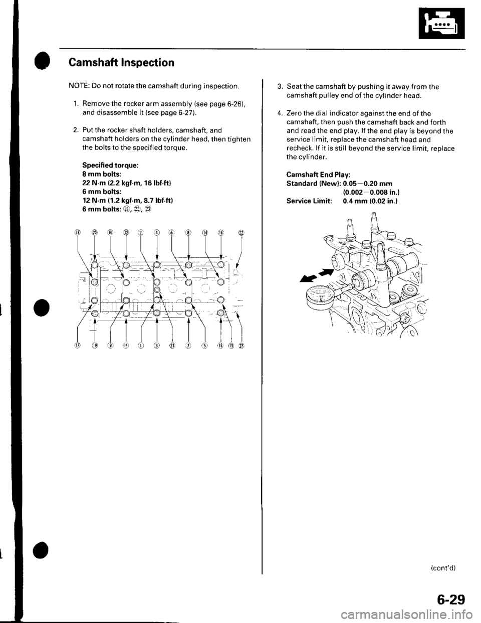
NOTE: Do not rotate the camshaft during inspection.
1. Remove the rocker arm assembly (see page 6-26).
and disassemble it (see page 6-27).
2. Put the rocker shaft holders, camshaft, and
camshaft holders on the cylinder head, then tighten
the bolts to the specified torque.
Specified torque:
I mm bolis:
22 N.m {2.2 kgt m, 16lbf.ft}
6 mm bolts:
12 N.m {1.2 kgf.m,8.7 tbf.ftl
6 mm bolts: @, €0, @
I
I
3. Seat the camshaft by pushing it away from the
camshaft pulley end ofthe cylinder head.
4. Zero the dial indicator against the end of the
camshaft, then push the camshaft back and forth
and read the end play. lf the end play is beyond the
service limit, replace the camshaft head and
recheck. lf it is still beyond the service limit, replace
the cylinder.
Camshaft End Play:
Standard {New}: 0.05 0.20 mm(0.002 0.008 in.l
Service Limit: 0.4 mm (0.02 in.)
(cont'd)
6-29
Page 125 of 1139
Cylinder Head
Camshaft Inspection (cont'dl
1.
9.
Unscrew the camshaft holder bolts two turns at a
time, in a crisscross pattern. Then remove the
camshaft holders from the cylinder head.
Lift the camshafts out of the cylinder head, wipe
them clean. then inspect the lift ramps. Replace the
camshaft if any lobes are pitted, scored, or
excessively worn,
Clean the camshaft journal surfaces in the cylinder
head, then set the camshafts back in place. Place a
plastigage strip across each journal.
Install the camshaft holders, then tighten the bolts
to the specified torque as shown in step 2.
Remove the camshaft holders. Measure the widest
portion of plastigage on each journal.
. lf the camshaft-to-holder clearance is within
limits, go to step 1 1.. lf the camshaft-to-holder clearance is beyond the
service limit and the camshaft has been replaced,
replace the cylinder head.. lf the camshaft-to-holder clearance is beyond the
service limit and the camshaft has not been
replaced, go to step 10.
Camshaft-to-Holder Oil Clearance:
Standard (New):
No. 1 Journal:
No.2,3,4,5 Journals:
Service Limit:
0.030 0.069 mm
{0.001 0.003 in-)
0.060*0.099 mm
{0.002 0.004 in.)
0.15 mm {0.006 in.)
6-30
\-
{\
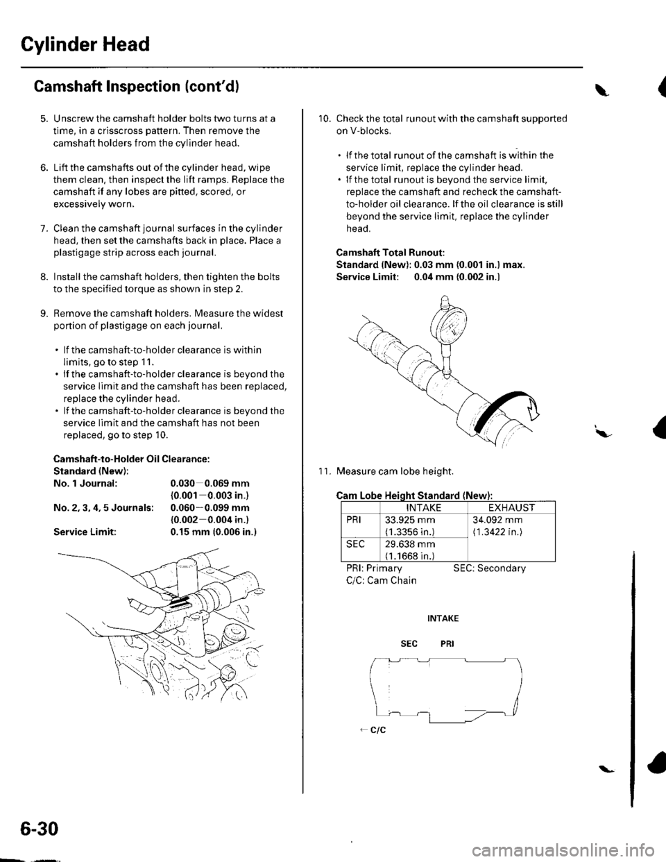
10. Check the total runout with the camshaft supported
on V-blocks,
.lfthetotal runout of the camshaft is within the
service limit, replace the cylinder head.. lf the total runout is beyond the service limit,
replace the camshaft and recheck the camshaft-
to-holder oil clearance. lf the oil clearance is still
beyond the service limit, replace the cylinder
neao.
Camshaft Total Runout:
Standard (New): 0.03 mm (0.001 in.) max.
Service Limit: 0.04 mm {0.002 in.)
11. Measure cam lobe height.
Cam
PRI: Primary
C/C: Cam Chain
SEC: Secondary
I\,
Lobe Heioht Standard (New
INTAKEEXHAUST
PRI33.925 mm(1.3356 in.)
34.092 mm
\1 .3422 in.l
SEC29.638 mm(1.1668 in.)
Page 127 of 1139
Gylinder Head
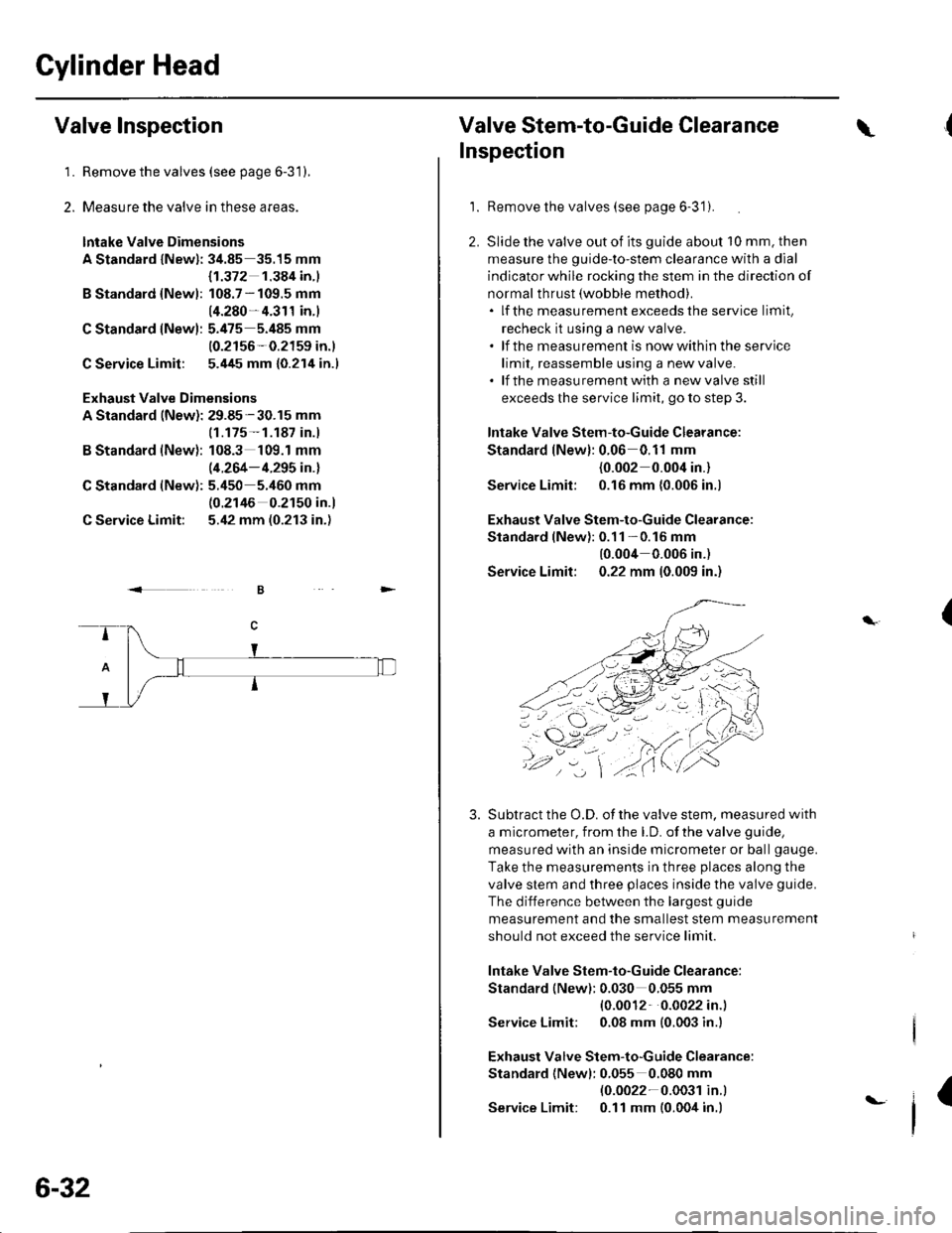
Valve Inspection
1.Remove the valves (see page 6-31),
Measure the valve in these areas.
lntake Valve Dimensions
A Standard lNewl: 34.85 35.15 mm
B Standard {Newl:
C Standard lNew):
C Service Limit:
B Standard (New):
C Standard (New):
C Service Limit:
Exhaust Valve Dimensions
A Standard (New): 29.85-30.15 mm
{1.372 1.384 in.l
108.7 - 109.5 mm
14.280- 4.311 in.)
5.475 5.485 mm
10.2156-0.2159 in.)
5.445 mm {0.214 in.l
(1.175- 1.187 in.)
108.3 109.1 mm
(4.264- 4.295 in.l
5.450 5.460 mm(0.2146 0.2150 in.)
5.42 mm (0.213 in.)
2.
.<
6-32
t-
Valve Stem-to-Guide Clearance\
Inspection
1.Remove the valves (see page 6-3'1).
Slide the valve out of its guide about 10 mm. then
measure the guide-to-stem clearance with a dial
indicator while rocking the stem in the direction of
normal thrust (wobble method).. lf the measurement exceedsthe service limit,
recheck it using a new valve.. lf the measurement is nowwithin the service
limit, reassemble using a new valve.. lf the measurementwith a newvalve still
exceeds the service limit, go to step 3.
lntake Valve Stem-to-Guide Clearance:
Standard lNew): 0.06 0.11 mm
{0.002 0.004 in.}
Service Limil: 0.16 mm {0.006 in.)
Exhaust Valve Stem-to-Guide Clearance:
Standard lNewl:0.11 -0.16 mm
10.004 0.006 in.)
Service Limit: 0.22 mm 10.009 in.)
Subtract the O.D. of the valve stem. measured with
a micrometer, from the LD. of the valve guide,
measured with an inside micrometer or ball gauge.
Take the measurements in three places along the
valve stem and three places inside the valve guide.
The difference between the largest guide
measurement and the smallest stem measurement
should not exceed the service limit
lntake Valve Stem-to-Guide Clearance:
Standard (New): 0.030 0.055 mm
{0.0012 0.0022 in.)
Service Limit; 0.08 mm (0.003 in.l
Exhaust Valve Stem-to-Guide Clearance:
Standard {Newl: 0.055 0.080 mm(0.0022-0.003r in.l
Service Limit: 0.11 mm (0.004 in.)
(
3.
4,.
I
Page 130 of 1139
Valve Seat Reconditioning
1. Inspect valve stem-to-guide clearance (see page 6-
32). lf the valve guides are worn, replace them (see
page 6-33) before cutting the valve seats.
2. Renew the valve seats in the cylinder head using a
valve seat cutter.
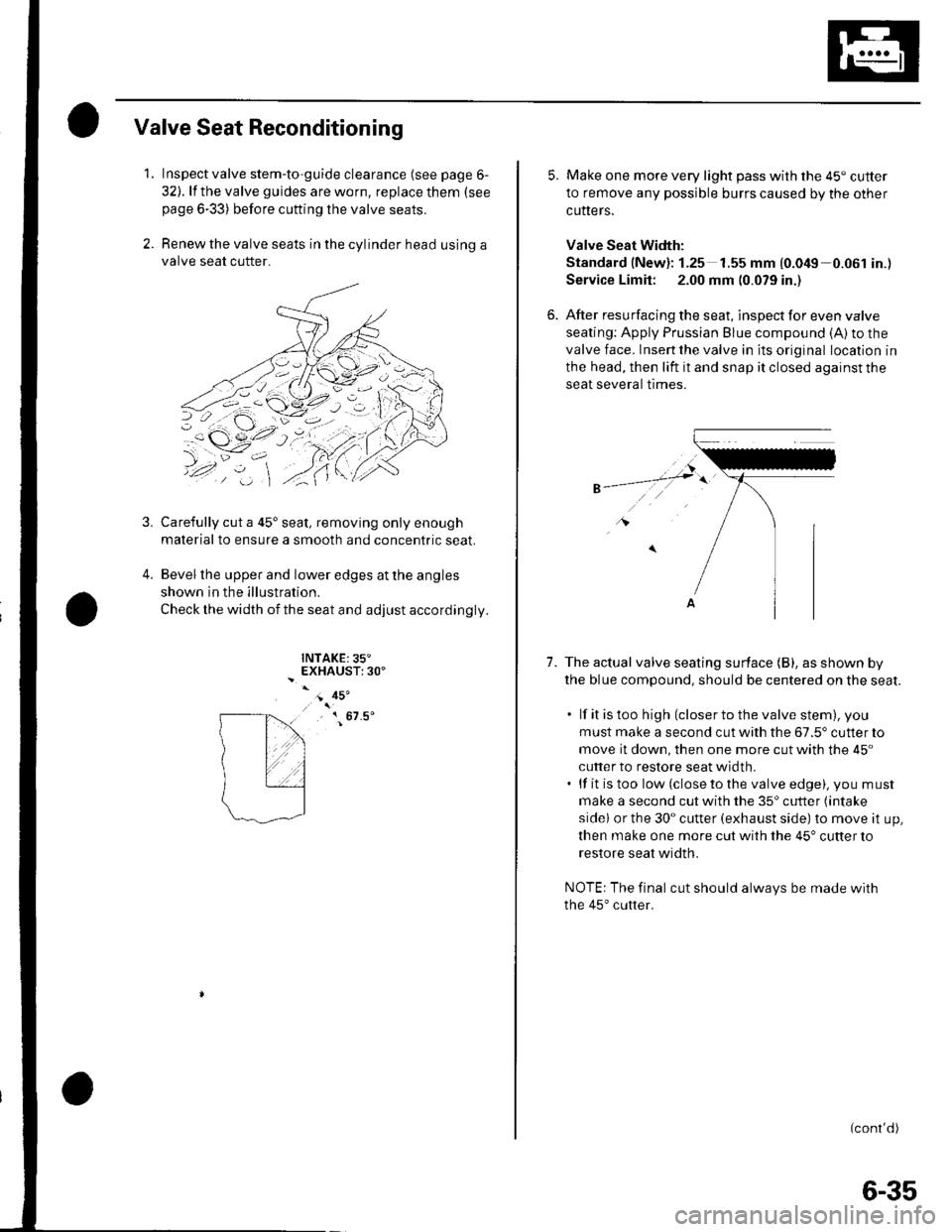
Carefully cut a 45'seat, removing only enough
material to ensure a smooth and concentric seat.
Bevel the upper and lower edges at the angles
shown in the illustration.
Check the width of the seat and adjust accordingly.
INTAKE:35"EXHAUST:30'
3,
4.
- 45'
, { 67.5'
5. Make one more very light pass with the 45" cutter
to remove any possible burrs caused by the other
cutters.
Valve Seat Width:
Standard (New): 1.25 1.55 mm {0.049 0.061 in.)
Service Limit: 2.00 mm (0.079 in.)
6. After resurfacing the seat, inspect for even valve
seating: Apply Prussian Blue compound (A) to the
valve face. Insert the valve in its original location in
the head, then lift it and snap it closed against the
seat several trmes.
1.The actual valve seating surface (B), as shown by
the blue compound, should be centered on the seat.
. lf it is too high (closer to the valve stem), you
must make a second cut with the 67.5' cutter to
move it down, then one more cut with the 45"
cutter to restore seat width.. lf it is too low (close to the valve edge), you must
make a second cut with the 35'cutter (intake
sidel or the 30" cutter (exhaust side) to move it up,
then make one more cut with the 45" cutter to
restore seat width.
NOTE: The final cut should always be made with
the 45'cutter.
(cont'd)
6-35