service HONDA CIVIC 2002 7.G Service Manual
[x] Cancel search | Manufacturer: HONDA, Model Year: 2002, Model line: CIVIC, Model: HONDA CIVIC 2002 7.GPages: 1139, PDF Size: 28.19 MB
Page 176 of 1139
Engine Lubrication
Oil Pump Overhaul {cont'dl
Oil Pump Inspection
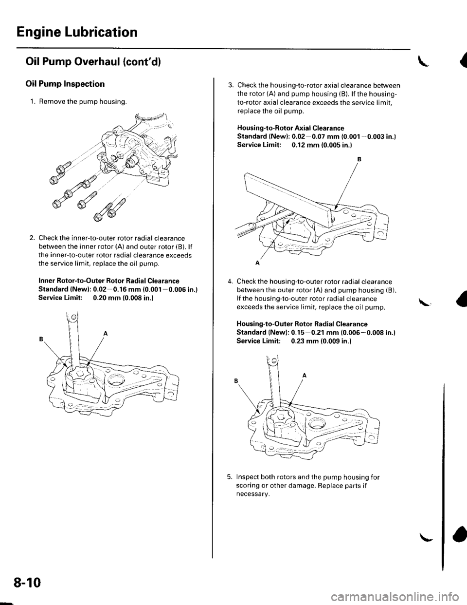
1. Remove the pump housing.
Check the inner-to-outer rotor radial clearance
between the inner rotor (A) and outer rotor {B). lf
the inner-to-outer rotor radial clearance exceeds
the service limit, replace the oil pump.
Inner Rotor-to-Outer Botor Radial Clearance
Standard {New): 0.02 0.16 mm (0.001 -0.006 in.)
Service Limit: 0.20 mm (0.008 in.,
1'[1e-\1.-,-2
1 'a - :.: ,-'r'
8-10
\-
{
4.
3. Check th e h ousing-to-roto r axia I clearance between
the rotor (A) and pump housing (B). lf the housing-
to-rotor axial clearance exceeds the service limit.
replace the oil pump.
Housing"to-Rotor Axial Clearance
Standard (New): 0.02 0.07 mm (0.001 -0.003 in.l
Service Limit: 0.12 mm (0.005 in.l
Check the housing-to-outer rotor radial clearance
between the outer rotor (A) and pump housing (B).
lf the housing-to-outer rotor radial clearance
exceeds the service limit, replace the oil pump.
Housing-to-Outer Rotor Radial Clearance
Standard lNewl: 0.15 0.21 mm (0.006-0.008 in.l
Service Limit; 0.23 mm (0.009 in.)
Inspect both rotors and the pump housing for
scoring or other damage. Replace parts if
necessary.
\,
Page 177 of 1139
1.
Balancer Shaft Inspection
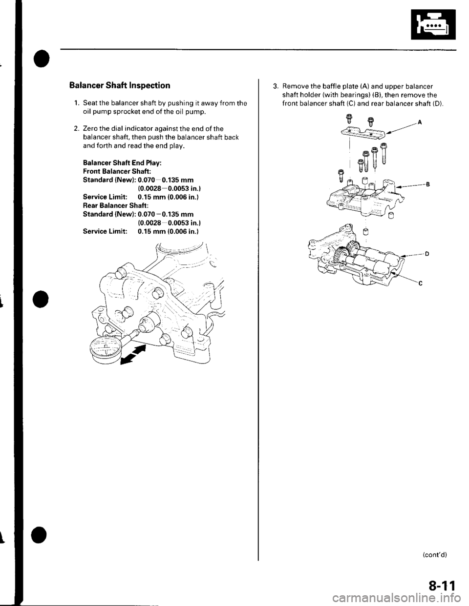
Seat the balancer shaft by pushing it away from the
oil pump sprocket end ofthe oil pump.
Zero the dial indicator against the end of the
balancer shaft, then push the balancer shaft back
and forth and read the end olav.
Balancer Shaft End Play:
Fronl Balancer Shaft:
Standard {Newl: 0.070 0.135 mm
{0.0028 0.0053 in.}
Service Limit: 0.15 mm (0.006 in.)
Rear Balancer Shaft:
Standard {New): 0.070-0.135 mm(0.0028 0.0053 in.l
Service Limit: 0.15 mm (0.006 in.)
2.
3. Remove the baffle plate (A) and upper balancer
shaft holder {with bearings) (B), then remove the
front balancer shaft (C) and rear balancer shaft (D).
9H.A''/.r L=] j/
R
Rfl|]
3I] UUr Be
+-
(cont'd)
8-11
Page 178 of 1139
Engine Lubrication
Oil Pump Overhaul (cont'dl
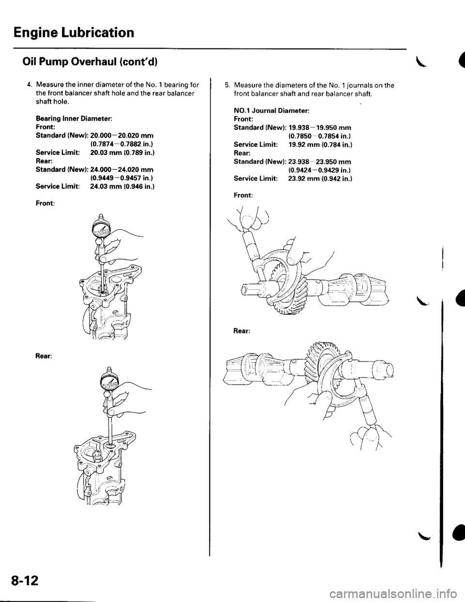
4. Measure the inner diameter of the No. 1 bearing for
the front balancer shaft hole and the rear balancer
shaft hole.
Bearing Inner Diameier:
Front:
Standard (New): 20.000-20.020 mm(0.7874 0.7882 in.)
Service Limit; 20.03 mm (0.789 in.)
Rear:
Standard (New): 24.000-24.020 mm
10.9/t49-0.9457 in.)
Service Limit: 24.03 mm (0.946 in.)
Front:
Rear:
8-12
\
(
5.Measure the diameters of the No. 1 journals on the
front balancer shaft and rear balancer shaft.
NO.1 Journal Diameter:
Front:
Standard lNew): 19.938 19.950 mm(0.7850 0.7854 in.)
Service Limit: 19.92 mm {0.784 in.)
Rear:
Standard lNewl: 23.938 23.950 mm
{0.9424-0.9/129 in.)
Service Limit: 23.92 mm (0.942 in.)
Front:
a
Page 179 of 1139
8.
9.
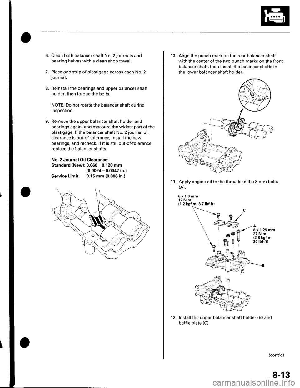
6. Clean both balancer shaft No. 2 journals and
bearing halves with a clean shop towel.
7. Place one strip of plastigage across each No.2journal.
Reinstall the bearings and upper balancer shaft
holder, then torque the bolts.
NOTE; Do not rotate the balancer shaft durinq
insDection.
Remove the uooer balancer shaft holder and
bearings again, and measure the widest part of the
plastigage. lf the balancer shaft No. 2 journal oil
clearance is out-of-tolerance. install the new
bearings, and recheck. lf it is still out-of-tolerance,
replace the balancer shafts.
No. 2 Journal Oil Clearance:
Standard lNewl; 0.060 0.120 mm
Service Limit:
(0.0024 0.0047 in.l
0.15 mm {0.006 in.)
10. Align the punch mark on the rear balancer shaft
with the center of the two punch marks on the front
balancer shaft, then install'the balancer shafts in
the lower balancer shaft holder
Apply engine oil to the threads of the 8 mm bolts(A).
6x1.0mm'12 N.m(1.2 kgt.m, 8.7 lbt ft)
11.
Installthe upper balancer shaft holder (B) and
bafile plate (C).
(cont'd)
12.
8-13
Page 214 of 1139
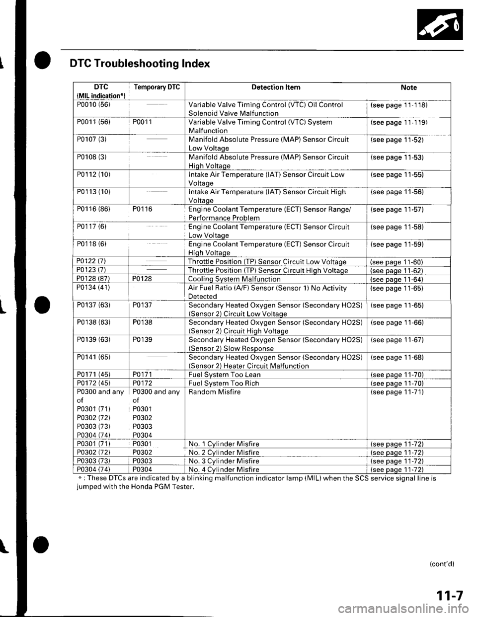
DTC Troubleshooting Index
";These DTCs are indicated by a blinking malfunction indicator lamp (MlL)when the SCS service signal line isjumped with the Honda PGM Tester.
{cont'd)
11-7
DTC
{MlL indication*)
Temporary DTCDetection ltemNote
P0010 (56)Variable Valve Timing Control {VTC) Oil Control
Solenoid Valve Malfunction
{see page 1 1'1 18)
P0011 (56)P001 1Variable Valve Timing Control (WC) System
Malfunction
(see page 11- 1 19)
P0107 (3)Manifold Absolute Pressure (MAP) Sensor Circuit
Low Voltaqe
(see page 1'l-521
P0108 (3)Manifold Absolute Pressure (MAP) Sensor Circuit
Hiqh Voltaqe
(see page 11-53)
P0112 (10)Intake Air Temperature (lAT) Sensor Circuit Low
Voltaoe
(see page 11-55)
P01r3 (10)Intake Air Temperature (lAT) Sensor Circuit High
Voltaoe
(see page '11-56)
P0116 {86) P0116Englne Coolant Temperature (ECT) Sensor Range/
Performance Problem
{see page 11-57)
P0117 {6)Engine Coolant Temperature (ECT) Sensor Circuit
Low Voltaqe
(see page 11-58)
P0118 {6)Engine Coolant Temperature (ECT) Sensor Circuit
Hiqh Voltaqe
{see page 11-59)
P0122 t7\Throttle Position (TP) Sensor Circuit Low Voltaqe(see Daqe 11-60)P0123 {7)Throttle Posltion (TP) Sensor Circuit Hiqh Voltaoe(see paqe 11-62)
P0128 (87)P0128Coolinq SVStem Malfunction(see Daqe 11-64)
P0134 (41)Air Fuel Ratio (Ay'F) Sensor (Sensor 1) No Activity
Detected
(see page 11-65)
P0137 (63)P0137Secondary Heated Oxygen Sensor (Secondary HO2S)(Sensor 2) Circuit Low Voltaqe
(see page 11-65)
P0138 (63)P0138Secondary Heated Oxygen Sensor (Secondary HO2S)(Sensor 2) Circuit Hiqh Voltaqe
(see page 11-66)
P0139 (63)P0139Secondary Heated Oxygen Sensor (Secondary H02S)(Sensor 2) Slow ResDonse
(see page 11-67)
P0141 (65)Secondary Heated Oxygen Sensor (Secondary H02S)(Sensor 2) Heater Circuit Malfunction
(see page 11-68)
P0171 (45)PO\11Fuel Svstem Too Lean(see paqe 11-70)
PO112 l'45)PO\l2Fuel System Too Rich(see oaoe 11-70)
P0300 and any P0300 and any
of of
P0301 (71) P0301
PO302 (721 P0302
P0303 (73) P0303
P0304 (74) P0304
Random Misfire(see page 11-71)
P0301 (7'1) P0301No. 1 Cylnder Misfire{see page 11-72)
P0302 (721 P0302No. 2 Cvlnder Misfire{see paqe 1 1-72)
P0303 (73)P0303No. 3 Cvlnder Misfire(see oaqe 11-72)
P0304 {74)P0304No. 4 Cvlnder Misfire{see Daqe 1 1-72)
Page 216 of 1139
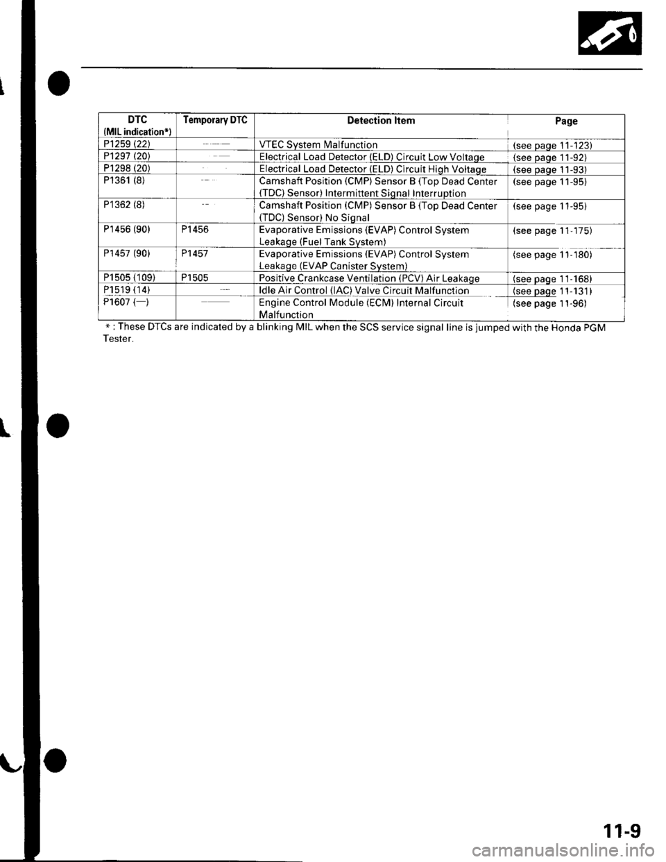
DTC
{MlL indication*l
Temporary DTCDetection ltemPage
P1259 t22JVTEC System l\4alfunction(see Daqe 11-123)P1291 t20\Electrical Load Detector (ELD) Circuit Low Voltaqe(see Daqe l1-92)P1298 (20)Electrical Load Detector (ELD) Circuit Hiqh Voltaqe(see oaoe 11-93)P1361 (8)Camshaft Position (CMP) Sensor B (Top Dead Center(TDC) Sensor) Intermittent Sional InterruDtion
(see page 11-95)
P1362 (8)Camshaft Position (CMP) Sensor B (Top Dead Center(TDC) Sensor) No Siqnal
(see page 11-95)
P'r456 (90)P1456Evaporative Emissions (EVAP) Control System
Leakaqe (Fuel Tank Svstem)
(see page 11-175)
P14s7 (90)P1457Evaporative Emissions (EVAP) Control System
Leakaqe (EVAP Canister Svstem)
(see page 1'l-180)
P1505 (109)P1505Positive Crankcase Ventilation (PCV) Air Leakaqe(see oaqe 11-1681
P1519 (14)ldle Air Control (lAC) Valve Circuit Malfunction{see paqe 11-131)P1607 ( )Engine Control Module (ECM) Internal Circuit
Malfunction
(see page 1 1-96)
" : These DTCS are indicated by a blinking MIL when the SCS service signal line is jumped with the Honda PGM
Tester.
11-9
Page 221 of 1139
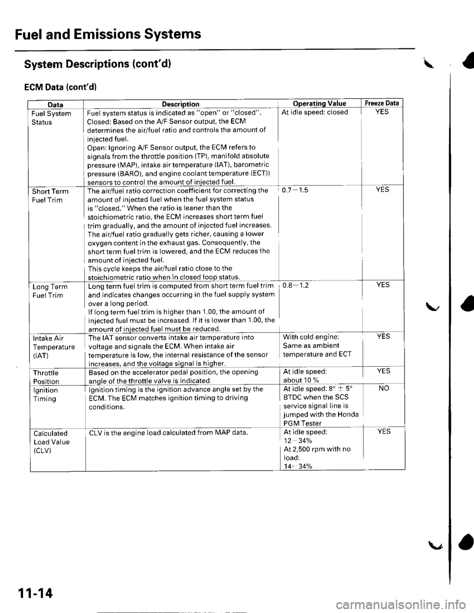
Fuel and Emissions Systems
System Descriptions (cont'd)
ECM Data (cont'd)
w
DataDescriptionOpera'ting ValueFreeze Data
Fuel System
Status
Fuel system status is indicated as "open" or "closed".
Closed: Based on the A,/F Sensor output, the ECM
determines the airlfuel ratio and controls the amount of
injected fuel.
Open: lgnoring Ay'F Sensor output, the ECM refers to
signals from the throttle position {TP), manifold absolute
pressure (MAP), intake air temperature (lAT), barometric
pressure (BARO), and engine coolant temperature (ECT))
sensors to control the amount of iniected fuel.
At idle speed: closedYES
Short Term
FuelTrim
The airlfuel ratio correction coefficient for correcting the
amount of injected fuel when the fuel system status
is "closed." When the ratio is leaner than the
sloichiometric ratio, the ECM increases short term fuel
trim gradually, and the amount of iniected fuel increases.
The airlfuel ratio gradually gets richer, causing a lower
oxygen content in the exhaust gas. Consequently, the
short term fuel trim is lowered, and the ECM reduces the
amount of injected fuel.
This cvcle keeps the airlfuel ratio close to the
stoichiometric ratio when in closed loop status.
o.7 1.5YES
Long Term
Fuel Trim
Long term fuel trim is computed from short term fuel trim
and indicates changes occurring in the fuel supply system
over a long period.
lf long term fuel trlm is higher than 1.00, the amounl of
injected fuel must be increased. lf it is lower than 1.00, the
amount of injected fuel must be reduced.
0.8 1.2YES
Intake Air
Temperature
{IAT)
The IAT sensor converts intake air temperature into
voltage and signals the ECM. When intake air
temperature is low, the internal resistance ofthe sensor
increases, and the voltage signal is higher.
With cold engine:
Same as ambient
temperature and ECT
YES
Throttle
Position
Based on the accelerator pedal position, the opening
anole of the throttle valve is indicated.
At idle speed:
about 10 %
YES
lgnition
Timing
lgnition timing is the ignition advance angle set by the
ECM. The ECM matches ignition timing to driving
conditions.
At idle speed: 8" t 5"
|' tuL wnen rne >L)
service signal line is
jumped with the Honda
PGM Tester
NO
Calculated
Load Value
(cLV)
cLV is the enoine load calculated from IMAP data.At idle speed:
12 34%
At 2.500 rpm with no
toao:'t4- 34%
YES
11-14
\.,
ra
Page 230 of 1139
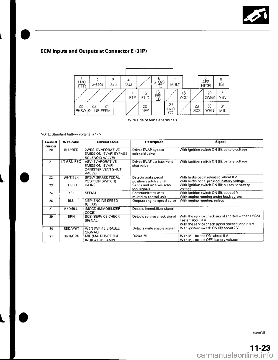
ECM Inputs and Outputs at Connector E (31P)
ltMoFPR
2$.c2s
i6SFIO2SHTC
1
IV RLY
IAFSHTCR
9tGl
14FTP15ELD
16EPSLD
t8202,4/BS21VSV
22BKSW23K LINE24SEFMJ26NEP
21lvoCD
29scs30WEN31MIL
Wire side of female terminals
NOTE: Standard battery voltage is 12 V.
TerminalWire colorTerminalnameDescriptionSignal
20BLU/RED2WBS (EVAPORATIVEEMISSION (EVAP)BYPASSSOLENOID VALVE)
Drives EVAP bypass With ignition switch ON (ll): baftery voltagesolenoid valve
21LT GRN/REDVSV (EVAPORATIVE
EI\4ISSION iEVAP)CANISTEB VENT SHUTVALVE)
Drives EVAP canister ventshut valveWith ignilion switch ON (ll): battery voltage
22WHT/BLKBKSW lBRAKE PEDALPOSITION SWITCH)Detects brake pedaloosition switch sionalWith brake pedal released: about 0 VWith hrake nedal nresse.l: batterv voltaoe23LT BLUK-LIN ESends and receives scanWith ignition switch ON (li)r pulses or battery
YELSEFMJCommunicates withmrltinleY eontrol unitWith ignition switch ON (ll): about 5 VWith enoine runnino under load: DUlses26BLUNEP (ENGINE SPEEDPULSE)Outputs engine speed pulseWith engine running: pulses
21RED/BLU \40CD fl\4MOBTLTZERCODE)Detects imrnobilizer signal
29BRNSCS (SERVICE CHECKSIGNAL)Oetects service check signalWith the service check signal shorted with the PGMTester: about 0 VWiih rhe service check sional ooened: about 5 V
30RED,A/VHTWEN (WRITE ENABLESIGNALiDetects write enable signal With ignition switch ON (ll): about 0 V
GRN/ORNMIL (MALFUNCTION
INDICATOR LAMP)Drives N4lLWith MIL turned ON: about 0 VWith MIL turned OFF: batterv voltaqe
(cont'd)
11-23
Page 406 of 1139
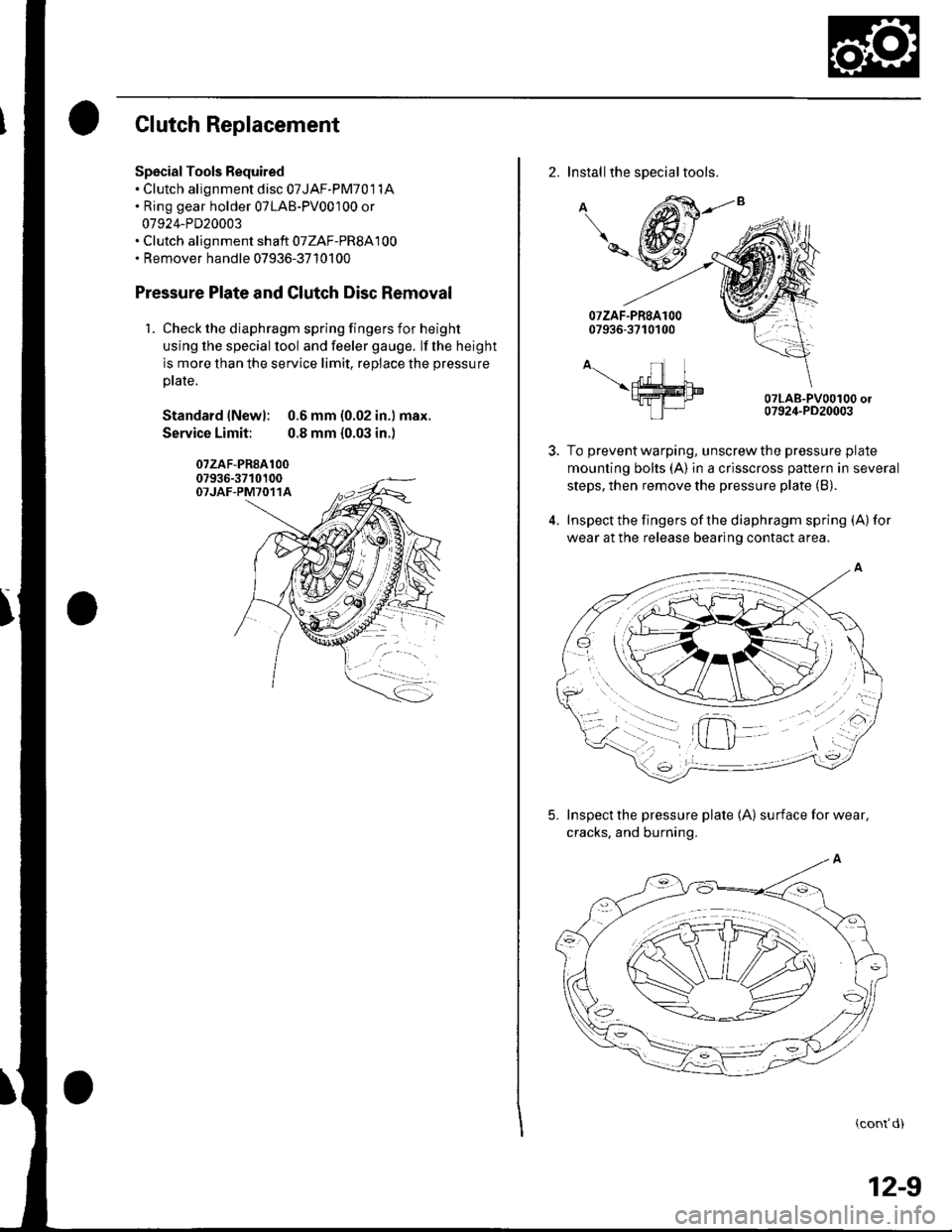
Clutch Replacement
Spscial Tools Required. Clutch alignment disc 07JAF-PM701 1A. Ring gear holder 07LAB-PV00100 or
07924-PD20003. Clutch alignment shaft 07ZAF-PR8A100. Remover handle 07936-3710100
Pressure Plate and Glutch Disc Removal
1. Check the diaphragm spring fingers for height
using lhe special lool and feeler gauge. lf the height
is more than the service limit, replace the pressure
ptate.
Standard lNewl: 0.6 mm (0.02 in.) max.
Service Limit: 0.8 mm {0.03 in.)
07zAF-PR8A10007936-3710100OTJAF-PM7O11A
2. Installthe special tools.
A
\-
A-.- nl I\ffim9fra-I tP|-
07LAB-PV00100 or07924-PD20003
To prevent warping, unscrew the pressure plate
mounting bolts (A) in a crisscross pattern in several
steps, then remove the pressure plate (B).
Inspect the fingers of the diaphragm spring (A) for
wear at the release bearing contact area.
5. Inspect the pressure plate 1A) surfaceforwear,
cracks. and burning.
(cont'd)
12-9
Page 407 of 1139
Clutch
Clutch Replacement (cont'd)
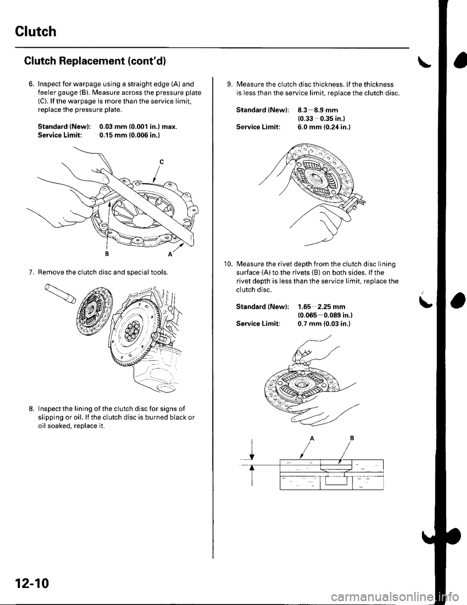
6. Inspecl for warpage using a straight edge (A) and
feeler gauge (B). l\4easure across the pressure plate
(C). lf the warpage is more than the service limit,
replace the pressure plate.
Standard {New): 0.03 mm (0.001 in.) max.
Service Limit: 0.15 mm (0.006 in.)
7. Remove the clutch disc and sDecialtools.
Inspectthe lining ofthe clutch disc for signs of
slipping or oil. lf the clutch disc is burned black or
oil soaked. reolace it.
1d
12-10
9. lvleasu re th e clutch d isc th ickness. lfthethickness
is less than the service limit, replace the clutch disc.
Standard lNew): 8.3 8.9 mm(0.33 0.35 in.)
Service Limit: 6.0 mm {0.24 in.)
Measure the rivet depth from the clutch disc lining
surface (A) to the rivets (B) on both sides. lf the
rivet depth is less than the service limit, replace the
clutch disc.
Standard (New): 1.65 2.25 mm(0.065 0.089 in.)
Service Limit: 0.7 mm (0.03 in.)
10.
L