ECU HONDA CIVIC 2002 7.G Owner's Guide
[x] Cancel search | Manufacturer: HONDA, Model Year: 2002, Model line: CIVIC, Model: HONDA CIVIC 2002 7.GPages: 1139, PDF Size: 28.19 MB
Page 358 of 1139
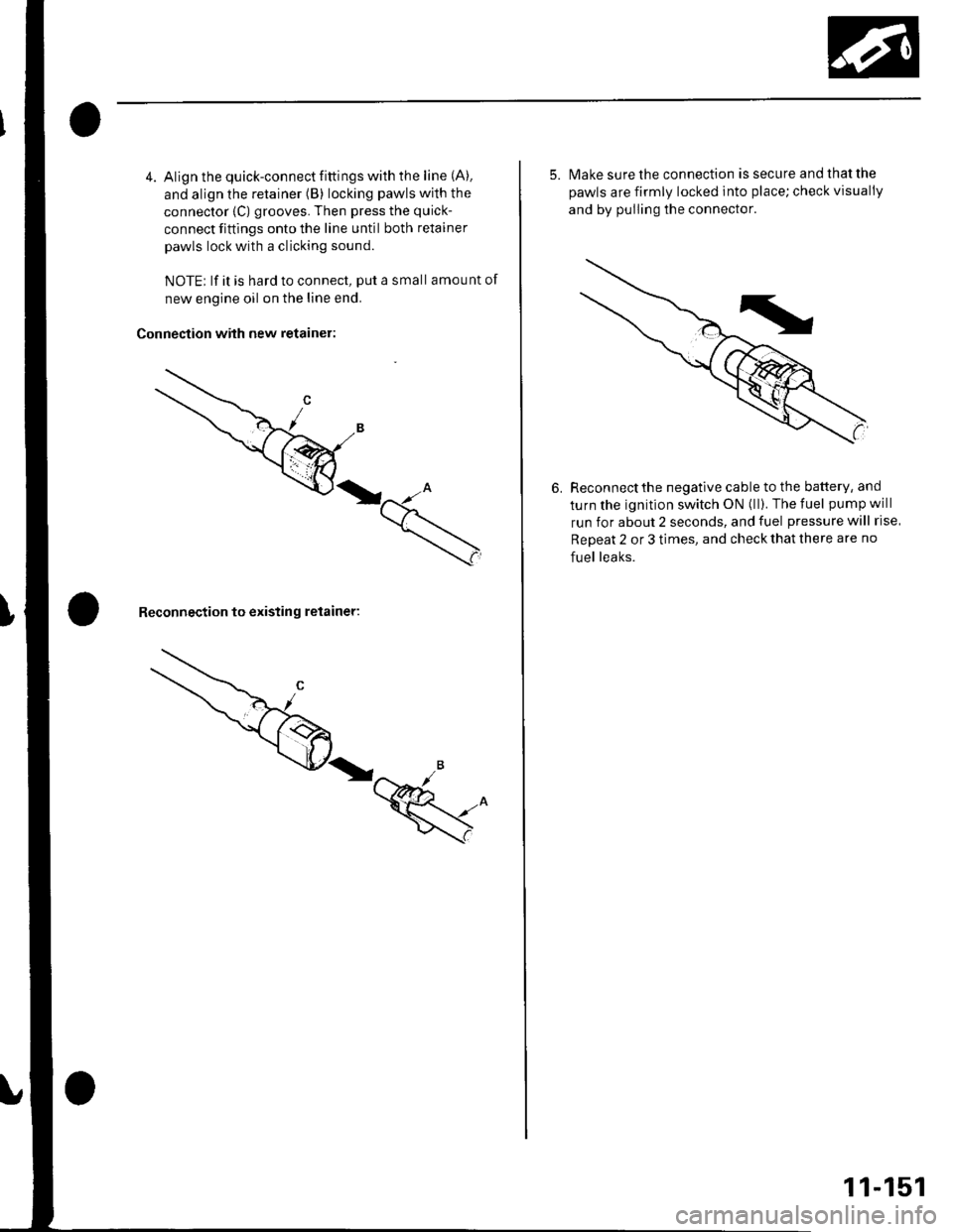
4. Align the quick-connect fittings with the line (A).
and align the retainer (B) locking pawls with the
connector {C) grooves. Then press the quick-
connect fittings onto the line until both retainer
pawls lock with a clicking sound.
NOTE; lf it is hard to connect, put a small amount of
new engine oil on the line end.
Connection with new retainer:
Reconnection to existing retainer:
5. lvlake sure the connection is secure and that the
pawls are firmly locked into place; check visually
and by pulling the connector.
6. Reconnectthe negative cable to the battery, and
turn the ignition switch ON (ll). The fuel pump will
run for about 2 seconds, and fuel pressure will rise
Repeat 2 or 3 times, and check that there are no
fuel leaks.
11-151
Page 359 of 1139
Fuel Supply System
{Fuel Pressure Regulator
Replacement
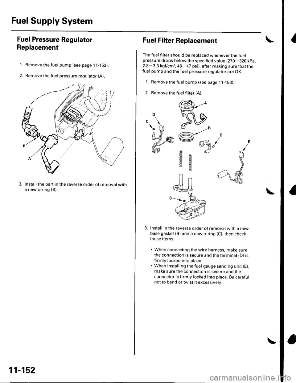
Remove the fuel pump (see page 1 1-153).
Remove the fuel pressure regulator (A).
Installthe part in the reverse order of removal witha new o-ring (B).
1.
2.
11-152
Fuel Filter Replacement
The fuel filter should be replaced whenever the fuelpressure drops belowthe specified value {270 320 kpa,2.8 3.3 kgf lcm', 40 47 psi), after making sure that thefuel pump and the fuel pressure regulator are OK.
1. Remove the fuel pump(seepagell-'153).
2. Remove the
Install in the reverse order of removalwith a new
base gasket (B) and a new o-ring (C), then check
these items:
' When connecting the wire harness, make sure
the connection is secure and the terminal (D) is
firmly locked into place.. When installing the fuel gauge sending unit iE),make sure the connection is secure and the
connector is firmly locked into place. Be carefulnot to bend or twist it excessively.
\
fuel filter (A).
@-to
ReIJ
e"^AR^ ...\e @n-)
gs
sg
Page 360 of 1139
Fuel Pump/Fuel Gauge Sending Unit Replacement
SpecialTools Required
Fuel sender wrench 07XAA-001010A
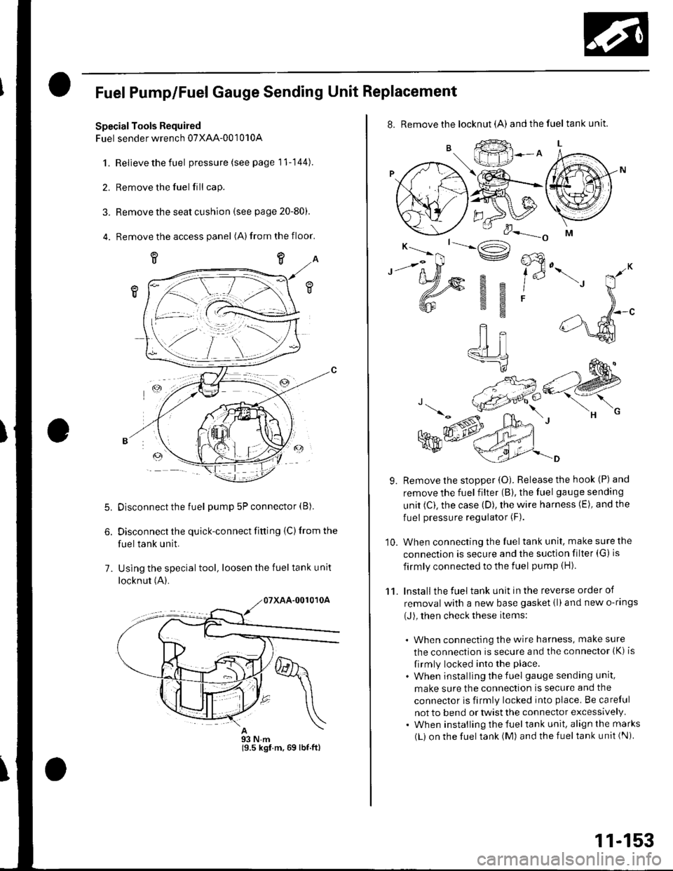
1.Relieve the fuel pressure (see page 11-144).
Remove the fuel fill cap.
Remove the seat cushion (see page 20-80).
Remove the access panel (A)from the floor.
5.
7.
Disconnect the fuel pump 5P connector (B).
Disconnect the quick-connect fitting {C) from the
fuel tank unit.
Using the special tool, loosen the fuel tank unit
locknut (A).
93 N.m19.5 kgf.m,69 lbf.ftl
11-153
8. Remove the locknut (A) andthefuel tankunit.
9. Remove the stopper {O). Release the hook (P) and
remove the fuel filter (B), the fuel gauge sending
unit (C). the case (D), the wire harness (E), and the
fuel pressure regulator (F).
10. When connecting the fuel tank unit, make sure the
connection is secure and the suction filter (G) is
firmly connected to the f uel pump (H).
11. Install the fuel tank unit in the reverse order of
removal with a new base gasket (l)and new o-rings
(J), then check these items:
. When connecting the wire harness, make sure
the connection is secure and the connector (K) is
firmly locked into the place.
. When installing the f uel gauge sending unit,
make sure the connection is secure and the
connector is firmly locked into place. Be careful
not to bend or twist the connector excessively.. When installing the fueltank unit, align the marks
(L) on the fuel tank (M) and the fuel tank unit (Ni
Page 416 of 1139
Manual Transmission
Transmission Removal (cont'd)
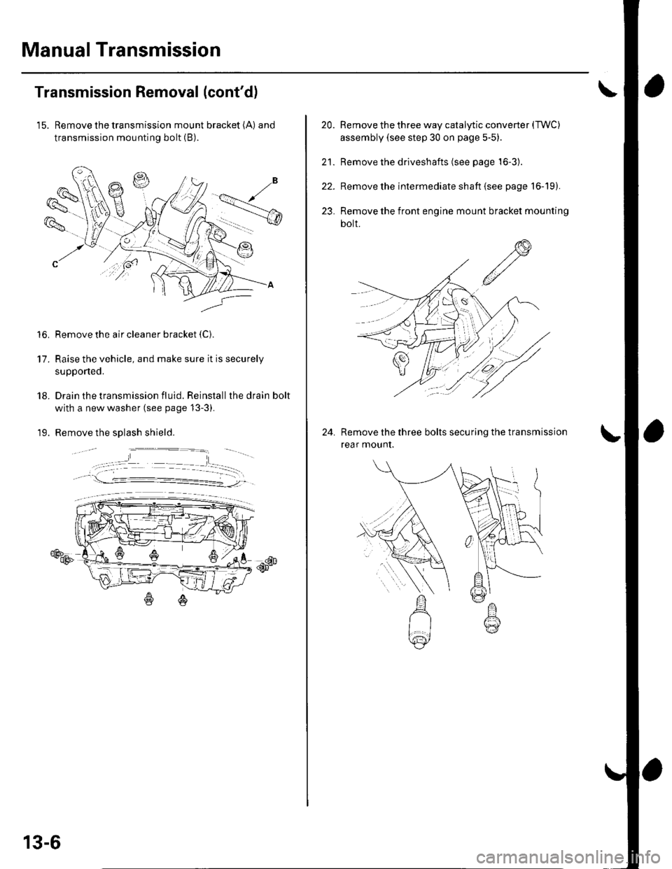
15. Remove the transmission mount bracket (A) and
transmission mounting bolt (B).
Remove the air cleaner bracket {C).
Raise the vehicle, and make sure it is securely
supponed.
Drain the transmission fluid. Reinstall the drain bolt
with a new washer (see page 13-3).
Remove the splash shield.
€Ds
to.
17.
18.
19.
db--qF
13-6
20.
21.
22.
23.
Remove the three way catalytic converter (TWC)
assembly (see step 30 on page 5-5)
Remove the driveshafts (see page 16-3).
Remove the intermediate shaft {see page 16-19).
Remove the front engine mount bracket mounting
bolt.
Remove the three bolts securing the transmission
rear mounI.
24.
Page 442 of 1139
Manual Transmission
Countershaft Assembly Clearance
Inspection (cont'd)
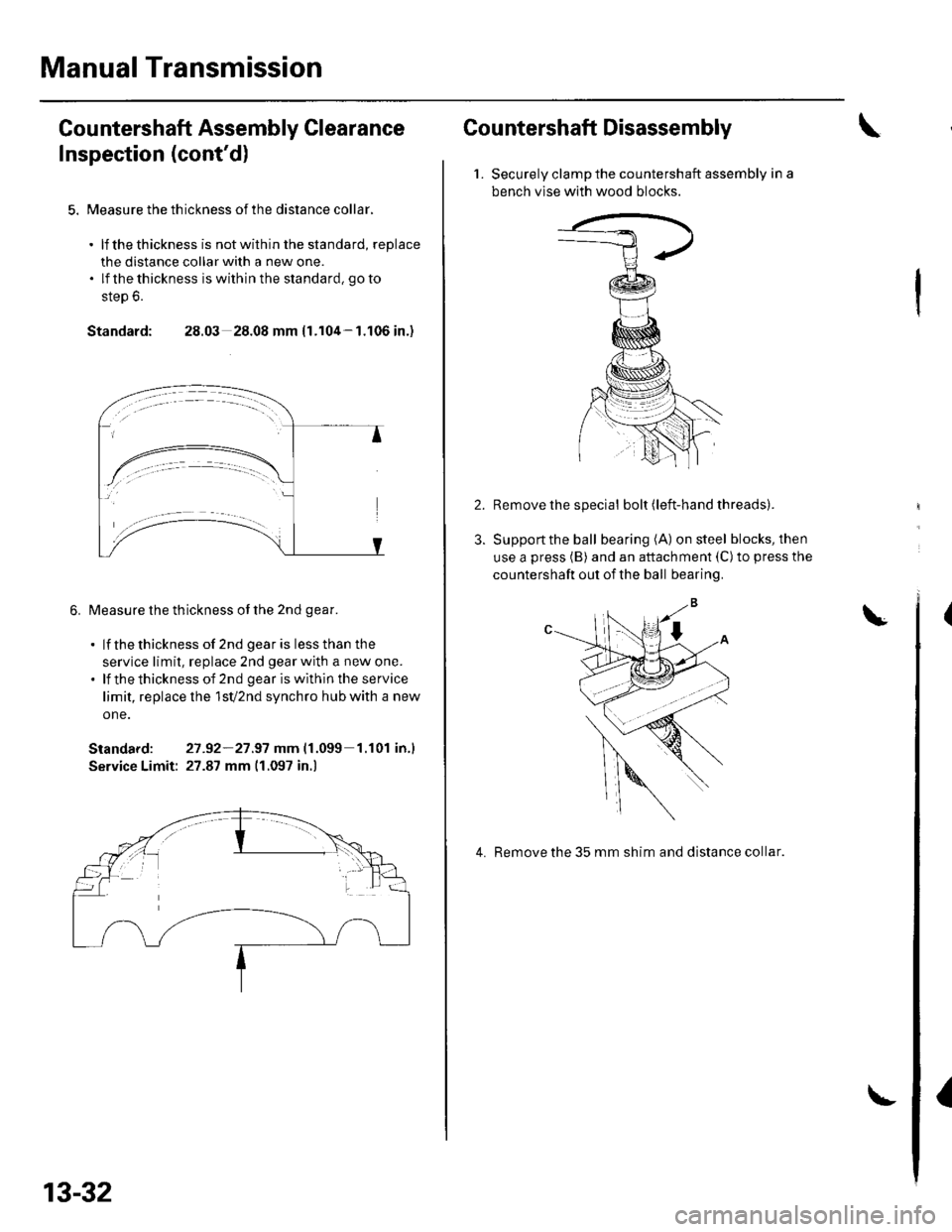
5. Measure the th ickness of the distance collar.
. lf thethickness is notwithin the standard, replace
the distance collar with a new one.. lf thethickness iswithinthe standard, goto
step 6.
Standard: 28.03 28.08 mm {1.104-1.106 in.)
6. Measure the thickness of the 2nd qear.
. lf thethickness of 2nd gearis lessthan the
service limit, replace 2nd gear with a new one.. lf thethicknessof 2nd geariswithintheservice
limit, replace lhe 1sV2nd synchro hub with a new
one.
Standard: 27 -92-21.97 mm|.1.099 1.r01 in.l
Service Limit: 27.87 mm 11.097 in.)
13-32
Countershaft Disassembly
1.Securely clamp the countershaft assembly in a
bench vlse with wood blocks.
Remove the special bolt (left-hand threads).
Support the ball bearing (A) on steel blocks, then
use a press (B) and an attachment (C)to press the
countershaft out of the ball bearing.
4. Remove the 35 mm shim and distance collar.
I
Page 458 of 1139
Manual Transmission
Transmission Reassembly (cont'dl
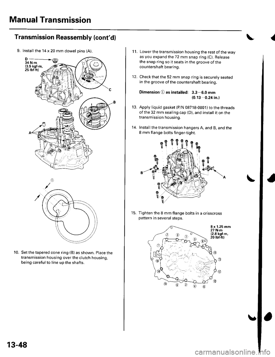
9. Install the 14 x 20 mm dowel pins (A).
34 N.m(3.5 kgf.m,25 rbf.ft)
Set the tapered cone ring (B) as shown. Place the
transmission housing over the clutch housing,
being careful to line up the shafts.
10.
13-48
11. Lower the transmission housing the rest of the wayas you expand the 72 mm snap ring {C). Release
the snap ring so it seats in the groove of the
countershaft bearing.
12. Check that the 52 mm snap ring is securely seatedin the groove of the countershaft bearing.
Dimension O as instalted: 3.3 6.0 mm
{0.13 0.24 in.l
Apply liquid gasket (P/N 08718-0001) to the threads
of the 32 mm sealing cap {D), and install it on thetransmission housing,
Install the transmission hangers A. and B, and the
8 mm flange bolts finger-tight.
13.
't4.
15.
8 x 1.25 mm27 N.m(2.8 kgf.m.20 rbf.ft)
(t
\A
e././
Tighten the 8 mm flange bolts in a crisscross
Pattern In several steDs.
(
Page 502 of 1139
Steering
Steering Column Removal
lnstallation
1.
4.
Install the steering column, and make sure the
wires are not caught or pinched by any parts.
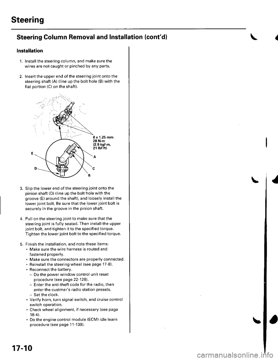
Insertthe upper end ofthe steering joint onto the
steering shaft {A) (line up the bolt hole (B) with the
flat portion (C) on the shaft).
8 x 1,25 mm28 N.m{2.9 kgf m,21 rbr.ft)
A
Slip the lower end of the steering joint onto the
pinion shaft {D) (line up the bolt hole with the
groove (E) around the shaft), and loosely lnstallthe
lower joint bolt. Be sure that the lower joint bolt is
securely in the groove in the pinion shaft.
Pull on the steering joint to make su re that the
steering joint is fully seated. Then installthe upper
joint bolt, and tighten it to the specified torque.
Tighten the lower joint bolt to the specified torque.
Finish the installation, and note these items:
. Make sure the wire harness is routed and
fastened properly.
. Make sure the connectors are properly connected.. Reinstallthe steering wheel (see page 17-8).
. Reconnect the battery.- Do the power window control unitreset
procedure {see page 22-128).- Enter the anti-theft code for the radio, then
enter the custmer's radio station presets.
- Set the clock.. Verify horn, turn signal switch, and cruise control
switch operation.. Check wheel alignment, if necessary (see page
18-4).. Do the engine control module (ECM) idle learn
procedu re {see page '11-139).
17-10
and Installation (cont'd){
Page 524 of 1139
DTC 22: Vehicle Speed Sensor Signal
DTC 23: Engine Speed Signal
NOTE:. lf the MIL indicator is ON, troubleshoot the PGIVI-Fl
system first.. Even though the system is operating normally, the
EPS indicator will come on under the following
conditions.
- Condition 1:. The vehicle was traveling at least '12.4 mph(20 km/h), then. A rapld change in vehicle speed was detected,
then. The vehicle (or the vehicle speed sensor signal)
stopped for at least 5 seconds, and. The engine speed was still 1,640 rpm or higher for
at least 5 seconds- Condition 2:
After the vehicle (or the vehicle speed sensor
signal) has stopped for at least 10 seconds, yetthe
engine speed was still 1,640 rpm or higher for at
least 20 seconds.- Condition 3:
When the vehicle speed is 10 km/h (6.2 mph) or
above and the engine is running at 280 rpm or
below for 3 seconds.
1. Start the engine and check the tachometer.
ls the tachometer working correctly?
YES- Go to step 2.
NO-Go to step 9.
2. Test-drive the vehicle above 15 km/h {9.3 mph).
ls the speedometer working correctly?
YES Go to step 3.
NO-Perform the speedometer system
troubleshooting {see page 22-651.a
3.Block the rear wheels and raise the vehicle, and
make sure it is securely supported.
Turn the ignition switch ON (ll).
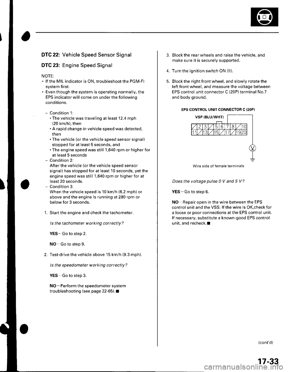
Block the right front wheel, and slowly rotate the
left front wheel, and measure the voltage between
EPS control unit connector C (20P)terminal No.7
and body ground.
EPS CONTROL UNIT CONNECTOR C {2OP)
Does the voltage pulse 0 V and 5 V?
YES Go to step 6.
NO Repair open in the wire between the EPS
control unit and the VSS. lf the wire is OK,check for
a loose or poor connections at the EPS control unit.
lf necessary, substitute a known-good EPS control
unit, and recheck.l
(conr'd)
4.
5.
Wire side of female terminals
17-33
Page 542 of 1139
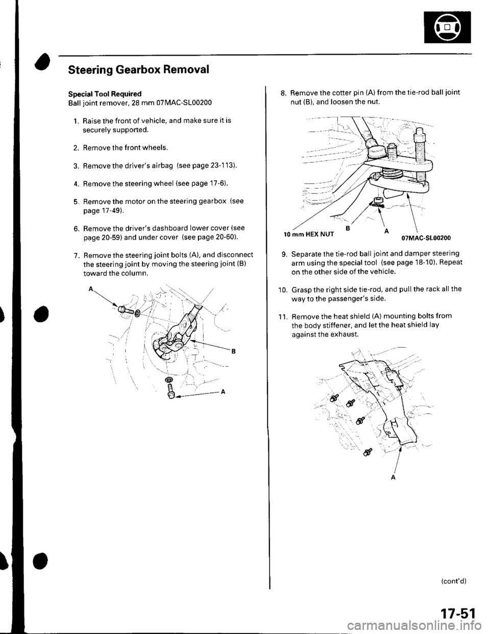
Steering Gearbox Removal
Special Tool Required
Ball ioint remover,2S mm 0TlvlAC-S100200
1. Raise the front of vehicle, and make sure it is
securely supponed.
2. Remove the front wheels.
Remove the driver's airbag (seepage23-113).
Remove the steering wheel (see page 17-6).
Remove the motor on the steering gearbox (see
page l T-49).
Remove the driver's dashboard lower cover (see
page 20-59) and under cover {see page20-60).
Remove the steering joint bolts (A), and disconnect
the steering joint by moving the steering joint (B)
toward the column.
4.
5.
6.
7.
'il
_t\
l- '/
,a.: --L -
8. Remove the cotter pin (A)from the tie-rod balljoint
nut {B), and loosen the nut.
r0 mm HEX NUT07MAC-S100200
Separate the tie-rod balljoint and damper steering
arm using the special tool (see page 18-10). Repeat
on the other side of the vehicle.
Grasp the right side tie-rod, and pull the rack all the
way to the passenger's side,
Remove the heat shield (A) mounting bolts from
the body stiffener, and let the heat shield lay
against the exhaust.
11.
9.
10.
(cont'd)
17-51
Page 548 of 1139
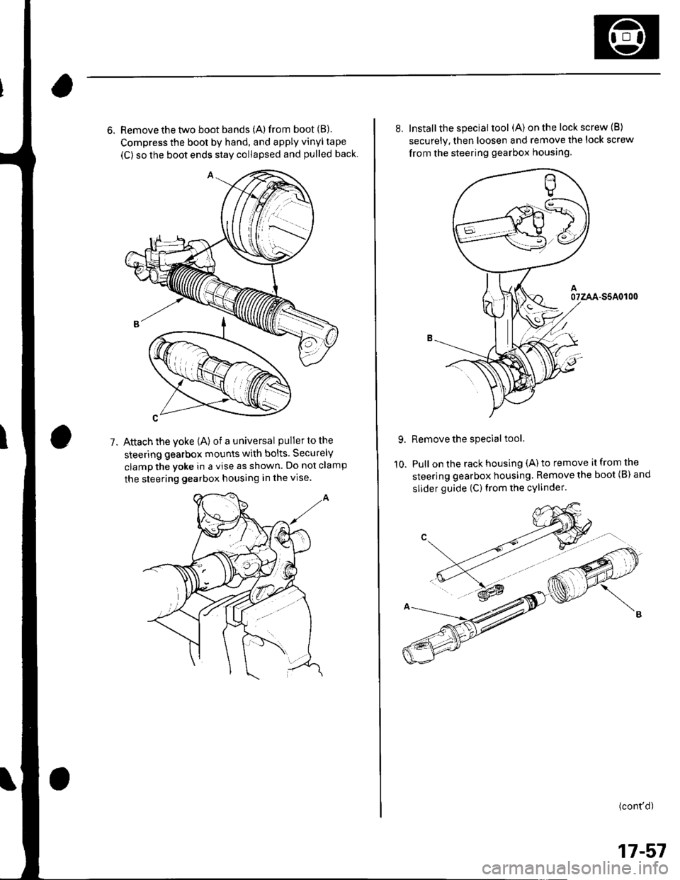
6. Remove the two boot bands (A) from boot (B).
Compress the boot by hand, and apply vinyl tape
(C) so the boot ends stay collapsed and pulled back
Attach the yoke (A) of a universal puller to the
steering gearbox mounts with bolts. Securely
clamp the yoke in a vise as shown. Do not clamp
the steering gearbox housing in the vise.
1.
10.
8. Installthe special tool (A) on the lock screw (B)
securely. then loosen and remove the lock screw
from the steering gearbox housing.
07zAA-S5A0r00
Remove the special tool.
Pull on the rack housing (A) to remove it from the
steering gearbox housing, Remove the boot {B) and
slider guide (C) from the cylinder.
(cont'd)
17-57