ECU HONDA CIVIC 2002 7.G User Guide
[x] Cancel search | Manufacturer: HONDA, Model Year: 2002, Model line: CIVIC, Model: HONDA CIVIC 2002 7.GPages: 1139, PDF Size: 28.19 MB
Page 187 of 1139
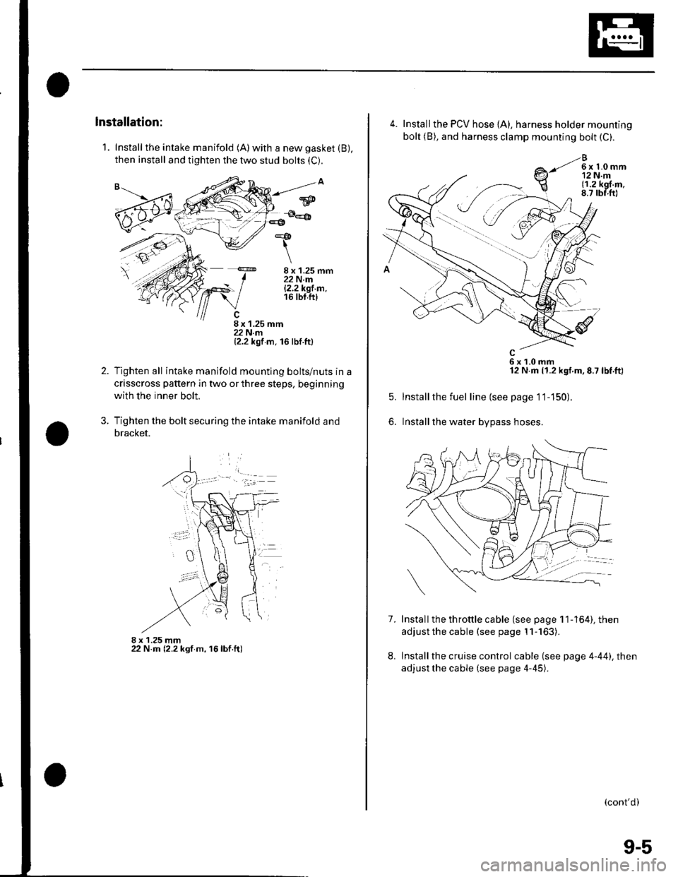
1. Install the intake manifold (A)with a new gasket (B),
then install and tighten the two stud bolts (C).
8 x 1.25 mm22 N.m|.2.2k91.m.16 tbt.ft)
8 x 1.25 mm22 N.rn(2.2 kgf m. 16 lbf.ttl
Tighten all intake manifold mountlng bolts/nuts in a
crisscross pattern in two or three steps, beginning
with the inner bolt.
Tighten the bolt securing the intake manifold and
bracket.
8 x 1.25 mm22 N.m (2.2 ksf m, 16lbf.ft)
*&
\
2.
?
w
4.
7.
5.
6.
Install the PCV hose {A), harness holder mounting
bolt (B), and harness clamp mounting bolt (C).
e-li*h,r
6x1.0mm12 N.m (1.2 kgf.m,8.7 lbf.ft)
Installthe fuel line (see page 11-150).
Installthe water bypass hoses.
Install the th rottle cable (see page 1 1-164), then
adjust the cable (see page 11-163).
Install the cruise control cable (see page 4-44). then
adjust the cable (see page 4-45).
8.
(cont'd)
9-5
Page 195 of 1139
1.
2.
Water Pump Inspection
Remove the drive belt (see page 4-26),
Turn the water pump pulley counterclockwise.
Check that it turns freely.
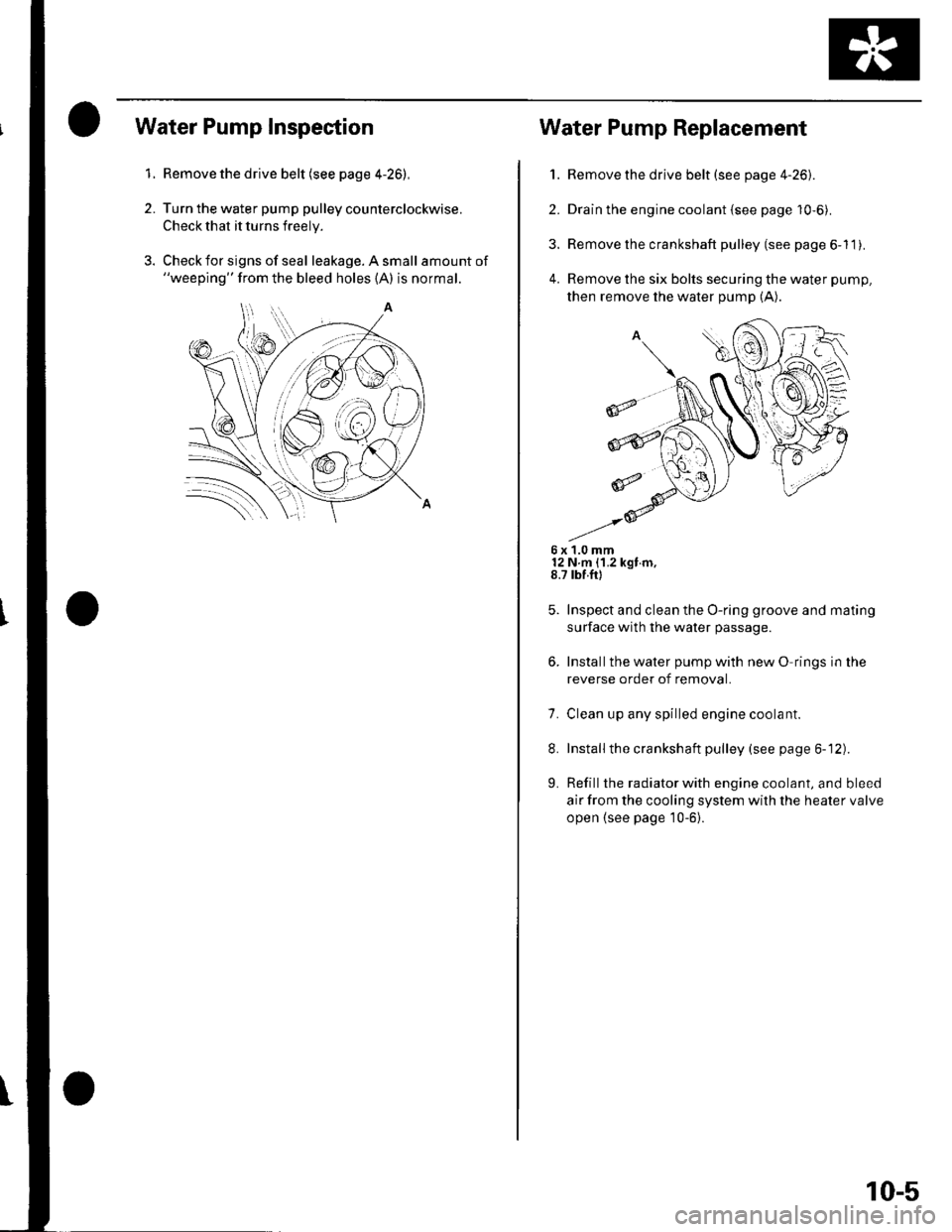
Check for signs of seal leakage. A small amount of"weeping" from the bleed holes (A) is normal.
Water Pump Replacement
1. Remove the drive belt (see page 4-26).
2. Drain the engine coolant {see page 10-6).
3. Remove the crankshaft pulley (see page 6-11).
4. Remove the six bolts securing the water pump,
then remove the water pump (A).
6x1.0mm12 N m {1.2 kgt m,8.7 rbf.ft)
Inspect and clean the O-ring groove and mating
surface with the water passage.
Installthe water pump with new O rings in the
reverse order of removal.
7. Clean up any spilled engine coolant.
8. Installthe crankshaft pulley (see page 6-12).
L Refill the radiator with engine coolant, and bleed
air from the cooling system with the heater valve
open {see page 10-6}.
10-5
Page 197 of 1139
1.
After the coolant has drained, tighten the radiator
drain plug securely. and installthe reserve tank
drain cap securely.
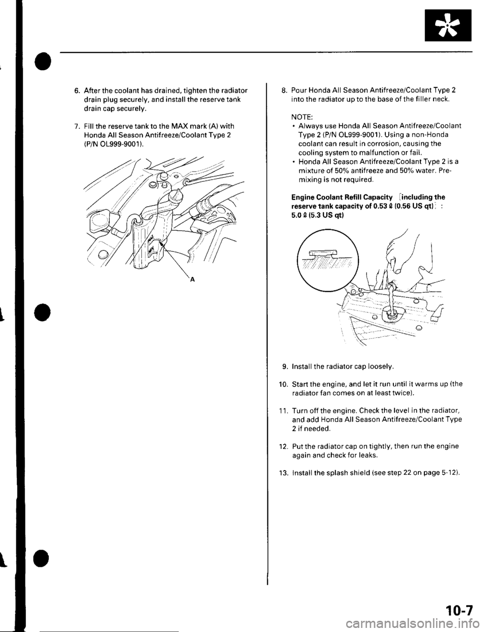
Fill the reserve tank to the MAX mark (A) with
Honda All Season Antifreeze/Coolant Tvpe 2
(P/N O1999-9001).
8. Pour Honda All Season Antifreeze/Coolant Type 2
into the radiator up to the base of the filler neck.
NOTE:. Always use Honda All Season Antifreeze/Coolant
Type 2 {P/N 01999-9001). Using a non-Honda
coolant can result in corrosion, causing the
cooling system to malfunction or fail.. Honda All Season Antifreeze/Coolant Type 2 is a
mixture of 50% antifreeze and 507o water. Pre-
mixing is not required.
Engine Coolant Refill Capacity including the
reserve tank capacity of 0.53 4 (0.56 US gtl :
5.0 0 (s.3 US qt)
Installthe radiator cap loosely.
Start the engine, and let it run until it warms up (the
radiator fan comes on at least twice).
Turn off the engine. Check the level in the radiator,
and add Honda All Season Antifreeze/Coolant Type
2 if needed.
Put the radiator cap on tightly, then run the engine
again and check for leaks.
lnstall the splash shield (see step 22 on page 5-12).
10.
11.
L
tJ.
10-7
Page 200 of 1139
Cooling System
Radiator and Fans Replacement
1. Drain the engine coolant (see page 10-6).
2. Remove the front bumper {see page 20,85).
3. Remove the bulkhead.
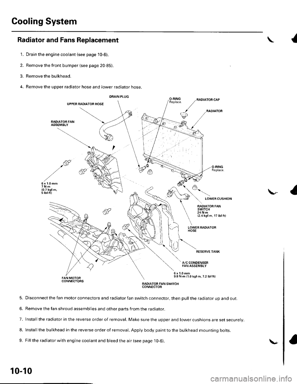
4. Remove the upper radiator hose and lower radiator hose.
DRAIN PLUG
UPPER BADIATOR HOSE
BAOIATOA FANASSEMBLY
{
O.RINGRADIATOR CAP
BADIATOB
LOWERCUSHION
\-
RADIATOR FANswtTcH24Nm{2.1t kgl m. 17lbl hl
LOWER FADIATORHOSE
RESERVETANK
A/C CONDENSERFAN ASSEMBLY
9.8 N m {1.0 kgf m,7.2 lbf ft)CONNECTORSRADIATOB FAN SWITCHCONNECTOB
5. Disconnect the fan motor connectors and radiator fan switch connector, then pull the radiator up and out.
6. Remove the fan shroud assemblies and other parts from the radiator.
7. Installthe radiator in the reverse order of removal. Make sure the upper and lower cushions are set securelV.
8. Install the bulkhead in the reverse order of removal. Apply body paint to the bulkhead mounting bolts.
9. Fill the radiator with engine coolant and bleed the air (see page 10-6).
10-10
\.
Page 211 of 1139
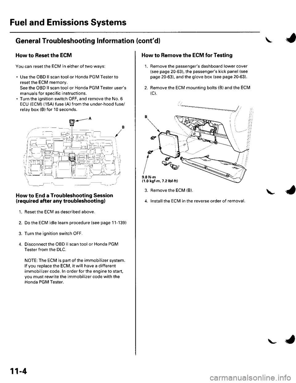
Fuel and Emissions Systems
General Troubleshooting Information (cont'dl
How to Reset the ECM
You can reset the ECM in either of two ways:
. Use the OBD ll scantool or Honda PGMTesterto
reset the ECM memory.
See the OBD ll scan tool or Honda PGI\4 Tester user's
manuals for specific instructions.' Turn the ignition switch OFF, and remove the No. 6
ECU {ECM} (15A) fuse (A)from the under-hood fuse/
relav box (Blfor 10 seconds.
How to End a Troubleshooting Session
(required after any troubleshootingl
1. Reset the ECM as described above.
2. Do the ECM idle learn procedure (see page 11-139)
3. Turn the ignition switch OFF.
4. Disconnectthe OBD ll scan tool or Honda PGM
Tester from the DLC.
NOTE: The ECM is part of the immobilizer system.
lf vou replace the ECM, it will have a different
immobilizer code. In order for the engine to start,
you must rewrite the immobilizer code with the
Honda PGM Tester.
11-4
\- ta
J
How to Remove the ECM for Testing
1. Remove the passenger's dashboard lower cover
{see page 20-63), the passenger's kick panel (see
page 20-63), and the glove box (see page 20-63).
2. Remove the ECM mounting bolts (B) and the ECM
(c),
9.8 N.m{1.0 kgf.m,7.2lbt.ft}
3. Remove the ECM (B).
4. Installthe ECM in the reverse order of removal.
L
Page 219 of 1139
Fuel and Emissions Systems
System Descriptions
Electronic Control System
The functions of the fuel and emlssion control systems are managed by the engine control module (ECM).
Fail-safe Function
When an abnormality occurs in the signal from a sensor, the ECI\4 ignores that signal and assumes a pre-programmed
value for that sensor that allows the enqine to continue to run.
Back-up Function
When an abnormality occurs in the ECM, the injectors are controlled by a back-up circuit independent of the system to
permit minimal driving.
Self-diagnosis
When an abnormality occurs in the signal from a sensor, the ECM supplies ground for the malfunction indicator lamp
{MlL) and stores the diagnostic trouble code {DTC) in erasable memory. When the ignition is first turned on, the EClvl
supplies ground to the l\4lL for 15 to 20 seconds to check the M lL bulb condition.
Two Driving Cycle Detection Method
To prevent false indications, the "two driving cycle detection method" is used for some self-diagnostic functions.
When an abnormality occurs, the ECM stores it in its memory. When the same abnormality recurs afterthe ignition
switch is turned OFF and ON (ll) again, the ECM turns on the MlL.
\
11-12
\.
\{
Page 222 of 1139
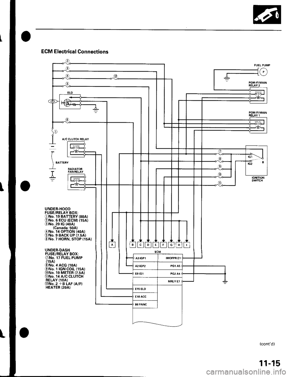
J/-\-1\_/
BEIAY2
A/C CLUTCH RELAY
RAOIATOR
I
)
T
UNDER.HOODFUSE/RELAY BOX:ONo. 19 BATTERY (8oA)ONo. 6 ECU (ECM) (15A1(3)No.20lG {40A1{Canada:50A}ONo. l4 OPTION {40A1€)No. 9 BACK uP (7.5A1lo)No. 7 HORN, STOP {15A}
UNDER.DASHFUSE/RELAY BOX:ONo. 17 FUEL PUMP{15A}@No. ,t ACG {10A)ONo. 1 IGN COIL (1sA)q)No. 10 METER (7.5A)0)No. 14 A/C CLUTCHRELAY IlOA)@No.2 +B LAF (A/F)HEATER (2OA)
(cont'd)
11-15
Page 278 of 1139
DTC P0300: Random Misfire and Any Combination of the Following:
DTC P0301: No. 1 Cylinder Misfire
DTC P0302: No. 2 Cvlinder Misfire
DTC P0303: No, 3 Cvlinder Misfire
DTC P0304: No. 4 Cvlinder Misfire
NOTE:. lfthe misfiring is frequent enough to trigger detection of increased emissions during two consecutive driving cycles.
the MIL will come on, and DTC P0300 (and some comlrination of P0301 through P0304) will be stored.. lf the misfiring is frequent enough to damage the catalyst, the MIL will blink whenever the misfiring occurs, and OTC
P0300 (and some combination of P0301 through P0304) will be stored. When the misfirlng stops, the MIL will remain
on.
1. Troubleshoot the following DTCs first if any of them were stored along with the random misfire DTC(s):
P0'107, P0108, P1128, P1129r N4anifold absolute pressure (MAP) sensor
P0111. P0'172t Fuel svstem
P0335. P0336: Crankshaft position (CKP) sensor
P0505: ldle control system
P1 149, Pl 162, P1 163, P1 164, P 1 165: Air fuel ratio (Ay'F) sensor
P1259: VTEC system
P1361, P1362: Camshaft position (CMP) sensor B {Top dead center (TDC) sensor)
P1519: ldle air control (lAC) valve
2. Test-drive the vehicle to verify the symptom.
3. Findthesymptom inthechart below, and dothe related procedures in the order listed until you find the cause.
SymptomProcedure(slAlso check foi:
Random misfire only
at low RPM and
under load
Check fuel pressure (see page 1 1-145).. Low compressron.. Low quality fuel.
Random misfire only
du ring acceleration
Check fuel pressure (see page 11-145).Malfunction in the
VTEC system (see page
1'�t-123).
Random misfire at
high RPM, under
load, or under
random conditions
Check fuel pressure (see page 11-145).Correct engine valve
clearances (see page 6-
91.
11-71
Page 279 of 1139
PGM-FI System
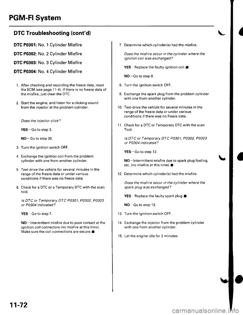
IDTC Troubleshooting (cont'dl
DTC P0301: No. 1 Cylinder Misfire
DTC P0302: No. 2 Cylinder Misfire
DTC P0303: No. 3 Cylinder Misfire
DTC P0304: No. 4 Cylinder Misfire
1. After checking and recording the freeze data, reset
the ECM (see page 1 1-4). lf there is no freeze data of
the misfire, just clear the DTC.
2. Start the engine, and listen for a clicking sound
from the injector at the problem cylinder.
Does the injector click?
YES-Go to step 3.
NO-Go to step 30.
3. Turn the ignition switch OFF.
4. Exchange the ignition coil from the problem
cylinder with one from another cylinder,
5. Test-drive the vehicle for several minutes in the
range of the freeze data or under va rious
conditions if there was no freeze data.
6. Check for a DTC or a Temporary DTC with the scan
root.
ls DTC or Tempotaty DTC P0301, P0302, P0303
or P0304 ind icated?
YES Go to step 7.
NO Intermittent misfire due to poor contact at the
ignition coil connectors {no misfire at this time).
Make sure the coil connections are secure.l
11-72
8.
9.
1.
11.
Determine which cylinder(s) had the misfire.
Does the misf ire occur in the cylinder where the
ignition coil was exchanged?
YES Replace the faulty ignition coil.!
NO-Go to step 8.
Turn the ignition switch OFF.
Exchange the spark plug from the problem cylinder
with one from another cylinder.
Test-drive the vehicle for several minutes in the
range of the freeze data or under various
conditions if there was no freeze data.
Check for a DTC or Temporary DTC with the scan
Tool.
ls DTC ot Tempotary DTC P0301, P0302, P0303
or P0304 ind icated?
YES Go to step 12.
NO Intermittent misfire due to spark plug fouling,
etc. (no misfire at this time).1
Determine which cylinder(s) had the misfire.
Does the misl ire occur in the cylinder where the
spark plug was exchanged?
YES Replace the faulty spark plug.l
NO Go to step 13.
Turn the ignition switch OFF.
Exchange the lnjector from the problem cylinder
with one from another cylinder.
Let the engine idle for 2 minutes.
10.
14.
t5.
Page 280 of 1139
16.Test-drive the vehicle for several minutes in the
range of the freeze data or under various
conditions if there was no freeze data.
Check for a DTC or a Temporary DTC with the scan
Tool.
ls DTC or Temporary DTC P0301, P0302, P0303
or P0304 indicated?
YES Go to step 18.
NO lntermittent misfire due to bad contact at the
injector connector (no misfire at this time). Make
sure the injector connection is secure. Check for
poor connections or loose terminals at the
injector.l
Determine which cylinder(s) had the misfire.
Does the misf ire occur in the cylinder where the
i njector w as exchanged ?
YES- Replace the faulty injector.I
NO-Go to step 19.
Turn the ignition switch OFF.
Disconnect the ignition coil 3P connector from the
problem cylinder.
Turn the ignition switch ON (ll).
't7 .
18.
19.
20.
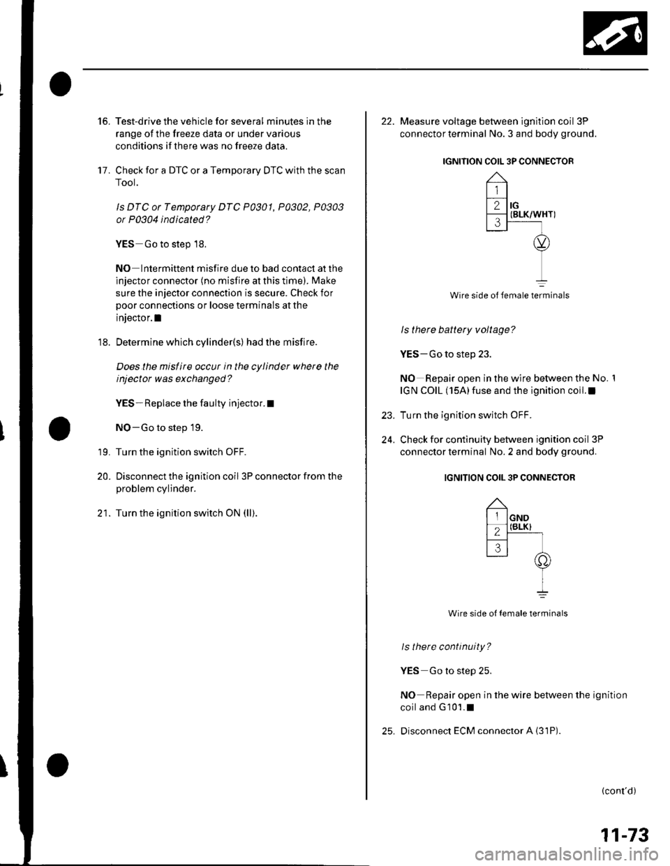
22. Measure voltage between ignition coil 3P
connector terminal No. 3 and body ground.
IGNITION COIL 3P CONNECTOR
Wire side ol female terminals
ls there battery voltage?
YES-Go to step 23.
NO Repair open in the wire between the No. 1
IGN COIL (15A)fuse and the ignition coil.I
Turn the ignition switch OFF.
Check for continuity between ignition coil 3P
connector terminal No. 2 and body ground.
IGNITION COIL 3P CONNECTOR
Wire side ot female terminals
ls there continuity?
YES Go to step 25.
NO Repair open in the wire between the ignition
coiland G101.1
Disconnect ECM connector A {31P)
23.
24.
(cont'd)
11-73