ECU HONDA CIVIC 2002 7.G Service Manual
[x] Cancel search | Manufacturer: HONDA, Model Year: 2002, Model line: CIVIC, Model: HONDA CIVIC 2002 7.GPages: 1139, PDF Size: 28.19 MB
Page 550 of 1139
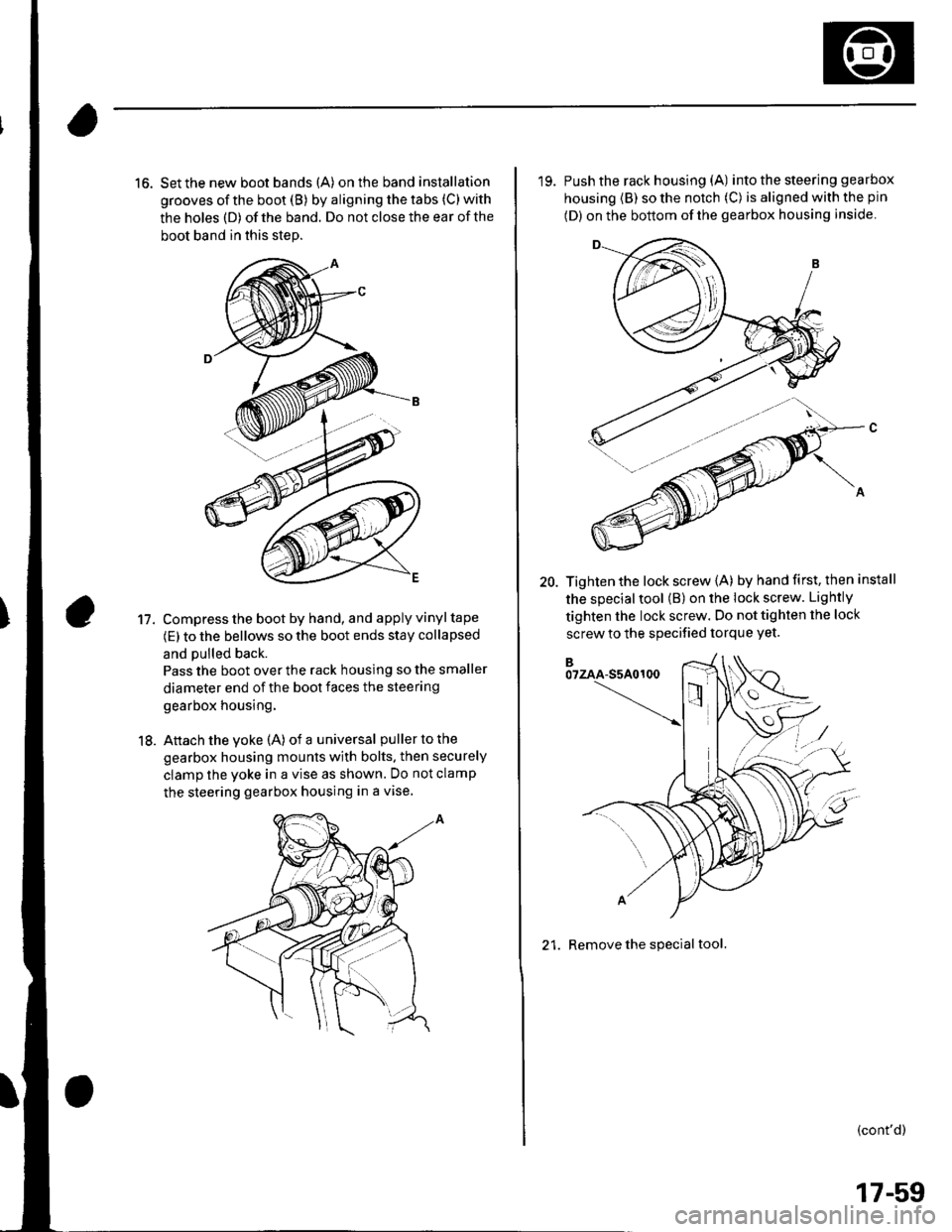
16. Set the new boot bands (A) on the band installation
grooves of the boot (B) by aligning the tabs (C) with
the holes (D) of the band. Do not close the ear of the
boot band in this step.
Compress the boot by hand, and apply vinyl tape
(E) to the bellows so the boot ends stay collapsed
and pulled back.
Pass the boot over the rack housing so the smaller
diameter end of the boot faces the steering
gearbox housing.
Attach the yoke (A) of a universal puller to the
gearbox housing mounts with bolts. then securely
clamp the yoke in a vise as shown. Do not clamp
the steering gearbox housing in a vise.
11.
18.
'19. Push the rack housing (A) into the steering gea rbox
housing (B) so the notch (C) is aligned with the pin
(D) on the bottom of the gearbox housing inside
20. Tighten the lock screw {A) by hand first, then install
the special tool (B) on the lock screw. Lightly
tighten the lock screw. Do not tighten the lock
screw to the specified torque Yet.
21. Remove the special tool.
(cont'd)
17-59
Page 551 of 1139
EPS Components
{Steering Gearbox Overhaul (cont'dl
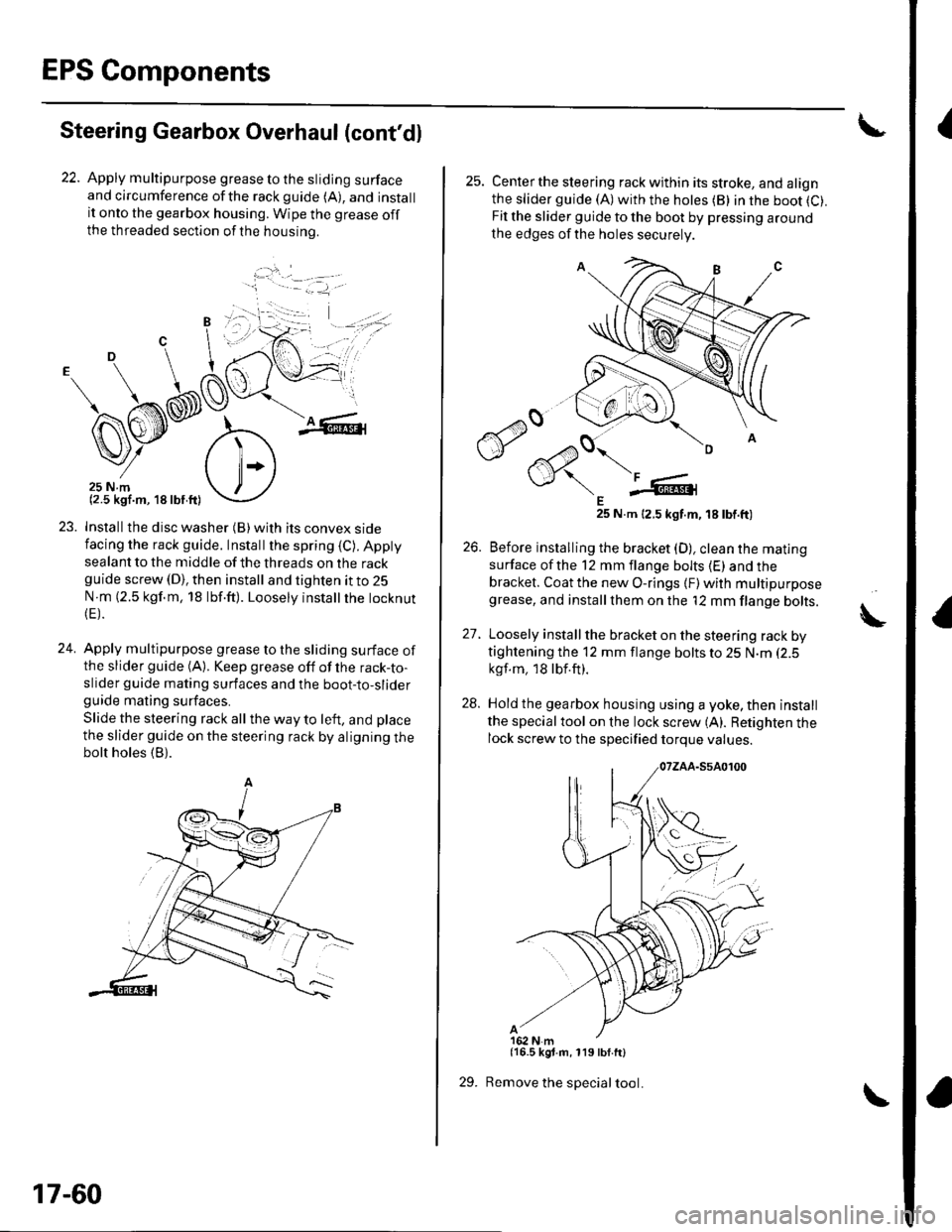
22. Apply multipurpose grease to the sliding surfaceand circumference ofthe rackguide (A), and installit onto the gearbox housing. Wipe the grease offthe threaded section ofthe housrno.
...'.
,. ,l
.j
23. Installthe disc washer (B)with its convex sidefacing the rack guide. Installthe spring (C). Appty
sealant to the middle of the threads on the rackguide screw (D), then install and tighten it to 25
N m (2.5 kgf.m, 18 lbf.ft). Loosely instatlrhe tocknut(E).
24. Apply multipurpose grease to the sliding surface ofthe slider guide (A). Keep grease off of the rack-to-slider guide mating surfaces and the boot-to-sliderguide mating surfaces.
Slide the steering rack all the way to left, and place
the slider guide on the steering rack by aligning thebolt holes (B).
'1 - .- =-1, -
17-60
29.
25. Centerthe steering rack within its stroke, and alignthe slider guide (A)with the hotes (B) in the boot (C).
Fit the slider guide to the boot by pressing around
the edges of the holes securely
E25 N.m 12.5 kgt.m, 18 tbt.ft)
26. Before installing the bracket (D), clean the mating
surface ofthe 12 mm flange bolts (E) and thebracket. Coat the new O-rings {F) with multipurposegrease, and installthem on the '12 mm flange bolts.
27. Loosely install the bracket on the steering rack bytightening the 12 mm flange bolts to 25 N.m (2.5
kgf.m, 18lbf.ft).
28. Hold the gearbox housing using a yoke, then install
the specialtool on the lock screw (A). Retighten thelock screw to the specified torque values.
{16.5 kgt.m, 119 lbf.ft}
Remove the special tool.
A
Page 557 of 1139
EPS Components
4
17.
18.
Steering Gearbox Installation (cont'dl
Install the motor on the steering gearbox (see page
17-49).
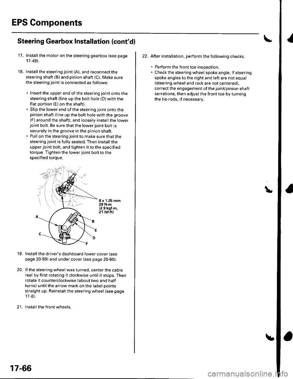
lnstall the steering joint (A). and reconnect the
steering shaft (B) and pinion shaft (C). Make sure
the steering joint is connected as follows:
. Insertthe upperend of thesteering jointontothe
steering shaft (line up the bolt hole (D) with the
flat portion (E) on the shaft).. Slip the lower end of the steering joint onto thepinion shaft (line up the bolt hole with the groove
(F) around the shaft), and loosely installthe lowerjoint bolt. Be sure that the lower joint bolt is
securely in the groove in the pinion shaft.. Pull on the steering joint to make sure that the
steering joint is fully seated. Then install the
upper joint bolt, and tighten it to the specified
torque. Tighten the lower joint bolt to the
specified torque.
8 x '1.25 mm28 N.m{2.9 kgf.m,21 tbt.ft)
19.
20.
Installthe driver's dashboard lower cover (see
page 20-59) and under cover (see page 20-60).
lf the steering wheel was turned, center the cable
reel by first rotating it clockwise until it stops. Then
rotate it counterclockwise (about two and half
turns) untilthe arrow mark on the label points
straight up. Reinstall the steering wheel (see page
17 -8).
Install the front wheels.)1
17-66
22. After installation, perform the following checks.
. Perform the front toe inspection.. Check the steering wheel spokeangle. lfsteering
spoke angles to the right and left are not equal(steering wheel and rack are not centered),
correct the engagement of the joinvpinion shaft
serrations, then adjust the front toe by turning
the tie-rods, if necessarv.
\
Page 566 of 1139
Front and Rear Suspension
Wheel Alignment (cont'dl
Turning Angle Inspection
Use commercially-available computerized four wheel
alignment equipment to measure wheel alignment(caster. camber, toe, and turning angle). Followthe
equiDment manufacturer's instructions.
1. Turn the steering wheel fullytotherightandleft
while applying the brake, and check the turning
angles of both front wheels, lf the turning angle is
not within the specification or the inward turning
angles differ between the right and left side, go to
steD 2.
Turning angle:
lnward: 34'00'+ 2'
Outward: 28'00' {reference)
Check the toe. lf it is correct, but the turning angle
is not within the specification, check ior bent or
damaged suspension components,
18-8
Wheel Bearing End Play Inspec'tion
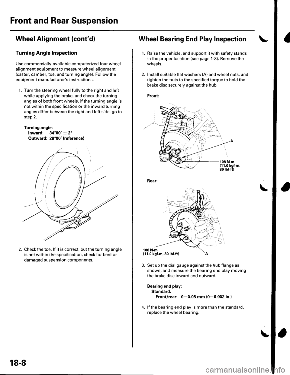
1. Raise lhe vehicle, and support it with safety stands
in the proper location (see page 1-8). Remove the
wheels.
2. Install suita ble f lat washe rs (A) and wheel nuts, and
tighten the nuts to the specified torque to hold the
brake disc securely against the hub.
Front:
108 N.m(11.0 kgf.m,80 rbf.ft)
Rear:
108 N.m
3. Set up the dial gauge against the hub flange as
shown, and measure the bearing end play moving
the brake disc inward and outward.
Bearing end play:
Standard:
Front/rear: 0 0.05 mm {0 0.002 in.}
4. lf the bearing end play is more than the standard,
replace the wheel bearing.
\
(11.0 kgf.m,80 lbf.ft)
Page 573 of 1139
18.
19.
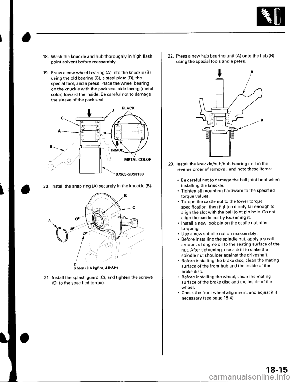
Wash the knuckle and hub thoroughly in hlgh flash
point solvent before reassembly.
Press a new wheel bearing (A) into the knuckle (B)
using the old bearing (C), a steel plate {D). the
special tool, and a press. Place the wheel bearing
on the knuckle with the pack seal side facing (metal
color) toward the inside. Be careful not to damage
the sleeve of the pack seal.
"-t-_"*,,''
_, .' . . a-�.) ../
..-.
20. Install the snap ring (A) securely in the knuckle (B).
D6 N.m 10.6 kgf.m,4lbf ft)
lnstall the splash guard (C), and tighten the screws
(D) to the specified torque.
23.
22. Press a new hub bearing unit {A) ontothehub(B)
using the special tools and a press.
Installthe knuckle/hub/hub bearing unit in the
reverse order of removal, and note these items:
. Be careful notto damagethe balljoint bootwhen
installing the knuckle.. Tighten all mounting hardware to the specified
lOrque values.. Torque the castle nut to the lower torque
specification, then tighten it only far enough to
align the slot with the ball joint pin hole. Do not
align the castle nut by loosening it.
. Install a new look pin on the castle nut after
torquing.. Use a new spindle nut on reassembly.. Before installing the spindle nut, apply a small
amount of engine oil to the seating surface of the
nut. After tightening, use a drift to stake the
spindle nut shoulder against the driveshaft.
. Before installlng the brake disc, clean the mating
surface of the front hub and the inside of the
brake disc.. Before installing the wheel, clean the mating
su rface of the brake disc and the inside of the
wneet.. Check the front wheel alignment, and adjust it if
necessary (see page 18-4).
18-15
Page 603 of 1139
Conventional Brake Components
Brake System Bleeding
NOTE:. Do not spill brake fluid on the vehicle; it may damage
the painU if brake fluid does contact the paint. wash it
off immediately with water.. The reservoir on the master cylinder must be at the
MAX (upper) level mark at the start of the bleeding
procedure and checked after bleeding each brake
caliper. Add fluid as required.. Do not reuse the drained fluid.. Always use Honda DOT 3 brake fluid. Non-Honda
brake fluid can cause corrosion and shorten the life of
the system.. Make sure no din or other foreign matter is allowed
to contaminate the brake fluid.
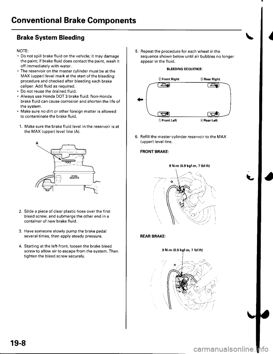
1. Make sure the brake fluid level in the reservoir is at
the MAX (upper) level line (A).
Slide a piece of clear plastic hose over the flrst
bleed screw, and submerge the other end in a
container of new brake fluid.
Have someone slowly pump the brake pedal
severaltimes, then apply steady pressure.
Starting at the left-front, loosen the brake bleed
screw to allow air to escape from the system. Then
tighten the bleed screw securely.
2.
19-8
5. ReDeatthe procedure for each wheel in the
sequence shown below until air bubbles no longer
appear in the fluid.
BLEEDING SEOUENCE:
OFront RightORe.r Right
O Front LeftORoar Loft
Refill the master cylinder reservoir to the MAX
{upper) level line.
FRONT BRAKE:
9 N.m 10.9 kgf.m,7 lbl.ft)
t-
REAR BRAKE:
9 N m 10.9 kgf.m, 7 lbf ft)
Page 608 of 1139
Front Brake Disc lnspection
Runout
1. Raise the front of the vehicle, and support it with
safety stands in the proper location (see page 1-8).
Remove the front wheels.
2. Remove the brake pads (see page 19-11).
3. Inspect the disc surface for damage and cracks.
Clean the disc thoroughly, and remove all rust
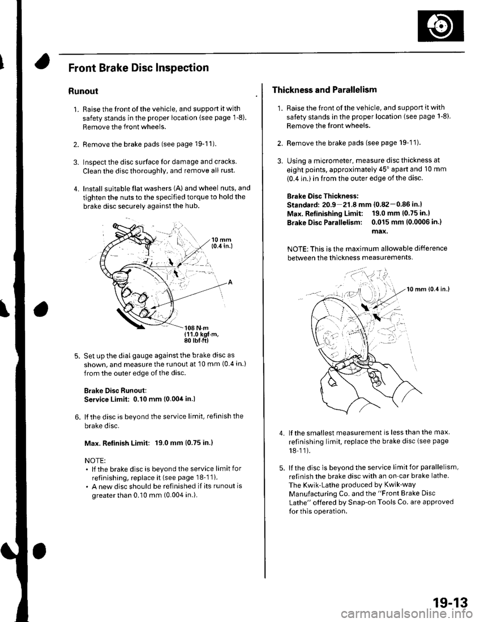
4. lnstall suita ble flat washers (A) andwheel nuts,and
tighten the nuts to the specified torque to hold the
brake disc securely against the hub.
Set up the dial gauge against the brake disc as
shown, and measure the runout at 10 mm (0 4 in.)
from the outer edge of the disc.
Brake Disc Runout:
Service Limit: 0.10 mm (0.00tt in.l
lf the disc is beyond the service limit, refinish the
brake disc.
Max. Retinish Limit: 19.0 mm (0.75 in.)
NOTE:. lf the brakedisc is beyondtheservice limitfor
refinishing, replace it (see page 18-1 1).
. A new disc should be refinished if its runout is
greater than 0.10 mm (0.004 in.).
Thickness and Parallelism
1. Raise the front of the vehicle, and support it with
safety stands in the proper location (see page 1-8).
Remove the front wheels.
2. Remove the brake pads (see page 19-11).
3. Using a micrometer, measure disc thickness at
eight points, approximately 45" apart and 10 mm
{0.4 in.) in from the outer edge of the disc.
Brake Oisc Thickness:
Standard: 20.9 21.8 mm {0.82-0.86 in.}
Max. Refinishing Limit: 19.0 mm 10.75 in.)
Brake Disc Parallelism: 0.015 mm 10.0(X)6 in.)
max.
NOTE: This is the maximum allowable difference
between the thickness measurements
10 mm lo.it in.l
lf the smallest measurement is less than the max.
refinishing limit, replace the brake disc (see page
18-11).
lf the disc is beyond the service limit for parallelism,
refinish the brake disc with an on-car brake lathe.
The Kwik-Lathe produced by Kwik-way
Manufacturing Co. and the "Front Brake Disc
Lathe" offered by Snap-on Tools Co. are approved
for this operation.
4.
': . --'t-'"'-
t,.
19-13
Page 612 of 1139
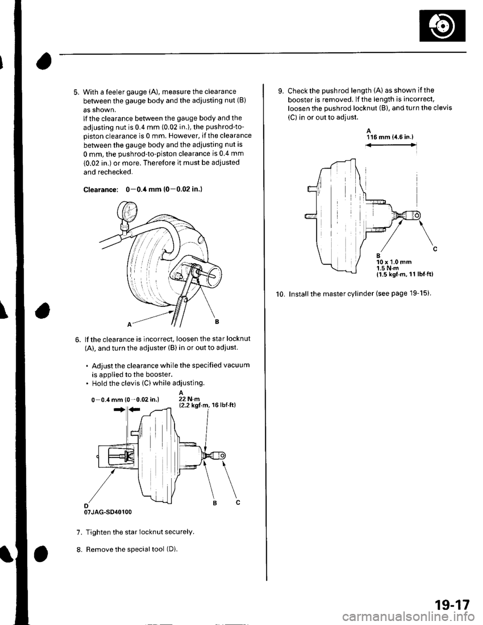
5. With a feeler gauge (A), measure the clearance
between the gauge body and the adjusting nut (B)
as snown,
lf the clearance between the gauge body and the
adjusting nut is 0.4 mm (0.02 in.), the pushrod-to-
piston clearance is 0 mm. However. if the clearance
between the gauge body and the adjusting nut is
0 mm, the pushrod-to-piston clearance is 0 4 mm
{0.02 in.) or more. Therefore it must be adjusted
and rechecked.
Clearance: 0-0./t mm (0-0.02 in.)
lf the clearance is incorrect, loosen the star locknut
(A). and turn the adjuster (B) in or out to adjust.
. Adjust the clearance while the specified vacuum
is appiied to the booster.. Hold the clevis (C) while adjusting.
A0 0.4 mm l0 -0.02 in.) 22N.n
07JAG-SO40100
7. Tighten the star locknut securely.
8. Remove the special tool (D).
9. Check the pushrod length (A) asshownifthe
booster is removed, lf the length is incorrect,
loosen the pushrod locknut (B), and turn the clevis
(C) in or out to adjust.
A116 mm {4.6 in.)
10. Installthe master cylinder (see page l9-15)
10 x 1.0 mm1.5 N'm11.5 kgf.m,11 lbf.ftl
19-17
Page 613 of 1139
Gonventional Brake Components
IBrake Booster Test
Functional Test
1. With the engine stopped, press the brake pedal
several times to deplete the vacuum reservoir, thenpress the pedal hard, and hold itfor 15 seconds. lfthe pedal sinks, either the master cylinder is
bypassing internally, or the brake system (master
cylinder, lines. modulator, or calipers) is leaking.
2. Start the engine with the brake pedal pressed. lf thepedal sinks slightly, the vacuum booster is workingproperly. lf the pedal height does not vary, thebooster or check valve is faulty.
3. With the engine running, press the brake pedal
lightly. lfthe brake pedal sinks more than 1O mm
{3/8 in, ) in 3 minutes, the master cylinder is faulty.A slight change in pedal height when the Ay'C
compressor cycles on and off is normal. (The A,/C
compressor load changes the vacuum available tothe booster.)
Leak Test
1. Press the brake pedal with the engine running, thenstop the engine. lf the pedal height does not vary
while pressed for 30 seconds, the vacuum boosteris OK. lf the pedal rises, the booster is faulty.
2. With the engine stopped, press the brake pedal
several times using normal pressure. When thepedal is first pressed, it should oe row.
On consecutive applications, the pedal height
should gradually rise. lfthe pedal position does notvarv, check the booster check valve.
19-18
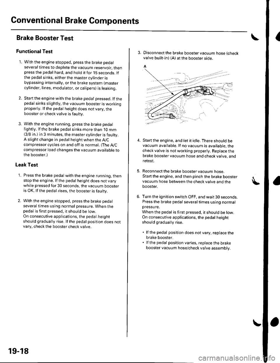
3. Disconnect the brake booster vacuum hose (check
valve built-in) (A) at the booster side.
5.
4.Start the engine, and let it idle. There should bevacuum available. lf no vacuum is available, thecheck valve is not working properly. Repiace thebrake booster vacuum hose and check valve, andrelesI.
Reconnect the brake booster vacuum nose.
Start the engine, and then pinch the brake boostervacuum hose between the check valve and thebooster,
Turn the ignition switch OFF, and wait 30 seconds,Press the brake pedal several times using normalpressu re,
When the pedal is first pressed, it should be low.On consecutive applications, the pedal height
should gradually rise.
. lf the pedal position does notvary, replacethe
brake booster.. lf the pedal position varies, replace the brake
booster vacuum hose/check valve assembly.
Page 617 of 1139
Conventional Brake Components
Rear Brake Disc Inspection
Runout
1. Raise the rear of the vehicle, and support it with
safety stands in the proper location (see page 1-8).Remove the rear wheels,
2. Remove the brake pads (see page 19-20).
3. Inspect the disc surface for damage and cracks.
Clean the disc thoroughly, and remove all rust,
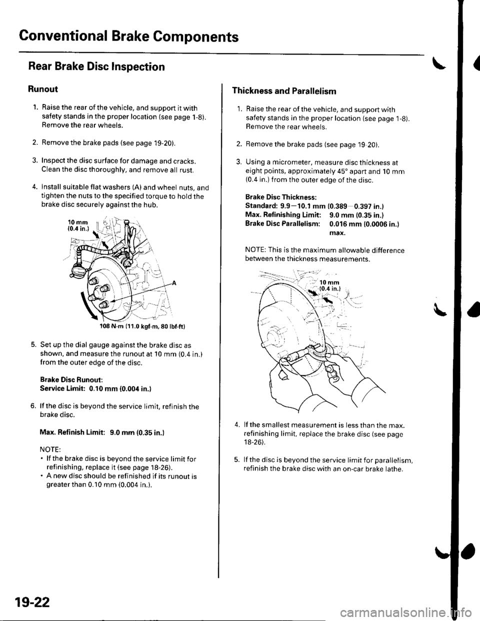
4. lnstall suita ble f lat washers (A) and wheel nuts, andtighten the nuts to the specified torque to hold thebrake disc securely against the hub.
108 N.m (11.0 kgf.m,80lbf.ft)
Set up the dial gauge against the brake disc as
shown. and measure the runout at 10 mm (0.4 in.)
from the outer edge of the disc.
Brake Disc Runout;
Service Limit: 0.10 mm {0.004 in.)
lf the disc is beyond the service limit, refinish thebrake disc.
Max. Refinish Limit: 9.0 mm (0.35 in.)
NOTE:. lf the brake disc is beyondtheservice limitfor
refinishing, replace it (see page 18-26).. A new disc should be refinished if its runout isgreater than 0.10 mm (0.004 in.).
19-22
Thickness and Parallelism
1. Raise the rear of the vehicle, and support with
safety stands in the proper location (see page l-g).Remove the rear wheels.
2. Remove the brake pads {see page 19 20).
3, Using a micrometer, measure disc thickness ateight points, approximately 45'apart and 10 mm
{0.4 in.) from the outer edge of the disc.
Brake Disc Thickness:
Standard: 9.9-10.1 mm (0.389 0.397 in.l
Max. Retinishing Limit: 9.0 mm (0.35 in.)
Brake Disc Parallelism: 0.016 mm 10.0006 in.)
max.
4.lf the smallest measurement is less than the max.
refinishing limit, replace the brake disc (see page
18-26).
lf the disc is beyond the service limit for parallelism,
refinish the brake disc with an on-car brake lathe.