boot HONDA CIVIC 2002 7.G Owner's Guide
[x] Cancel search | Manufacturer: HONDA, Model Year: 2002, Model line: CIVIC, Model: HONDA CIVIC 2002 7.GPages: 1139, PDF Size: 28.19 MB
Page 552 of 1139
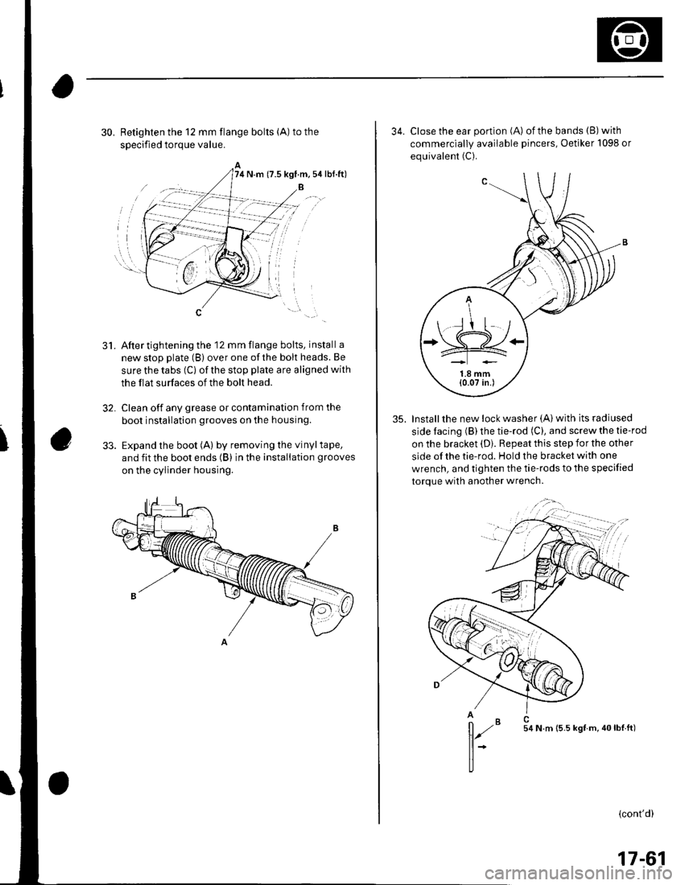
30, Retighten the 12 mm flange bolts (A) to the
soecified toroue value.
After tightening the 12 mm flange bolts, install a
new stop plate (B) over one of the bolt heads. Be
sure the tabs (C) of the stop plate are aligned with
the flat surfaces of the bolt head.
Clean off any grease or contamination from the
boot installation grooves on the housing.
Expand the boot (A) by removing the vinyltape,
and fit the boot ends (B) in the installation grooves
on the cylinder housing.
5t.
32,
74 N.m (7.5 kgf.m,5ir lbf.ft)
34. Close the ear portion (A) ofthe bands (B)with
commerciallv available pincers, Oetiker 1098 or
equivalent (C).
35. Installthe new lock washer (A) with its radiused
side facing (B) the tie-rod (C), and screw the tie-rod
on the bracket (D). Repeat this step for the other
side of the tie-rod. Hold the bracket with one
wrench, and tighten the tie-rods to the specified
torque with another wrench.
,,";=-...,.,
(cont'd)
*=,,',
17-61
Page 558 of 1139
EPS Control Unit Removal/
Installation
1. Remove the passenger's under panel.
2. Turn up the floor carpel, remove lhe EPS control
untr.
Disconnect the EPS control unit connectors.
lnstallthe EPS control unit in the reverse order of
removal.
After installation, start the engine, and let it idle.
Turn the steering wheelfrom lock-to-lock several
times. Check that the EPS indicator does not come
on.
3.
E
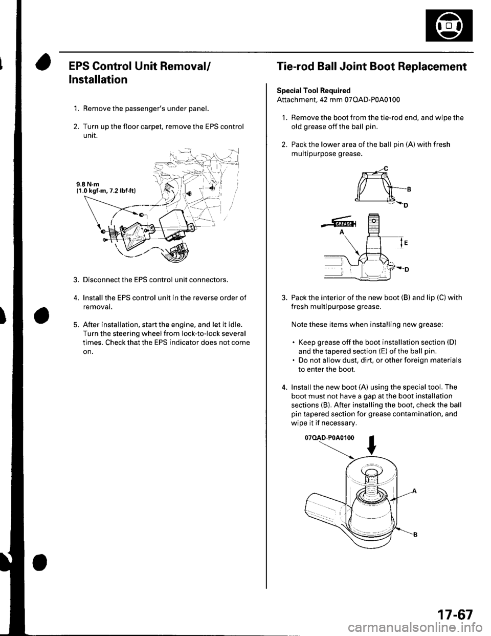
Tie-rod Ball Joint Boot Replacement
Special Tool Required
Attachment, 42 mm 07OAD-P0A0100
l. Remove the boot from the tie-rod end, and wipe the
old grease off the ball pin.
2. Pack the lower area of the ball pin(A)wilhfresh
mulr purpose grease.
3. Pack the interior of the new boot (B) and lip (C) with
fresh multipurpose grease.
Note these items when installing new grease;
. Keep grease offthe boot installation section (D)
and the tapered section (E) of the ball pin.
. Do not allow dust, dirt, or other foreign materials
to enter the boot.
4. Installthe new boot (A) using the specialtool. The
boot must not have a gap at the boot installation
sections (B). After installing the boot. check the ball
pin tapered section for grease contamination, and
wipe it if necessary.
07(lAD-P0A0100
*-4
r/ \-,d______i.l+_D
-6rA
17-67
Page 559 of 1139
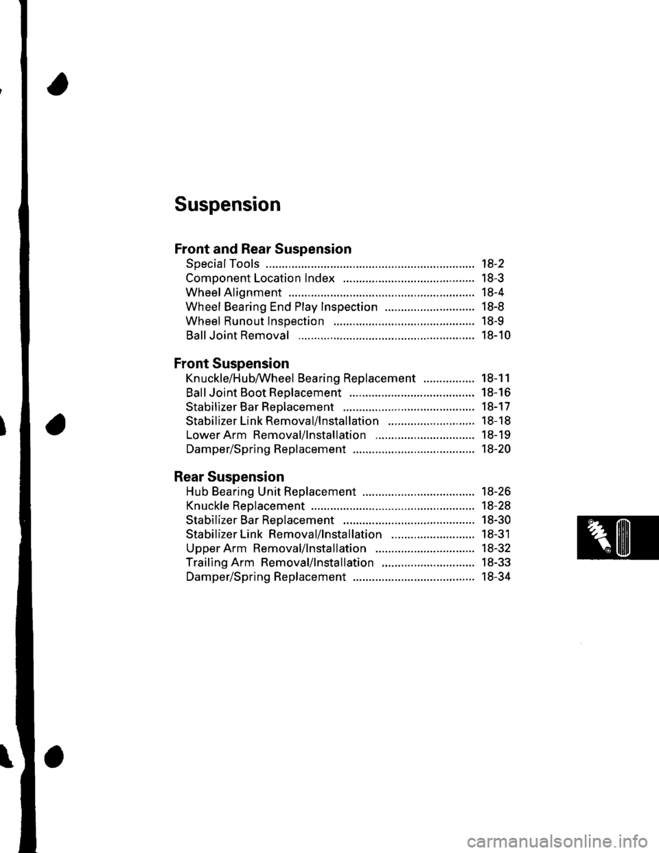
Suspension
Front and Rear Suspension
SpecialTools ............. 18-2
Component Location Index ......................................... 18-3
Wheel Alignment ..................... ........... 18-4
Wheel Bearing End Play Inspection ............................ 18-8
Wheel Runout Inspection .................. 18-9
Ball Joint Removal ... 18-10
Front Suspension
Kn uckle/H u bAVheel Bearing Replacement
Ball Joint Boot Reolacement ..................
Stabilizer Bar Rep|acement ....................
Stabilizer Link Removal/lnstallation
LowerArm Removal/lnstallation ...............
Damper/Spring Replacement
Rear Suspension
Hub Bearing Unit Replacement .....................
Knuckle Reolacement
Stabilizer Bar Replacement ....................
Stabilizer Link Removal/lnstallation ..........................
Upper Arm Removal/lnstallation ...............
Trailing Arm Removal/lnstallation
Damper/Spring Replacement
18-1 1
18-16
18-17
18-18
18-19
18-20
18-26
18-28
18-30
18-31
18-32
18-33
18-34
Page 561 of 1139
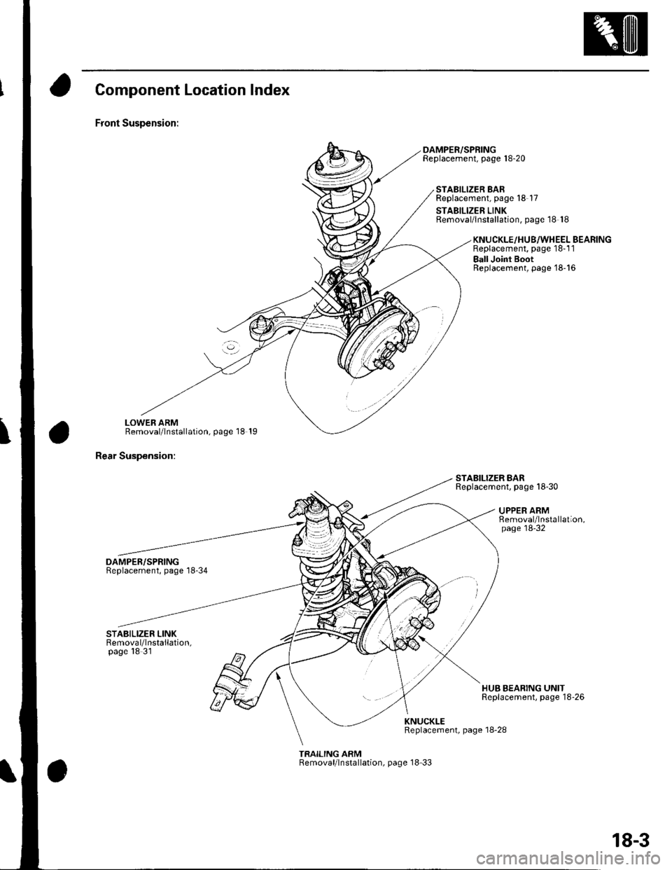
Component Location Index
Front Suspension:
LOWEB ARMRemoval/lnstallation, page 18 19
Rear Suspension:
DAMPER/SPRINGReplacement, page'18-34
DAMPER/SPRINGReplacement, page 18-20
STABILIZER BARReplacement, page 18-17
STABILIZER LINKRemoval/lnstallation, page 18 18
STABILIZER BARReplacement. page 18-30
KNUCKLE/HU8/WHEEL BEARINGReplacement, page 18-1 1
Ball Joint BootReplacement, page'18-16
UPPER ARMRemoval/lnstallation,page'18-32
HUB BEARING UNITReplacement, page 18'26
KNUCKLEReplacement, page 18-28
TRAILING ARMRemoval/lnstallation, page 18 33
18-3
Page 568 of 1139
Front and Rear Suspension
BallJoint Removal
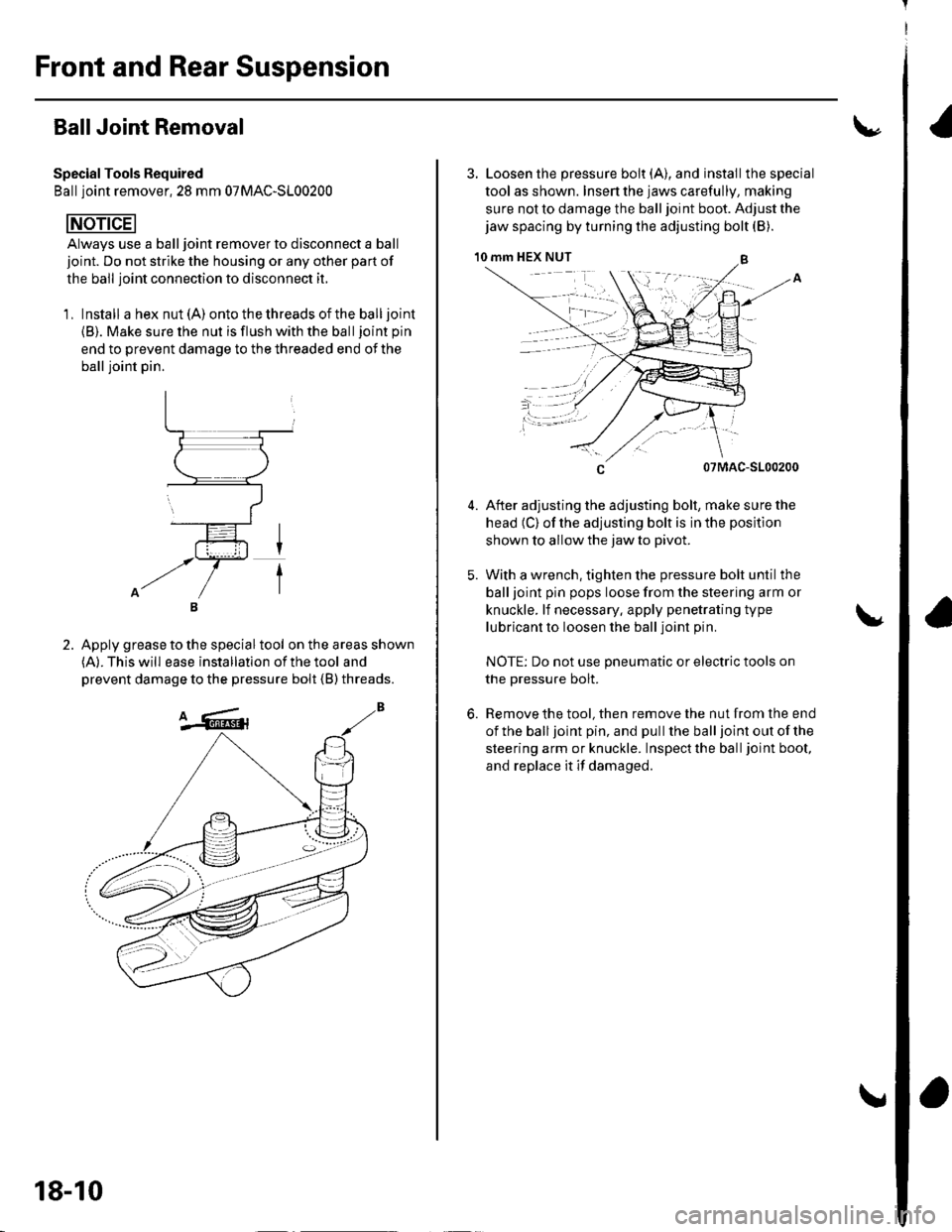
Special Tools Required
Ball ioint remover.2S mm 07MAC-SL00200
Always use a ball joint remover to disconnect a ball
joint. Do not strike the housing or any other part of
the ball joint connection to disconnect it.
'1, Install a hex nut (A) ontothethreadsoftheballjoint
{B). Make sure the nut is flush with the balljoint pin
end to prevent damage to the threaded end of the
ball ioint oin.
Apply grease to the special tool on the areas shown(A). This will ease installation of the tool and
prevent damage to the pressure bolt {B) threads.
2.
18-10
3. Loosen the pressure bolt (A), and installthe special
tool as shown. Insen the jaws carefully, making
sure not to damage the ball joint boot. Adjust the
jaw spacing by turning the adjusting bolt (B).
10 mm HEX NUT
5.
07MAC-S100200
After adjusting the adjusting bolt, make sure the
head (C) of the adjusting bolt is in the position
shown to allow the jaw to pivot.
With a wrench, tighten the pressure bolt until the
ball ioint pin pops loose from the steering arm or
knuckle. lf necessary. apply penetrating type
lubricant to loosen the ball joint pin
NOTE: Do not use pneumatic or electric tools on
the pressure bolt.
Remove the tool, then remove the nut from the end
ofthe balljoint pin, and pullthe balljoint out ofthe
steering arm or knuckle. Inspectthe balljoint boot,
and replace it if damaged.
6.
Page 573 of 1139
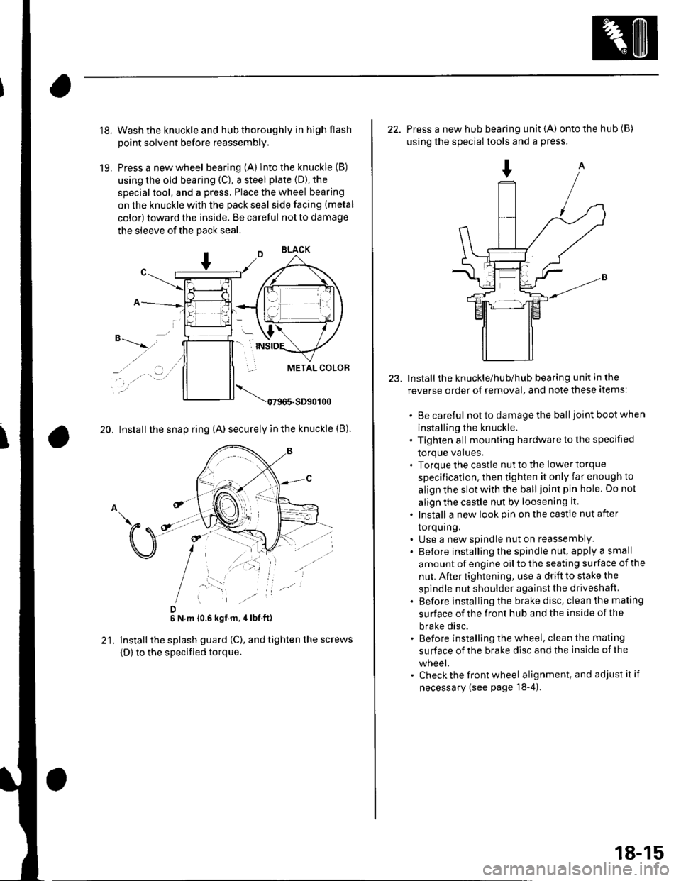
18.
19.
Wash the knuckle and hub thoroughly in hlgh flash
point solvent before reassembly.
Press a new wheel bearing (A) into the knuckle (B)
using the old bearing (C), a steel plate {D). the
special tool, and a press. Place the wheel bearing
on the knuckle with the pack seal side facing (metal
color) toward the inside. Be careful not to damage
the sleeve of the pack seal.
"-t-_"*,,''
_, .' . . a-�.) ../
..-.
20. Install the snap ring (A) securely in the knuckle (B).
D6 N.m 10.6 kgf.m,4lbf ft)
lnstall the splash guard (C), and tighten the screws
(D) to the specified torque.
23.
22. Press a new hub bearing unit {A) ontothehub(B)
using the special tools and a press.
Installthe knuckle/hub/hub bearing unit in the
reverse order of removal, and note these items:
. Be careful notto damagethe balljoint bootwhen
installing the knuckle.. Tighten all mounting hardware to the specified
lOrque values.. Torque the castle nut to the lower torque
specification, then tighten it only far enough to
align the slot with the ball joint pin hole. Do not
align the castle nut by loosening it.
. Install a new look pin on the castle nut after
torquing.. Use a new spindle nut on reassembly.. Before installing the spindle nut, apply a small
amount of engine oil to the seating surface of the
nut. After tightening, use a drift to stake the
spindle nut shoulder against the driveshaft.
. Before installlng the brake disc, clean the mating
surface of the front hub and the inside of the
brake disc.. Before installing the wheel, clean the mating
su rface of the brake disc and the inside of the
wneet.. Check the front wheel alignment, and adjust it if
necessary (see page 18-4).
18-15
Page 574 of 1139
Front Suspension
Ball Joint Boot Replacement
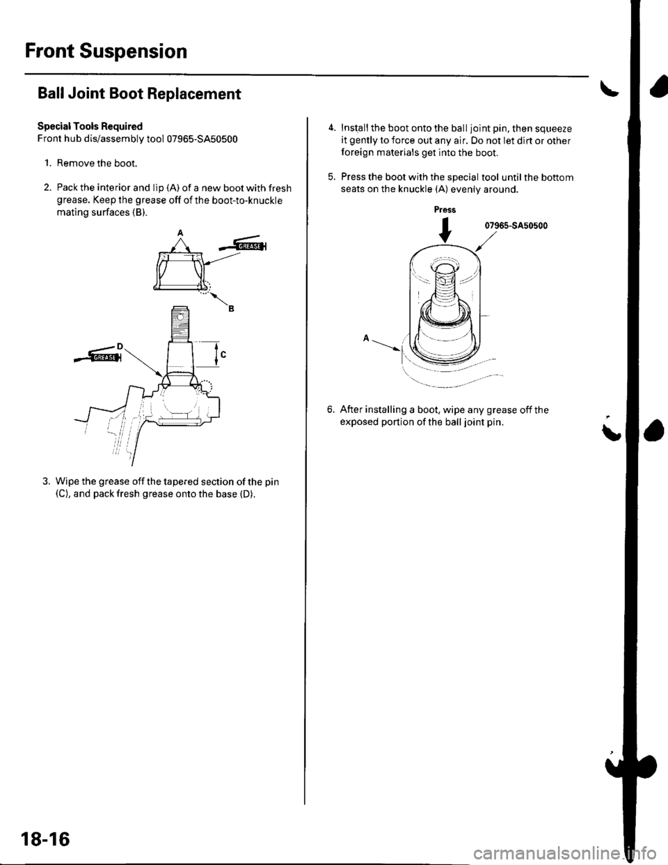
Special Tools Required
Front hub dis/assembly tool 07965-5450500
1. Remove the boot.
2. Pack the interior and lip (A) of a new boot with fresh
grease. Keep the grease off of the boot-to-knuckle
mating surfaces (B).
-6r
rffi
€l
--B
Wipe the grease off the tapered section of the pin
(C), and pack fresh grease onto the base (D).
tI
18-16
Inst€ll the boot onto the ball joint pin, then squeeze
it gently to force out any air. Do not let dlrt or other
foreign materials get into the boot.
Press the boot with the special tool until the bottom
seats on the knuckle (A) evenly around.
pross
07965-SA50500
6.After installing a boot, wipe any grease off the
exposed portion of the ball joint pin.
i
Page 577 of 1139
Lower Arm Removal/lnstallation
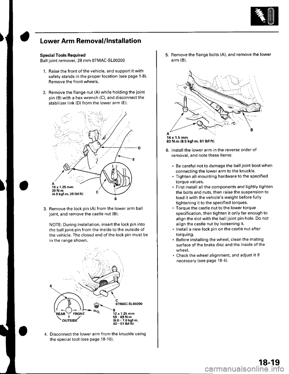
SpecialTools Required
Ball joint remover,2S mm 07|MAC-S100200
1. Raise the front of the vehicle, and support it with
safety stands in the proper location (see page 1-8).
Remove the front wheels.
Remove the flange nut (A) while holding the joint
pin {B) with a hex wrench (C), and disconnect the
stabilizer link (D)from the lower arm (E).
10 x 1.25 mm39 N.m{4.0 kgf m, 29 lbt.ft)
3.Remove the lock pin (A) from the lower arm ball
joint, and remove the castle nut (B).
NOTE: During installation, insertthe lock pin into
the ball joint pin from the inside to the outside of
the vehicle. The closed end of the lock pin must be
in the range shown.
6--__ oTMAc-sloo2oo
@a12 x 1.25 mm59 69Nm16.0-7.0 kgt-m,43 51 lbf.ft)
4.Disconnect the lower arm from the knuckle using
the special tool (see page 18-10).
5. Remove the flange bolts (A), and remove the lower
arm {B}.
14 x 1.5 mm83 N.m (8.5 kgf.m,61 lbf.ft)
6. Installthe lower arm in the reverse order of
removal, and note these items:
. Be careful not to damage the ball joint boot when
connecting the lower arm to the knuckle.
' Tighten all mounting hardware to the specified
torque values,. Firstinstall all the components and lightlytighten
the bolts and nuts. then raise the suspension to
load it with the vehicle's weight before fully
tightening it to the specified torques.. Torque the castle nut to the lower torque
specification, then tighten it only far enough to
align the slot with the ball joint pin hole. Do not
allgn the castle nut by loosening it.
. Install a new lock pin on the castle nut after
torquing.. Before installing the wheel, clean the mating
surface of the brake disc and the inside of the
wneet.. Check the wheel alignment, and adjustitif
necessary (see page '18-4).
18-19
Page 606 of 1139
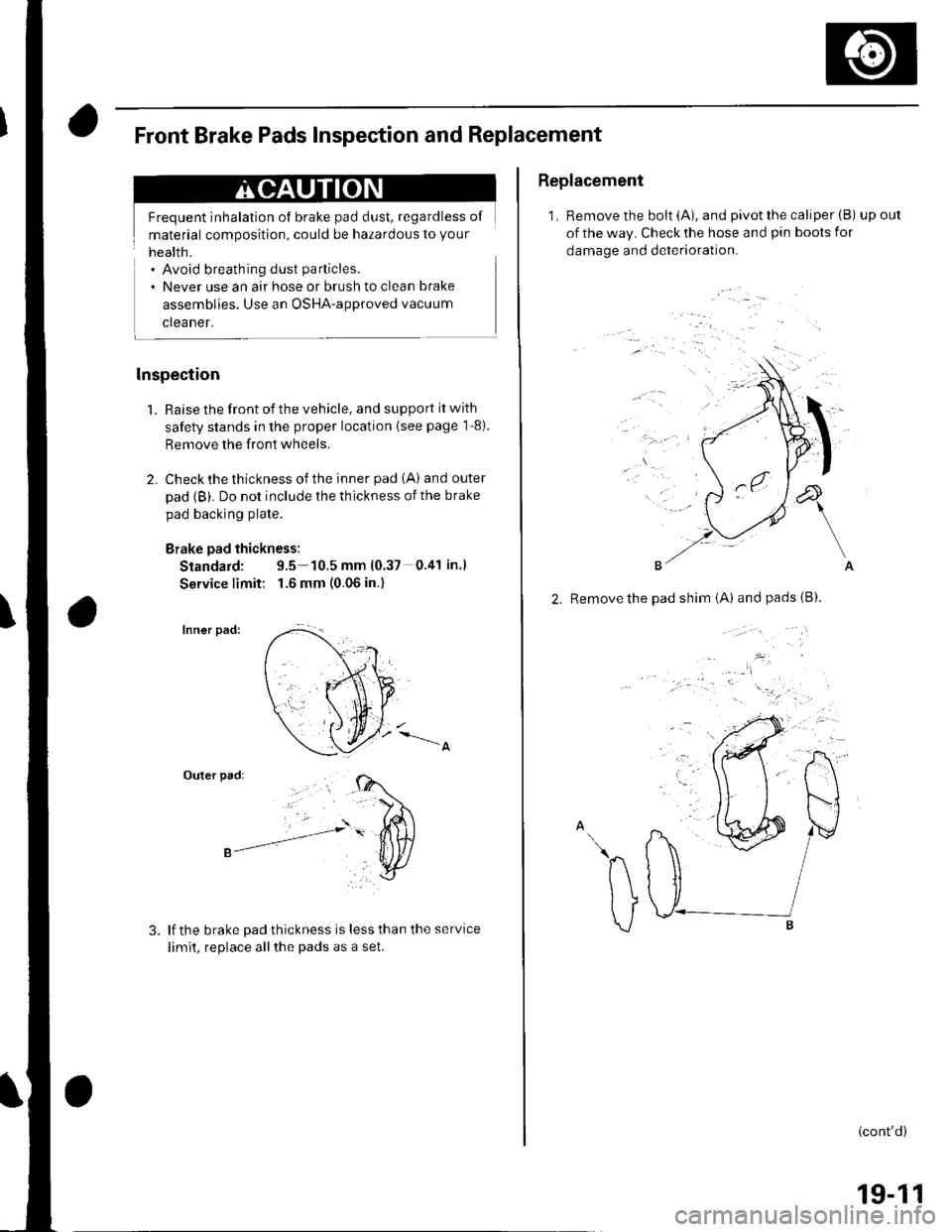
Frequent inhalation of brake pad dust, regardless of
material composition, could be hazardous to your
Front Brake Pads Inspection and Replacement
. Avoid breathing dust particles.
. Never use an air hose or brush to clean brake
assemblies. Use an OSHA-approved vacuum
cleaner.
lnspection
1. Raise the front of the vehicle, and support it with
safety stands in the proper location {see page 1'8).
Remove the front wheels.
2. Check the thickness of the inner pad iA) and outer
pad {B). Do not include the thickness of the brake
pad backing plate.
Brake pad thickness:
Standard: 9.5 10.5 mm (0.37 0.41 in.l
Service limit: 1.6 mm (0.06 in.)
Inner pad:
Outer pad:
lf the brake Dad thickness is less than the service
limit, replace allthe pads as a set.
Replacement
1. Remove the bolt (A), and pivot the caliper (B) upout
of the way. Check the hose and pin boots for
damage and deterioration.
'..'
, .a
&
\
A
2. Remove the pad shim iA) andpads{B).
.^h v/
\ tJ I
v ."r------B
(cont'd)
19-11
Page 607 of 1139
Conventional Brake Gomponents
Front Brake Pads Inspection and Replacement (cont'dl
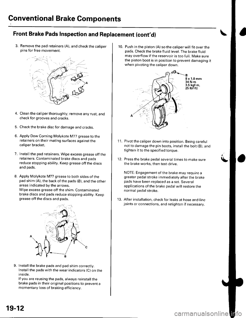
3. Remove the pad retainers (A), and check the caliperpins for free movement.
/:-."
t-... .,.';-iri.: '1=' r
.. a.-
4. Clean the caliper thoroughly; remove any rust, andcheck for grooves and cracks.
5. Checkthe brake disc for damage and cracks.
6. Apply Dow Corning Molykote M77 grease to theretainers on their mating surfaces against thecaliper bracket.
7. Installthe pad retainers. Wipe excess grease offtheretainers. Contaminated brake discs and pads
reduce stopping ability. Keep grease off the discsand pads.
8. Apply Molykote l\477 grease to both sides of thepad shim {A), the back ofthe pads (B), and the other
areas indicated by the arrows.
Wipe excess grease off the shim. Contaminated
brake discs and pads reduce stopping ability. Keepgrease off the discs and pads.
Installthe brake pads and pad shim correctly.Install the pads with the wear indicators (C) on theinside.
lf you are reusing the pads, always reinstall thebrake pads in their original positions to prevent amomentary loss of braking efficiency.
, a .).
19-12
10. Push in the piston (A) so the caliper will fitoverthepads. Check the brake fluid level. The brake fluid
may overflow if the reservoir is too full. lvlake surethe piston boot is in position to prevent damaging itwhen pivoting the caliper down
8x1.0mm34 N.m3.5 kgt m.25 tbf.ft)
11. Pivot the caliper down into position. Being carefulnot to damage the pin boots, install the bolt (B), and
tighten it to the specified torque.
12. Press the brake pedal several timestomakesure
the brake works, then test drive.
NOTE: Engagement of the brake may require agreater pedal stroke immediately after the brakepads have been replaced as a set. Several
applications of lhe brake pedal will restore thenormal pedal stroke.
13. After installation, check for leaks at hose and linejoants or connections, and retighten if necessary.
\