diagram HONDA CIVIC 2002 7.G Owner's Guide
[x] Cancel search | Manufacturer: HONDA, Model Year: 2002, Model line: CIVIC, Model: HONDA CIVIC 2002 7.GPages: 1139, PDF Size: 28.19 MB
Page 831 of 1139
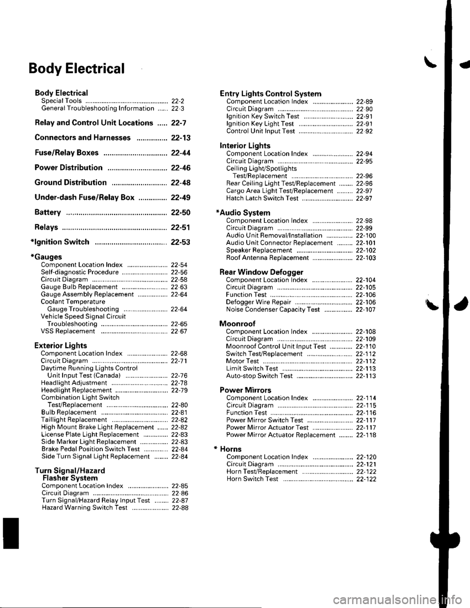
\Body Electrical
Body ElectricalSpecialToolsGeneral Troubleshooting tntorrnaiion.'......
Relay and Control Unit Locations .....
Connectors and Harnesses
Fuse/Relay Boxes ...............................
Power Distribution .............................
Ground Distribution ...........................
Under-dash Fuse/Relay Box ..............
Battery ..............
Relays ................
*lgnition Switch ..............
*Gauges
Component Location Index .......................Self-diagnostic Procedure ..........................Circuit DiagramGauge Bulb Replacement ..........................Gauge Assembly ReplacementCoolant Temperature
Gauge Troubleshooting .... ....................Vehicle Speed Signal CircuitTroubleshootingVSS Replacement
Exterior LightsComponent Location Index .......................Circuit DiagramDaytime Running Lights ControiUnit Input Test (Canada) ........................Headlight Ad,ustment .................. .. .....Headlighr Replacement ..............................Combination Light SwitchTest/ReplacementBulb ReplacementTaillight Replacement ..........................High Mount Brake Light Replacement ......License Plate Light Replacement ..............Side Marker Light Replacement ................Brake Pedal Position Switch Test ..............Side Turn Signal Light Replacement ........
Turn Signal/HazardFlasher SystemComponent Location Index .......................Circuit DiagramTurn Signal/Hazard Relay lnputTest ........Hazard Warning Switch Test
22,3
22-7
22-13
22-44
22-46
22-4A
22-49
22-50
22-51
22-53
22-5422-5622-5422 6322-64
22-64
22-6522 61
22-6822--71
22-7 622-7422-79
22-AO22-4122-8222-4222-4322-4322-4422-84
22-8�522 A622-8722-88
22-10422-105
22-10622-107
Entry Lights control systemComponent Location Index ....................... 22-89Circuit Diagram ......... 22 90lgnition Key Switch Test .....................,...... 22-9'llgnition Key Light Test ............................... 22-91Control Unit Input Test ..........,.................... 22 92
Interior LightsComponent Location Index ....................... 22-94Circuit Diagram ......... 22-95Ceiling LighVSpotlightsTesVReplacement ................................... 22-96Rear Ceiling Light TesVReplacem ent ........ 22-96Cargo Area Light Test/Replacem ent ......... 22-97Hatch Latch Switch Test ..,..,....................... 22-97
*Audio SystemComponent Location Index ....................... 22-98Circuit Diagram ......... 22,99Audio Unit Removal/lnstallation ............... 22-1OOAudio Unit Connector Replacement ......... 22-101Speaker Replacement ................................ 22-102Roof Antenna Rep1acement ....................-.. 22-103
Rear Window DefoggerComponent Location Index ...........Circuit Diasram .. ....... .. ..... ....... ...:::::.::.::.Function TestDefogger Wire Repair .................................Noise Condenser CapacityTest ................
MoonroofComponent Location Index ....................... 22-1OBCircuit Diagram ......... 22-109Moonroof Control Unit Input Test ............. 22-'l10Switch TesVReplacement ........,.....,........... 22-1 12Motor Test ................. 22-112Limit Swilch Test ...... 22-'l'13Auto-stop Switch Test ................................ 22-1 13
Power MirrorsComponent Location Index ....................... 22-114Circuit Diagram ......... 22-115Function Test ............. 22-116Power Mirror Switch Test .......................... 22-ll7Power Mirror Actuator Test ....................... 22-117Power Mirror Actuator Replacement ........ 22-11A
* HornsComponent Location Index ....................... 22-120Circuit Diagram ......... 22-121Horn TesVReplacement ...........................-. 22-122Horn Switch Test .,.... 22-122
\
Page 832 of 1139
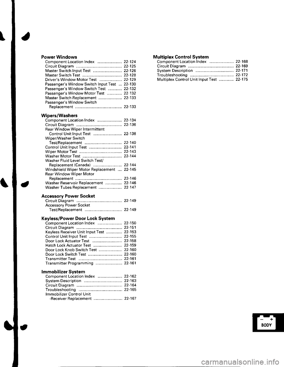
Power WindowsComponent Location Index ..........
circuit Diagram . .. ............... .........:.::::.::::.:Master Switch Input Test ...........................Master Switch TestDriver's Window Motor Test .....................
Passenger's Window Switch lnput Test ...Passenger's Window Switch Test .............
Passenger's Window Motor Test ..............
lMaster Switch Replacement ......................
Passenger's Window SwitchReplacement
Wipers/WashersComponent Location Index .......................
Circuit DiagramRear Window Wiper Intermiftent
Control Unit Input Test ...........................Wiper/Washer SwitchTesVReplacementControl Unit Input Test ...............................Wiper Motor Test
Washer Motor TestWasher Fluid Level Switch TesV
Replacement (Canadal ..........................
Windshield Wiper Motor Replacement ....
Rear Window Wiper MotorReplacementWasher Reservoir Replacement ................
Washer Tubes Beplacement ......................
Accessory Power SocketCircuit Diagram ......... 22-149
Accessory Power Socket
TesVReplacement ................................... 22-1 49
Keyless/Power Door Lock System
Component Location Index ....................... 22-150
Circuit Diagram ......... 22-151Keyless Receiver Unit InputTest ............... 22-153
Control Unit Input Test ............................... 22-155
Door LockActuatorTest .........,.......,..,.,..... 22-158Hatch LockActuatorTest ........................... 22-159
Door Lock Knob Switch Test ...................... 22-160
Door Lock Switch Test ................................ 22-160
Transmitter Test ....... 22-161
Transmitter Programming ......................... 22-161
Multiplex Control SystemComponent Location Index ...........
circuit Diagram ...... ........................::.:..:.::.:
Svstem DescriDtionTroubleshootingMultiolex Control Unit InDut Test .............
22 12422-12522-12622-12822-129
22- t30
22-13222 13222-133
22-133
22-134
22-138
22-14022-14122-14322-144
22-14422-145
22-14622-14622 147
22,16422-16922-17'l22,11222-175
lmmobilizer Systemcomponent Location Index ...........
System Description ....... ............. ..:..:..:.:...
Circuit DiagramTroubleshootinglmmobilizer Control Unit-Receiver Replacement ...........................
22-16222-16322-164
22-167
Page 889 of 1139
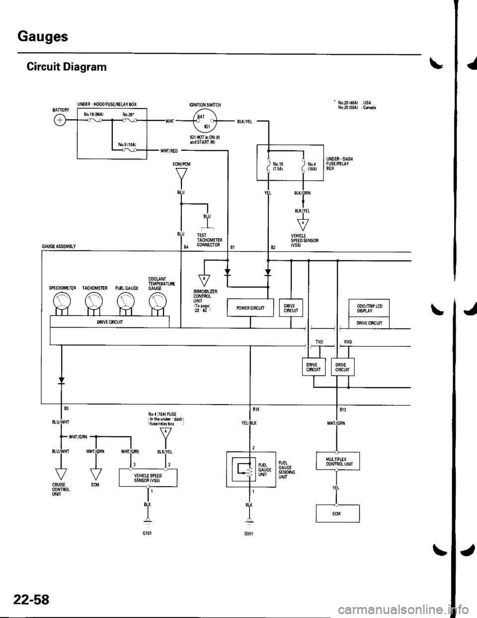
Gauges
Circuit Diagram
' No20ioAl :USA
ECM/PCM
V
I-r'
r--l
lJ,
I ii-ciorurnnI 8| coNNECron
Norll0AlFUSE
UflOEN fiOOO FUSE/8ILAY 8OX
COOLANITEMPfNAIUFTSPIEDOMEIEN TACHOMEIIR FUTLGAUGI GAUGE
8L(
-o-
22-58
Page 891 of 1139
J
a
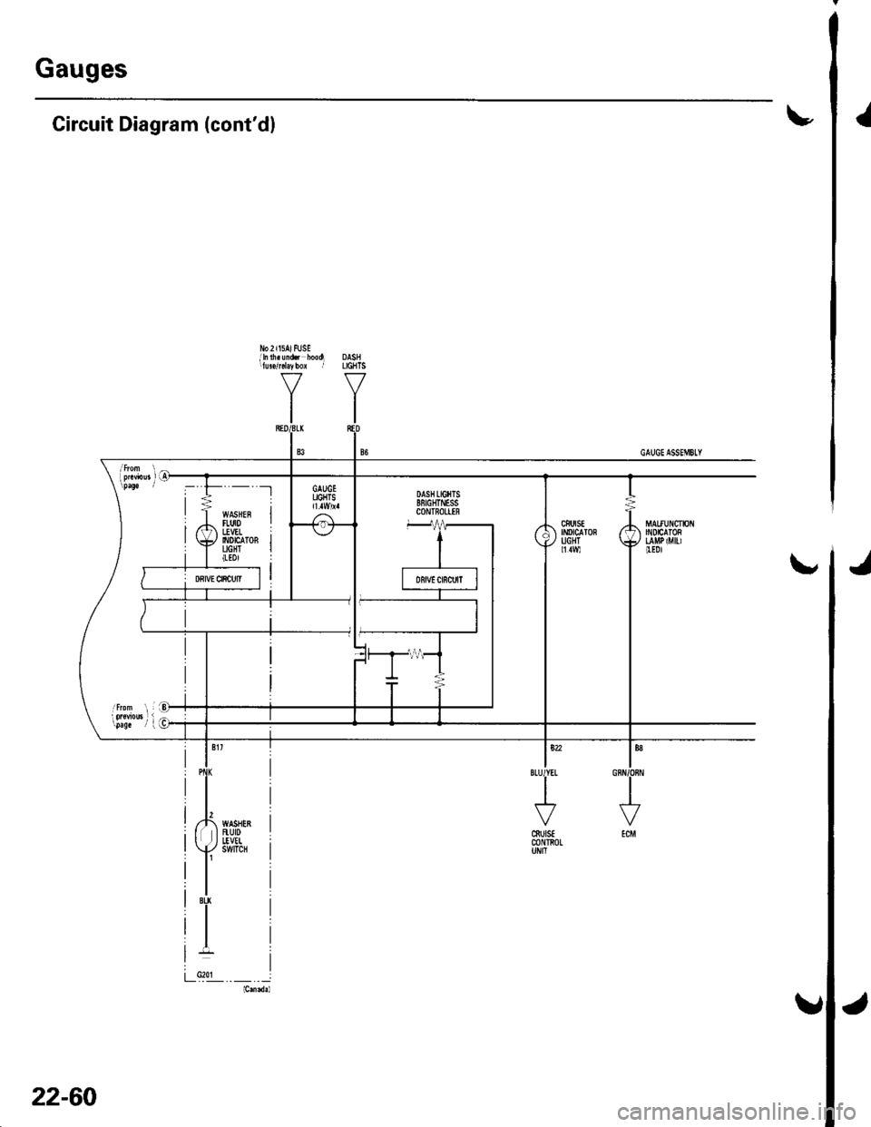
Gauges
I
No2il5AlFUSEilnlh.undi hooq DASHllu!./rcl.ybox r LGHTS
YY
tltl
Circuit Diagram (cont'dl
ls?2IBLUIYEL
I
J
cSutsEm n0L
'- -t
WASHEFItut0I!VEL6t0tc ToRUGHT(tDl
22-60
Page 893 of 1139
Gauges
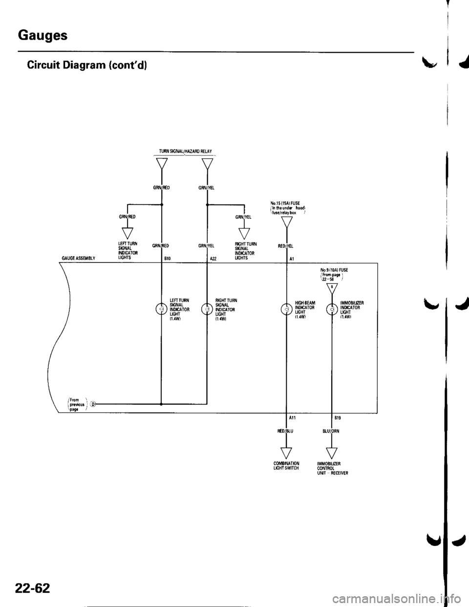
\"Circuit Diagram (cont'dl
CoME|NAT|ON tMf,tOBtUZEnLtctlTswtTclt @l TRoLUN|I ftCtIVER
GRNIfiED
I\""'7
VLEFTTUNSIGI'IALII'{DICATORGAUGIASSEi|BLY LTCHTS
\,HIGHSEAM -|. IMMOBITIZERltDtcATon r/: tilucaToB
f,il vll9i,]
22-62
J
Page 903 of 1139
J
J
Exterior Lights
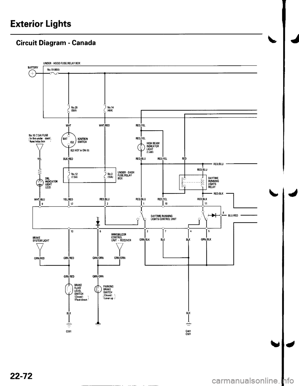
tCircuit Diagram - Canada
t
cl.1G501G301
UNOEN HOOO FUSE/8ELAY BOX
No l9l80Al
J
) to.o- i50AlNo.1'lloa)
No.!0(7 SAlr
V
I'l'
I
usE /',d.3hl I EAr
\
BU1
IT WHT
t-\
rc|'/moN. rcz/ swfrcH
v
I G2 Hor in 0N {ll)
IBED
ED RED,I
I'2
I*01
I
fifi li{*1l,.H'� I
I
ItU RED/,l
-_l
-- ,'orrro". ) INDICAIOF-/ l'lcli;
BLUl
RE=.|
A DNL) No12i l7.5AlDAYTIMEBUNNINCLIGHTSEfLAY\y
IIHT/BIIn
TIGHTluDl
12REt0t1
--t
lT
,{ oorr,",rr.,ro { r-
I I
uctrrscournoLu,'r"
J l
SLU/BID8
SYSIIM UGHI
VYIGNfl/FEO GRI\
(
!3
/NED
II
I
f'r 88A(EI FiUrD2 , LTVEL[./ SWITCH
I
'nddoM
I
i
||MoS|UZEnCONTNOLUNIT RECEIVEB
17
YI
3
BI( BIBIG8N
F PANKNG; } BNAXE+./ swrTcH
i
J\,
22-72
Page 905 of 1139
Exterior Lights
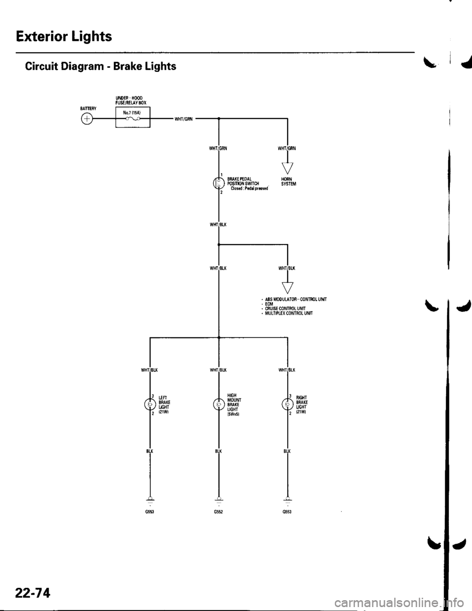
\Circuit Diagram - Brake Lights
UiDEN HOODFUSE/NEUYBOXSATIISYI r!o7l15A) | ,r-T-v--rrni'citr
22-7 4
Page 906 of 1139
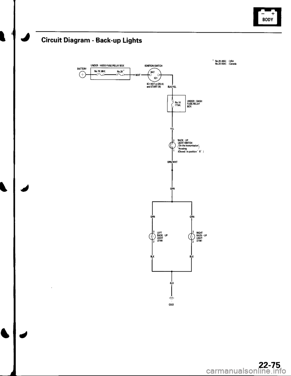
Circuit Diagram - Back-up Lights
UiDEN H@D FUSI/8EIAY 80)(
22-75
Page 917 of 1139
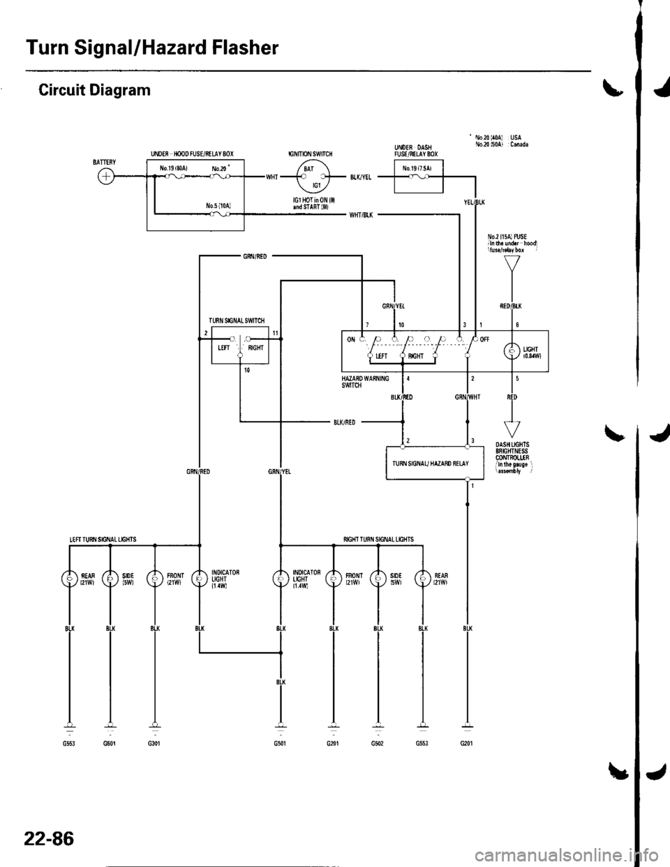
Turn Signal/Hazard Flasher
UNDff HOOD FUSUftIIY 8OX
Circuit Diagram\
'No20lr0A USAUt oEB DASH No.2{ l50A) :CmadaTUSVRILAY 8OX
J
INDICATONIIGHT11.1W)
fiIGHT T
FBONT
22-86
!
Page 921 of 1139
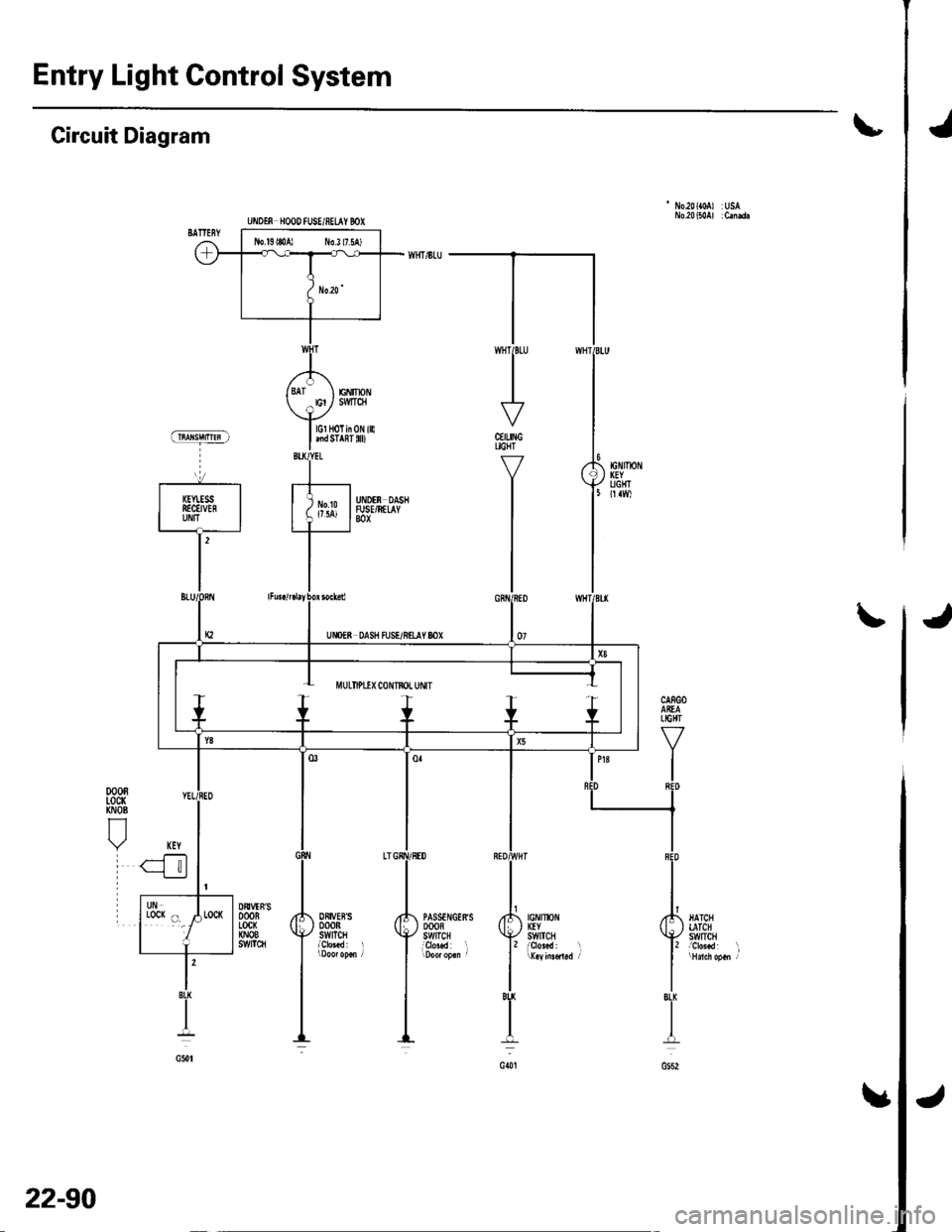
Entry Light Control System
Jt
'No.20({0A) USA
Circuit Diagram
CEILINGUGHT
Y
I
I
J\
jIGNIlx)NKEYSWtTCH
PASSTNGERSDOOBSWITCHi9r"..d l
ORIVEBSDOORSWITCH
DtrVTN'SDOORLocx(NOBs!t/tTc8
l'BU
I
G()t
lGl HoTin 0N illlnd STAnT 0D
EiIIpNSMTqI
UiIOTf, HOOD fUSE/8ELAY BOX
J
22-90