HONDA CIVIC 2002 7.G Service Manual
CIVIC 2002 7.G
HONDA
HONDA
https://www.carmanualsonline.info/img/13/5744/w960_5744-0.png
HONDA CIVIC 2002 7.G Service Manual
Page 922 of 1139
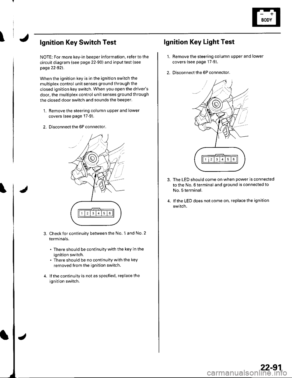
\lgnition Key Switch Test
NOTE: For more key-in beeper information, refer to the
circuit diagram (see page 22-90) and input test (see
page 22-921.
When the ignition key is in the ignition switch the
multiplex control unit senses ground through the
closed ignition key switch. When you open the driver's
door, the multiplex control unit senses ground through
the closed door switch and sounds the beeper.
1. Remove the steering column upper and lower
covers (see page'17-9).
2. Disconnect the 6P connector.
3.Check for continuity between the No. 1 and No. 2
termrnars.
. There should be continuity with the key in the
ignition switch.. There should be no continuity with the key
removed from the ignition switch.
lf the continuity is not as specfied, replace the
ignition switch.
lgnition Key Light Test
1.Remove the steering column upper and lower
covers (see page 17-9).
Disconnect the 6P connector,
The LED should come on when power is connected
to the No. 6 terminal and ground is connected to
No. 5 terminal.
lf the LED does not come on, replace the ignition
swrtch.
i'
/.'
22-91
Page 926 of 1139
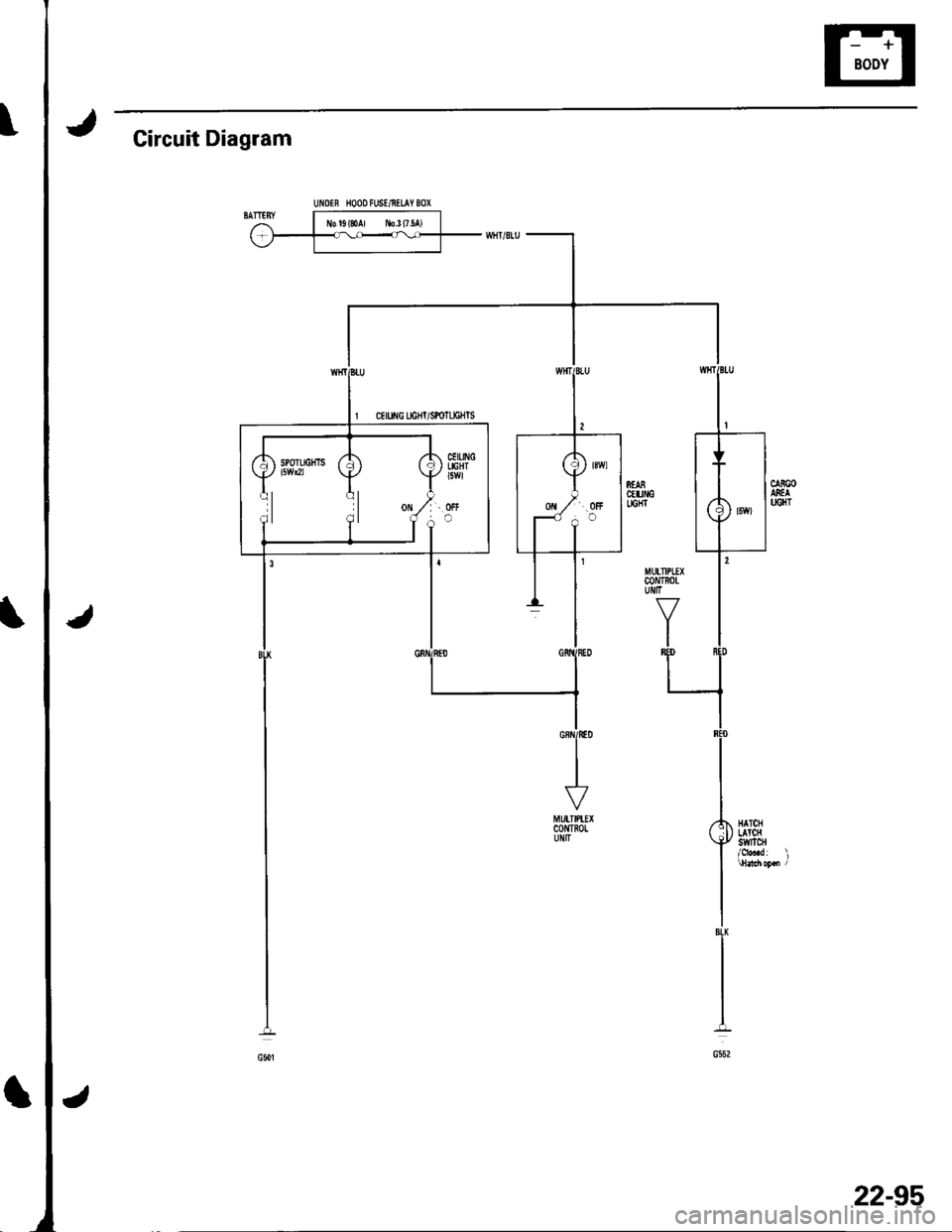
Circuit Diagram
STABctu[GLIGHT
MUITIPLEXc0NTlotUIIIT
J\
HATCHLATClIswtTcH
22-95
Page 930 of 1139
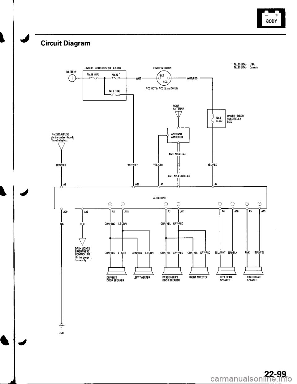
tCircuit Diagram
' No.20ioA) :USA
/ 8AT \--------F f!t- WHT/FED ACC /
ACC HoTinACC lllmd0N llll
AUDIO UflIT
t-ra-r:-raOe?a
DRIVER'SDOORSPEArcFIEFITWEETERPASSE!{GIF'S SIGIITTWEETEBDOOB SPEAKESLEFTFEAB NrcBTREAFSPEA(I8 SPEAKEF
22-99
Page 936 of 1139
t
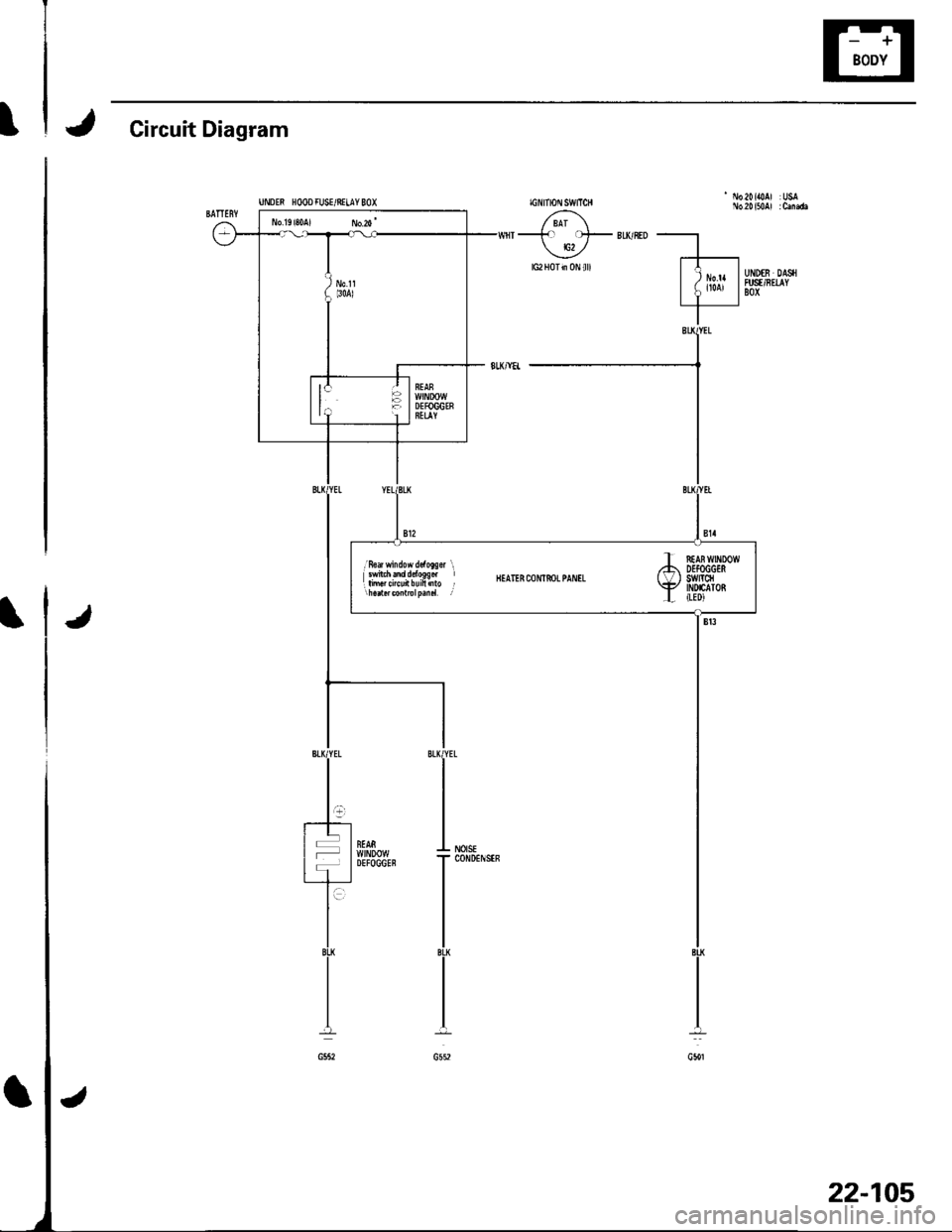
J Circuit Diagram
J
;Hl}lj.'fl,1fl1fi" BEATERcoNrf,oLpANrL
T f,rAi wrxDow,74 DEfOGGES( \/ I SWrcfl\iP INDIATORL ILEDI
22-105
Page 940 of 1139
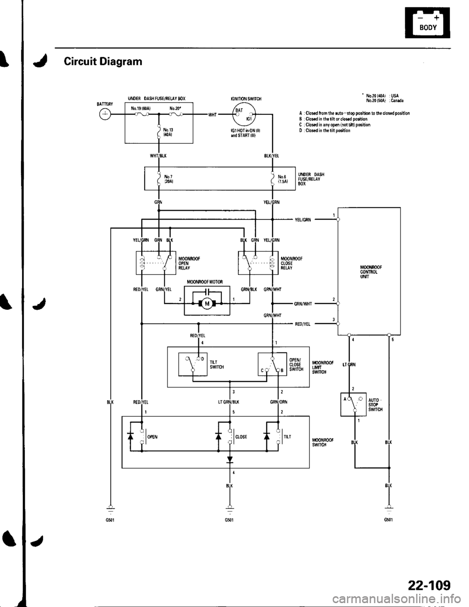
Circuit Diagram
- No.20lOAl :USNo.20150 ) :Canda
A Clos.d fom lh€ ruto nop poshio. to lh€ doed porhionB Clo!.d in th€ lilt or do3.d poilionC : Clo!.d in any op.n (io! riltl posirionD Clos.d in th€ tilt po6iiion
UNDIR OAS8 FUSE/NILAY MX
BL|(
+
G50t
8LI
I
G5{1
22-109
Page 946 of 1139
Circuit Diagram
UiIDTS rcOD R]SE/R€LAY 8OXrcilmoN s1/vtTcH
'1 ih.a i|0At :UsaUiD$ DASHN'SUnIIAY 8OX
Jt
22-115
Page 952 of 1139
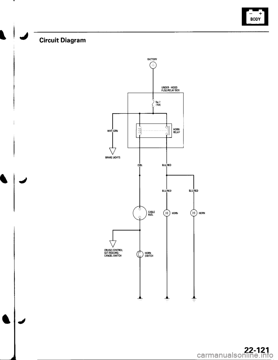
JGircuit Diagram
J
22-121
Page 956 of 1139
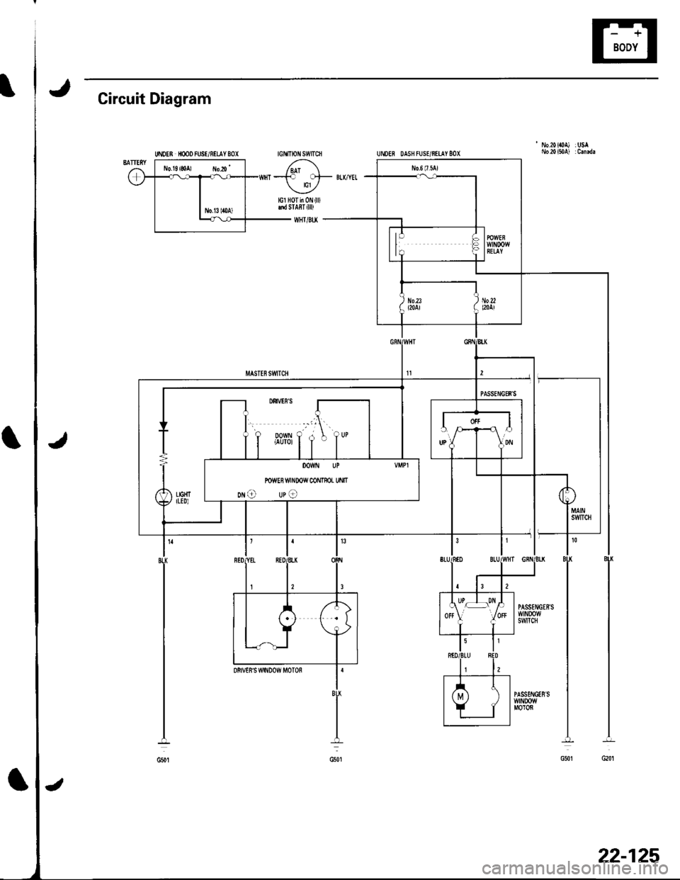
Circuit Diagram
tGt' Ttoit swtTcfi
'No.20il0A) : USAUNOER HMO FUSI/8tLAY 8OI
--+r o'F BTTYEL
U/lGl HOT in 0N {ll)tnd STABT {llll
WHT/BU
22-125
Page 967 of 1139
Wipers/Washers
Circuit Diagram - Windshield
UNOEN HOOD FL]SE/8ELAY BOX IGNITIONSWITCN'7{ F;^--il I 6\
U-I^-- -':-;--u,Hr-
o,f-''*""
\1
L\'
MULTIPIIXcoiln0LUNIT
22-136
\,!
Page 968 of 1139
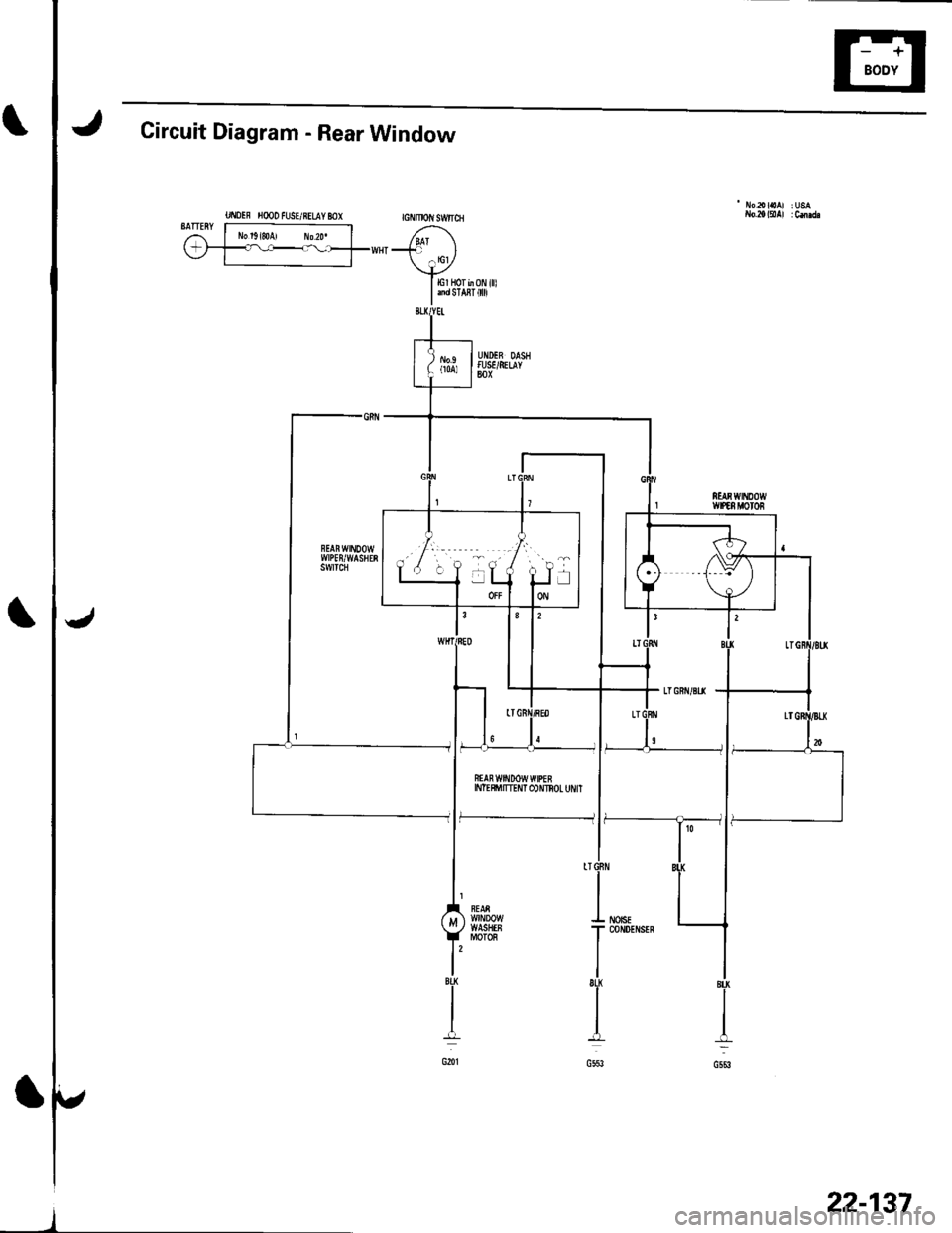
Circuit Diagram - Rear Window
UI\IOIF H@O FUSE/RELAY MX GNMOIIISW|ICH
- No2olaoAl :USA
BATTERY r----------------;i l No'g,soA, ro2o. | /,^1\(-;1_=l----_--_fww{"-' l
\+ylErHorb0Ni||l
I andsra8r 0
ffAn w$tDow wtPEEINTE$'ITTEI'IT C{)NNOL UI'/IT
f--------------- li
22-137

![HONDA CIVIC 2002 7.G Service Manual Circuit Diagram
UiIDTS rcOD R]SE/R€LAY 8OXrcilmoN s1/vtTcH
1 ih.a i|0At :UsaUiD$ DASHNSUnIIAY 8OX
Jt
22-115 HONDA CIVIC 2002 7.G Service Manual Circuit Diagram
UiIDTS rcOD R]SE/R€LAY 8OXrcilmoN s1/vtTcH
1 ih.a i|0At :UsaUiD$ DASHNSUnIIAY 8OX
Jt
22-115](/img/13/5744/w960_5744-945.png)
![HONDA CIVIC 2002 7.G Service Manual Wipers/Washers
Circuit Diagram - Windshield
UNOEN HOOD FL]SE/8ELAY BOX IGNITIONSWITCN7{ F;^--il I 6\
U-I^-- -:-;--u,Hr-
o,f-*""
\1
L\
MULTIPIIXcoiln0LUNIT
22-136
\,! HONDA CIVIC 2002 7.G Service Manual Wipers/Washers
Circuit Diagram - Windshield
UNOEN HOOD FL]SE/8ELAY BOX IGNITIONSWITCN7{ F;^--il I 6\
U-I^-- -:-;--u,Hr-
o,f-*""
\1
L\
MULTIPIIXcoiln0LUNIT
22-136
\,!](/img/13/5744/w960_5744-966.png)
