diagram HONDA CIVIC 2002 7.G Repair Manual
[x] Cancel search | Manufacturer: HONDA, Model Year: 2002, Model line: CIVIC, Model: HONDA CIVIC 2002 7.GPages: 1139, PDF Size: 28.19 MB
Page 980 of 1139
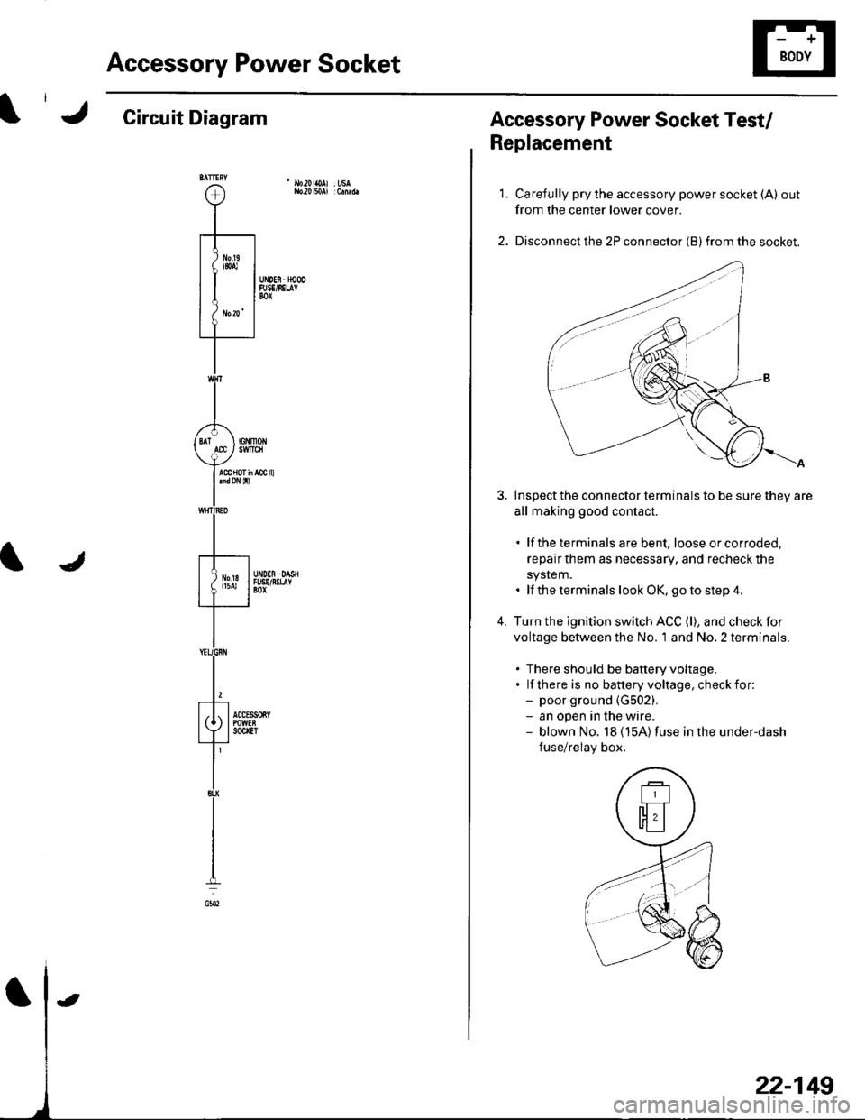
Accessory Power Socket
Circuit Diagram
22-149
Accessory Power Socket Test/
Replacement
1.
4.
Carefully pry the accessory power socket (A) out
from the center lower cover.
Disconnect the 2P connector (B) from the socket.
Inspect the connector terminals to be sure they are
all making good contact.
. lf the terminals are bent, loose orcorroded,
repairthem as necessary, and recheck the
system.. lf the terminals look OK, go to step 4.
Turn the ignition switch ACC (l), and check for
voltage between the No. 'l and No. 2 terminals.
. There should be battery voltage.. lf there is no banery voltage, checkfor:- poor ground {G502).- an open in the wire.- blown No. 18 (15A)fuse in the under-dash
fuse/relay box.
Page 982 of 1139
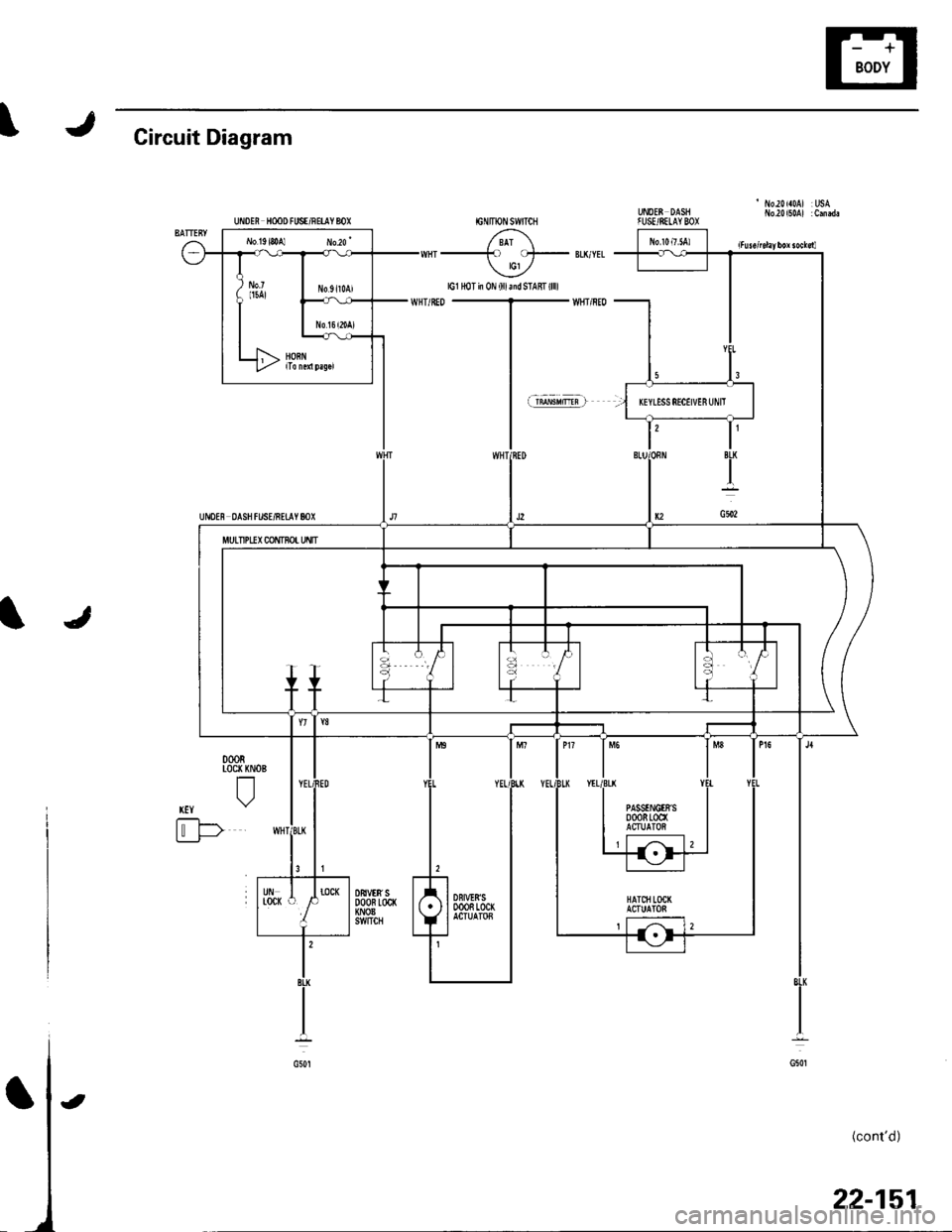
J\Circuit Diagram
UNOEE DASHfUSE/SELAYBOXUiDEN HooD FUSE/RETIY 8OX
UI'IDE8 DASH f USE/RETAY 80X
/ 8Ar \-) cl- lG1 ,/
lG1 HoT in 0N (lllaidSTAfft(llll
JI
000RLoc( KNOE
tl
xtY \"2
t'-F>Li___J-
(cont'd)
22-151
l3
IT
IBLK
I
G502
MULTIPUX CONTNo! Uflfi
PASSTNGtrS0008100(ACTUATOi
DBt!'t8'�S000R 100(ACTUATOB
t
Page 983 of 1139
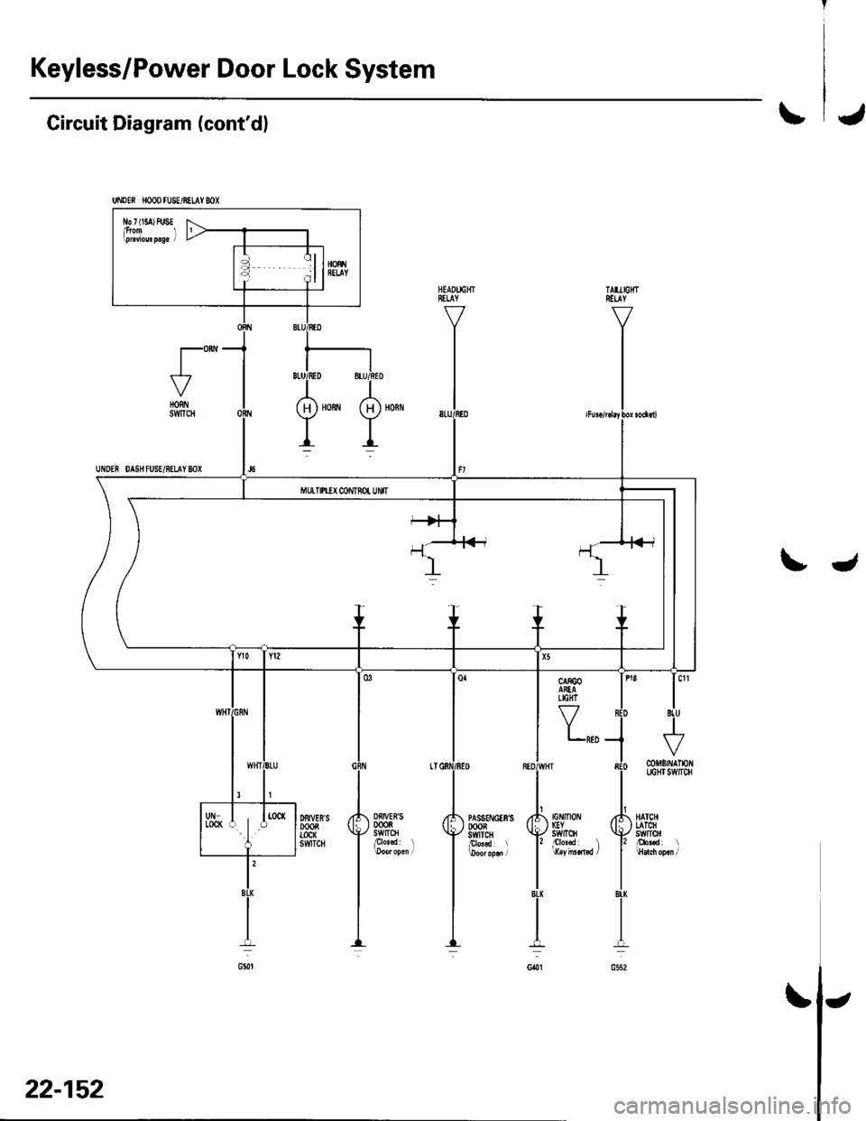
Keyless/Power Door Lock System
UNDEN HOOD FU8E/BELAY MX
l\b r t15a) FUSE
Circuit Diagram (cont'dl\J
t"-HORNSWTCH
UNDEN DAS}I FUSE/8ELAY 8OX
tJ
Y,,,
Df,IVEB'S0008swtrcHplo'.d l
DFIVES'SDOOBTOCK6WTCH
tG tltot IGYstvrTcH
mMErNAlloflLIGHI SWITCH
HATCHLATCHswlrol
22-152
\
Page 995 of 1139
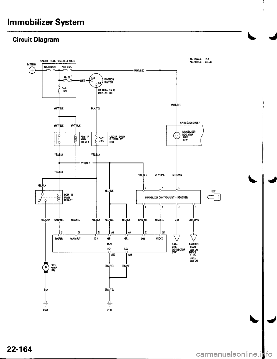
lmmobilizer System
J
I
UNDTR rcOD FUSE/RELAY 8OX
rGNtTt0i/swlrcH
lct HoT in 0N {ll).nd SIAnT l|l)
0R8 itAWStY tct tGPl tGPz LG3 |M0CD
EC
LGI LG2
t
' No20(LAl r USA
Circuit Diagram
FGN
8ELAY1
YEUBIJ(
t
DATA . PA8(II'IGLIN( SMIGCONNECIOR SWITCH{0Lcl .8nA{EFTUIDI!VELSWTfi
22-164
\J
Page 1000 of 1139

ICircuit Diagram
' I'10.20 {a0AJ :usAib.a)l50A) :C.nd.IGNITiON SWITCH
/ BAI \--_to oJ- BLI,'YEL tcl ./
J
G201
HAICIILATCHSWITCH
{cont'd)
UiIDM HOOD IUSE/NEUY BOX
MULTIPLEXc0NT80rtNsPECTror!CONNECIOF
UNDEf, DASHFUSE/NEUYBOX
22-169
Page 1001 of 1139
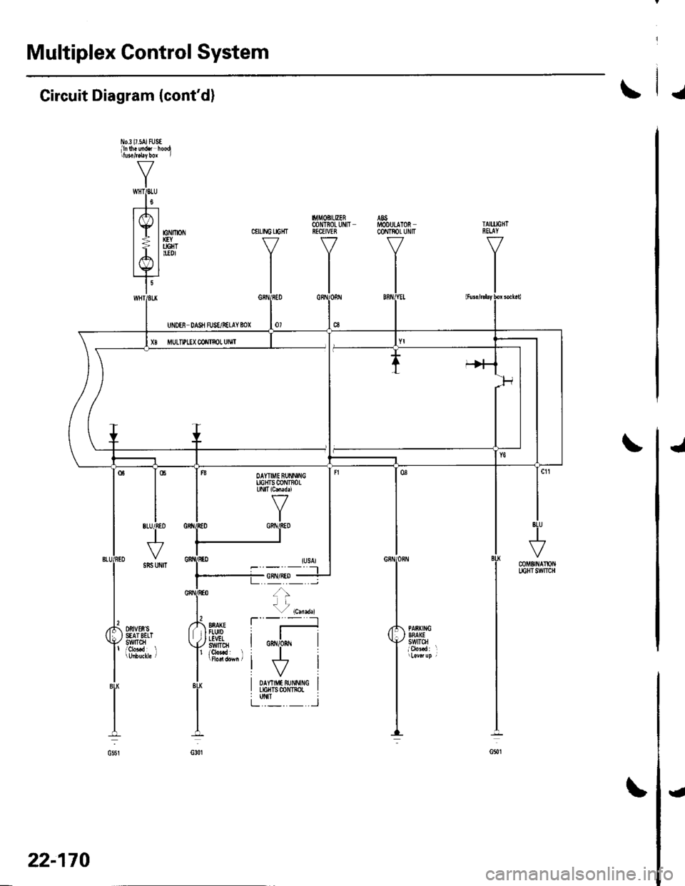
Multiplex Control System
J
J
Circuit Diagram (cont'd)
l'1o.3 l7.5AJ tUStlln$.uidt hoodritutefd4bor I
V
IwHTPLU
l0t--t---
lrfl |
lE lnv*-| > | ucHT
lA l'*'tYl
I'
CIILING LIGHT
I.l|MOBItEER@NTIOL UIIITRECEIVEE
VI
I
22-170
{
Page 1009 of 1139
I
I
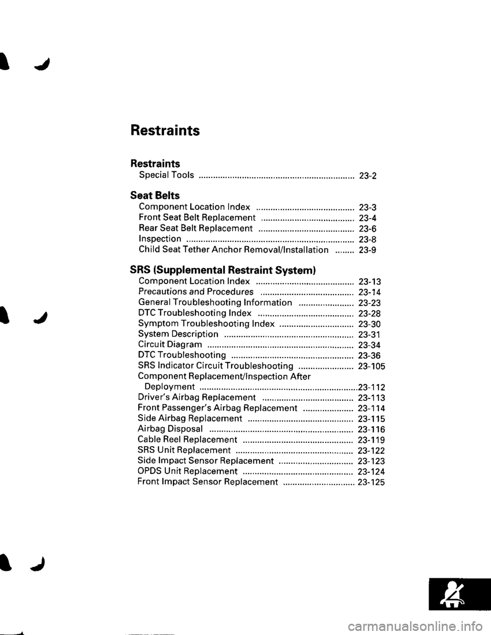
Restraints
Restraints
Special Tools ............. 23-2
Seat Belts
Component Location Index ......................................... 23-3
Front Seat Belt Replacement ....................................... 23-4
Rear Seat Belt Replacement ........................................ 23-6
Inspection .................. 23-8
Child Seat Tether Anchor Removal/lnstallation ........ 23-9
SRS (Supplemental Restraint Systeml
Component Location Index ......................................... 23-13
Precautions and Procedures ,,.,......... 23-14
General Troubleshooting Information ....................... 23-23
DTC Troubleshooting Index .............. 23-28
Symptom Troubleshooting Index ............................... 23-30
System Description ................. ........... 23-31
Circuit Diagram ......... 23-34
DTC Troubleshooting ............... .......... 23-36
SRS Indicator Circuit Troubleshooting ....................... 23-105
Component R e place me n(/ln s pect io n After
Deployment ..............23-112
Driver's Airbag Replacement ............ 23-113
Front Passenger's Airbag Replacement ..................... 23-1 14
Side Airbag Replacement .................. 23-115
Airbag Disposal ....................... ........... 23-116
Cable Reel Replacement .................... 23-119
SRS Unit Repfacement ....................... 23-122
Side fmpact Sensor Replacement ..........,.................... 23-123
OPDS Unit Replacement .................... 23-124
Front fmpact Sensor Replacement .............................. 23-125
Page 1041 of 1139
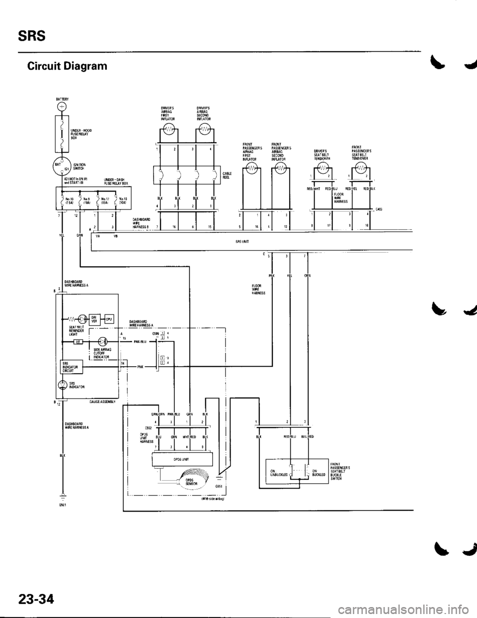
SRS
Circuit Diagram
rrssf c ssrarsftrrrl$0[n
J
4
i___':--_:"1
r-----Tr-i
23-34
\J
Page 1133 of 1139
Service Manual lndex
)s
NOTE: Referto the lollowing listto look up A/C Pressure Switch CircuitDTCS, symptoms, fuses, connectors, wire Troubleshooting ......... ...-.-....-...-.-.-....-..21-32 Bharnesses, specifications, maintenanceschedules, and general serviceinlormation:
DTC Troubleshooting Indexes
A/C Signal CircuitTroubleshooting.........................-...... 11-'133 Back-up Light SwitchTest .......................................................... 13'3A/F lAir Fuel Ratiol SensorABS/TCS Components ........................ 19-34 Replacement ....................................... 1 1-113 Back-up Li9ht3EPS Components ................................. '17-22 Circuit DiagramFueland Emissions11-i A-Dillar Corner Trim
ABS Indicator Circuit
Heating/Ventilation ................................ 21-9 Replacement ...............-.....-..............-.... 20,96 Ball Joint BootssRS ........................................................ 23-28Replacement ......
... 19-52 Ball Joints
22-75
18 16
Remova1.............-.......... . ...........18-10Symptom Troubleshooting Indexes TroubleshootingABS/TCSComponents........................ 19 35Cruise Control System ..........................4 38 ABS Modulator-contml UnitEPS Components ................................. 17-23 Bemoval/lnstallation ............................ 19-57 BettervFan Controls10,12
Accessory Powor Socket Front
Blowor Pow€r Transistor
.......22 50
Blower UnitRemoval/lnstallation ............................ 21-39
Fuel and Em issions .............................. 11-10 ABS/TCS ComoonentsHeating/Ventilation..............................21 10 Component Location Index ................. 19-30 Beverage Holder
SRS ........................................................ 23'30 CircuitDiaqram.......................... 19'42Blower MotorReplacement .....21 41
21-38
Power 0istribution ...............................22-46 TesVReplacement .............................. 22'149Under-dash Fuse/Relay Box ............... 22 45Under-hood Fuse/Belay Box ...............22 44 Accessory Power Sockets
Fuse/Relay lndexes
(to harness)
Connector and Wire Harness lndexesComponent Connectors
Circuit Oiagram .................................. 22-149
Air Cleaner......2214 Rep1acemen1.....................................11-162
Air MixControl MotorMeintenence section .................... Section 3 Replacement ......................................... 21'34 Brake CelipersTest......................21-34 Overhaul19-14,23Gene.al lnlormation section........ Section 1
21.57
Airbag. Driver's
Ahernator FR Signal CircuitTroubleshooting .... .........-..........11 134
AntennaReplacement
Inspection ............................................. 19-24Rep|acement................. .................... 19-25
Bieke Meder Cylinder
Irake Discs
A
Replacement ....................................... 23 1 'l3 Inspection .................... ................... 19-13,22Repair ...........-...................................... 23 1 16Brake Fluid Level SwitchAirbag. Front Passenger's TestBeplacement....................................... 23-1 14AIC Brake LightsComponent Location fndex ...................21-3 Altemator CircuitDiagram....................................22-74Description.....................................-....21'1'l Beplacement ................ ........................... 4 29CircuitDiagram....................................21-14 Overhaul .................................................4-30 Brake Lines and Hoses
19.10
A/C CompressolReplacement .......-...-............................. 21 -41
A/C Compr€ssor ClulchRep1acement......................................... 19-15.........22-103 Inspection ............................................. 19-16Inspecton........Overhaul ..........
A/C CondenserReplacement,.,
21-442l-49 Audio Unit
Replacement
Brake PadsRemoval/lnstallation .. ........................22-100 Inspection/Rep1acement................ 19-11,20A/C Compressor Clutch CircuitTroubleshooting ................................... 21-30 Audio Unit Connector Brake Pedal22101 Adjustment..............19,6ArfC Comoressor Relief ValvcReplacement ..........-...-.......................... 21-51 Audio/Entertainment
A/C Compr$sor Thermal Protector Circuit DiagramReplacement............-............................ 21-51
Component Location In dex .................22-9A Test .......-.............. 22-84Breke Pedal Posilion Switch
Brake Pedal Position Switch Signal Clrcuit11-137
.....21 52
A/C Condenser Fan CircuitTroubleshooting ................... . . . . . .....21-28
)s
Troubleshooting
(cont'd)
Page 1134 of 1139
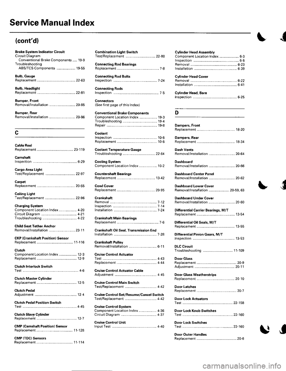
Service Manual Index
(cont'dl
Brake System Indicator CircuitCircuit DiagramConventional Brake Components..... 19-9TroubleshootingABS/TCS Components .... ....... ...... 19-55
Bulb, GeugeRep|acemenl................ .. ............2263
Bulb, HeadlightReplacement ......................................... 22-A1
Bumper, FrontRemoval/1nsra11ation ............................ 20 85
Bumper, RearRemoval/lnstallation... ... . .....20.86
Combination Light SwilchTesVReplacement ..............................22 80
Connecting Rod BearingsRep|acement...................... .......-....7-8
Connecting Rod Boltsf nspection ....................-.-.-.-.................... 7 -24
Connecting RodsInspection ........,,.,.,...,.,.,.,.,,,,.,,,.,.,.,.,.,.,.,.. 7 5
Connectors(See first page of this Index)
Conventional Brake Component3Component Location Index ................... 19'3Troub1eshootin9 ..................................... 19-4
Cylinder Head AssemblyComponent Location Index ..................... 6-3Inspection ................................................. 6 6Removal ..........&�23Insta11alion .............................................. 6 39
Cylinder Head Cover8emova1 ..............-.-................................. 6-22Installation ..............................................6-41
Cylinder Head, BareInspecton..,.....,.
D
c
Cable ReelReplacement....................................... 23-1 19
CamshaftInspection .......................-...-................... 6-29
Cargo Area LightTesVRep1acement ................................ 22-97
CarpetReplacement.....-...-..... ... ......-.20-55
Ceiling Light-estrReplacement ................................ 22.96
Charging SystemComponent Location Index................... 4-20Circuit Diagram ...................................... 4-21
19-8
CoolantInspection .................. ..... .. 106Replacement................. ... . .. 10 6
Coolant Temperature Gat|geTroub1eshootin9................................... 22 64
Cooling SyslemComponent Location Index................... 10-2
Countershaft BearingsReplacement............... ..................... 13-42
Cowl CoverReplacement............... .. ..... ....20-95
CrankshaftRemoval .................................................. 7 -12
Repair ..................
Inspec(on,,,,,........1 14
Dampers. FrontReplacement................ ..................... 18 20
Oampers, RearRep1acement......................................... 18-34
Dash VentsBemoval/lnstallation .-.......................... 20-64
DashboardBemoval/1nsta11ation ............................ 20-66
Oashboard Center PanelRemoval/1nstaf 1ation ............................ 20 62
Dashboard Lower CoverRemoval/lnstallation ...................... 20-59, 63
Dashboard Under CoverRemoval/lnstallation ............................ 20 60
Diff erential Carrier Bearings, M/TRep1acement,,......,...,...,.,.,,,.,.,,,........,.,. 13-54
Ditferential Oil Seals, M/T8ep1acement......................................... 13-55
Differential Pinion Gears, M/TInspection .,....-,.,,,.,..,.-,.,.........,.,.,,, 13 53
OLC CircuitTroubleshooting ................................ 1 1-109
Door GlassRep1acement.,.,,,,,,,,,,,.,,,,,,,,,,.,.,.,.,.,,,,,,.,, 20-9Adjustment. .. .....................20-11
Door Glass WeathelstripsReplacement .............-.. . . . ..........-......20 10
Door LatchesReplacement ..........-.-.............................. 20-7
Door Lock ActuatorsTest ...................................................... 22-154
Door Lock Knob SwitchesTest -......... . . . - . . . . . . . . ......22-160
Door Lock SwitchesTest ........... ............................ ............. 22-160
Door Outer HandlesRep1acemen1 ........................................... 20-6
3
Child Seat Tether AnchorRemoval/lnstaf lat;on .. ........................ 23 11
CKP (Crankshaft Position) SonsorReplacement....................................... 1 1-116
ClutchComponentLocation 1ndex................... 12-3Rep1acemen1........................................... 12-9
Clutch InteYlock SwitchTest.....-........-...-............. ...---.-.......4-6
Clutch Master CylinderReplacement........................................... 12 5
clutch PedalAdjustment ............................................. 12 4
Clutch Pedal Position SwitchTest.,.,,,,,.,,,.,.,,,,,,.,.,,,,,,,,,.,,,,,.. ......445
lnstallation.................. . ..... .....1-24
Crankshalt Main BearingsReplacement........-.-.................................. 7-6
CrankshaftOil Seal,Transmission End1nstanation .............................................. 7 28
Crankshafl PulleyRemoval/lnstallation -..................-.......... 6-1 1
Cruise Control Actuator
Troubleshooting
Clutch Slave CylindorBeplacemeit...
...................... 4-43
.......4-22
Test
12-1
RepIacement........................................... 4-44
Cruise Control Actuator CableAdjustment ............................................. 4 45
Cruise Control Main SwitchTesVRep1acement .................................. 4 42
Cruise Control Set/Resume/Cancel SwitchTesVRep1acement .................................. 4 42
Cruise Control SystomComponent Localion Inde\................... 4-36Circuit Diagram ....-................................. 4 37
Cruise Control UnitInputTest.............................. .. ...4,40CMP {Camshaft Positionl Senso]Replacement....-...-.............................. 1 1-128
CMP (TDC) SensorsReplacement............-.......................... 1 1 1 14