diagram HONDA CIVIC 2002 7.G Owner's Manual
[x] Cancel search | Manufacturer: HONDA, Model Year: 2002, Model line: CIVIC, Model: HONDA CIVIC 2002 7.GPages: 1139, PDF Size: 28.19 MB
Page 506 of 1139
Electrical Power Steering (EPSI
SpecialTools ............. 17 -16
Component Location Index ......................................... 17-17
General Troubleshooting Information ....................... 17-18
DTC Troubleshooting Index .............. 17-22
Symptom Troubleshooting Index ............................... 17 -23
System Description ................. ........... 17-24
Circuit Diagram ......... 17-26
DTC Troubleshooting ............... .......... 17-28
EPS lndicator Circuit Troubleshooting ....................... 17-47
Motor Removal/lnstallation ............... 17-49
Steering Gearbox Removal ............... 17-51
Steering Gearbox Overhaul ............... 17-55
Steering Gearbox Installation ........... 17-63
EPS Control Unit Remova l/lnsta llation ....................... 17-67
Tie-rod Ball Joint Boot Replacement .......................... 17-67
Page 517 of 1139
a
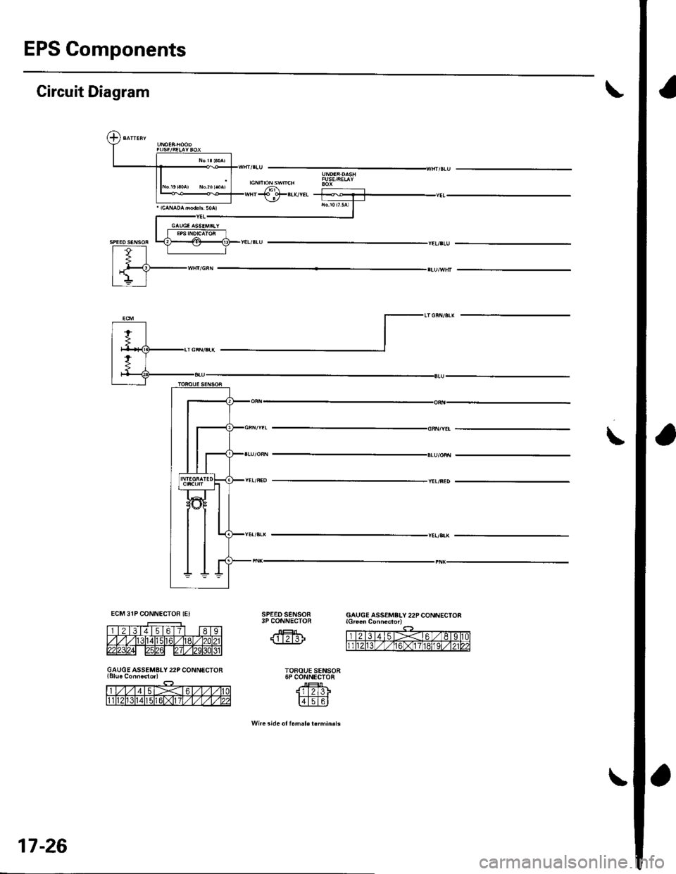
EPS Components
\Circuit Diagram
\
SPE€DSENSOR3P CONNECTOR
@
TOFOUE SENSOR6P CONNECTOR
lli2l3Fr;T;T-I(=J_:_LvJ
Wn. !ide ot f.m.l€ r.fmin.ls
GAUGE ASSEMBLY 22P CONNECTON
GAUGE ASSEMATY 22P CONNECTOR
17-26
Page 596 of 1139
Brakes
Conventional Brake Components
Special Tools ... ..... ... l9-2
Component Location Index ......................................... 19-3
Brake System Inspection and
Tests ............... .......... 19-4
Brake Pedal and Brake Pedal Position Switch
Adjustment .............. 19-6
Parking Brake Check and
Adjustment .............. 19-7
Brake System Bleeding ...................... 19-8
Brake System Indicator Circuit
Diagram ................... 19-9
Parking Brake Switch Test ................. 19-10
Brake Fluid Level Switch Test ...................................... 19-10
Front Brake Pads lnsoection and
Replacement ........... 19-11
Front Brake Disc Inspection ............... 19-13
Front Brake Calioer Overhaul ...................................... 19-14
Master Cylinder Replacement ........... 19-15
Master Cylinder Inspection ................ 19-16
Brake Booster
Pushrod Clearance Adjustment ................................ 19-16
Brake BoosterTest ................... .......... 19-18
Brake Booster Reolacement .............. 19-19
Rear Brake Pads Inspection and
Reolacement ........... 19-20
Rear Brake Disc Inspection ................ 19-22
Rear Brake Caliper Overhaul ....................................... 19-23
Brake Hoses and Lines Insoection .... 19-24
Brake Hose Reolacement ................... 19-25
Parking Brake Cable Replacement .............................. 19-26
ABS (Anti-lock Brake System)
Gomponents ... 19-29
Page 598 of 1139
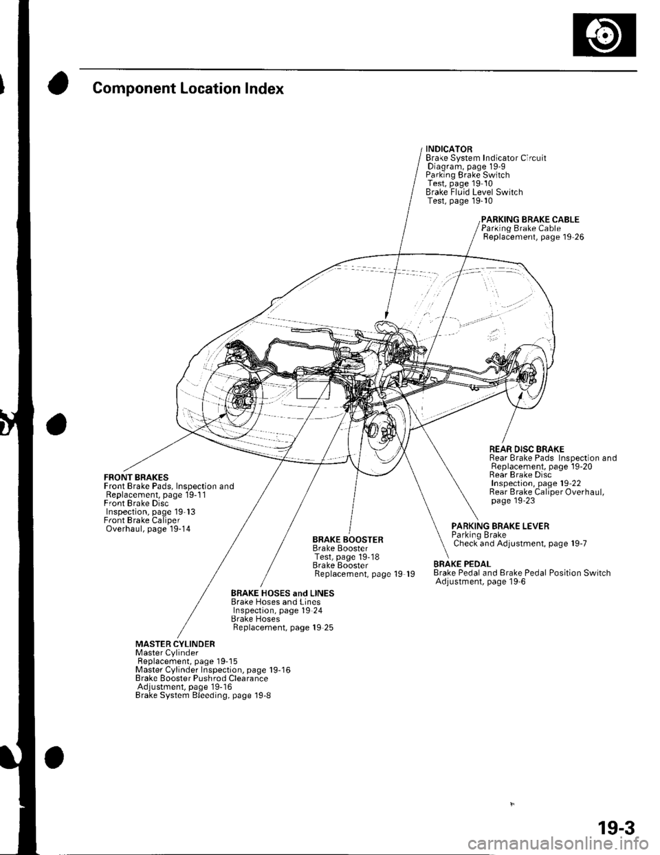
Component Location Index
FRONT BRAKESFront Brake Pads, Inspection andReplacement, page 19-1 1Front Brake DiscInspection, page 19'13Front Brake CaliperOverhaul, page 19-14
INDICATORBrake System Indicator CircuitDiagram, page 19-9Parking Brake SwitchTest, page 19 10Brake Fluid Level SwitchTest, page 19-10
BRAKE CABLE
BRAKE BOOSTERBrake BoosterTest, page 19-18Brake EoosterReplacement, page 19 19
Parking Brake CableReplacement, page 19 26
REAR DISC BRAKERear Brake Pads Inspection andReplacement, page l9-20Rear Brake DiscInspection, page 19'22Rear Brake Caliper Overhaul,page 19'23
PARKING BRAKE LEVERParkino BrakeCheck and Adjustment, page 19-7
BRAKE PEDALBrake Pedal and Erake Pedal Position SwitchAdjustment, page l9-6
BRAKE HOSES and LINESBrake Hoses and LinesInspection, page 19 24Brake HosesReplacement, page 19 25
MASTER CYLINDERMaster CylinderFl6^1.^6m6nr ^2^o 1O-18Master Cylinder Inspection, page 19-16Brake Booster Pushrod ClearanceAdjustment, page'19-16Brake System Bleeding, page 19-8
19-3
Page 604 of 1139
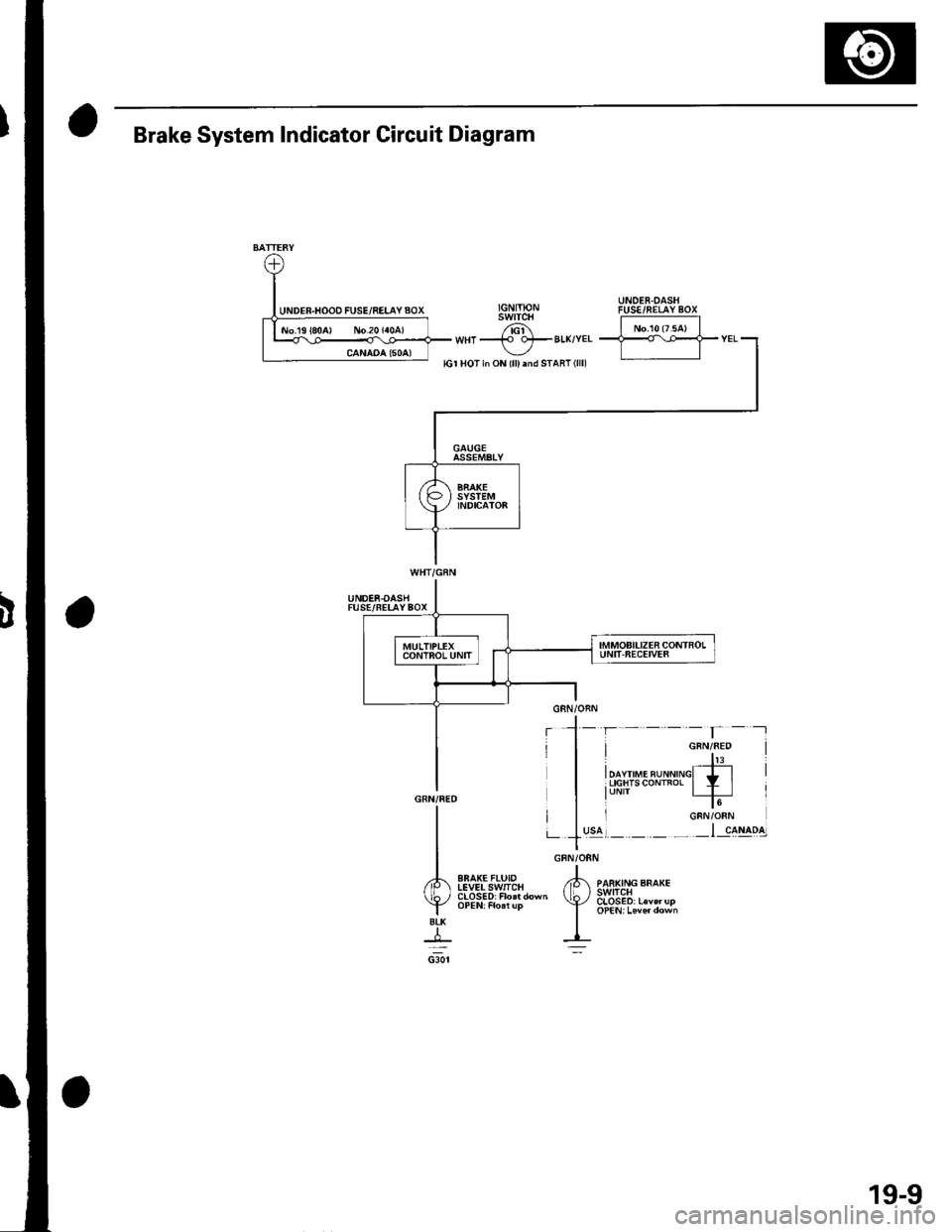
GRN/ORN
,tk ,o"","o ""o*.(b, 3s1E8,.""",,"
I oPEN,Leve,down
I-=:
I
A
YBtK
+csor
Brake System Indicator Circuit Diagram
UNDER.OASHFUSE/FELAYBOX
EBAK€FLUIDIEVELSwlICH
19-9
Page 623 of 1139
Brakes
Conventional Brake Components ................ 1 9-1
ABS (Anti-lock Brake System) Components
Comoonent Location lndex .............,........................... 19-30
General Troubleshooting Information ....................... 19-31
DTC Troubleshooting Index .............. 19-34
Symptom Troubleshooting Index ...,........................... 19-35
System Description ................. ........... 19-36
Circuit Diagram ......... 19-42
DTC Troubleshooting ............... .......... 19-45
ABS Indicator CircuitTroubleshooting ...................... 19-52
Brake System Indicator Circuit
Troubleshooting ...................... ....... 19-55
ABS Modulator-Control Unit Removal and
lnstallation ............. 19-57
Wheel Sensor Insoection ................... 19-59
Wheel Sensor Reolacement .............. 19-59
Page 636 of 1139
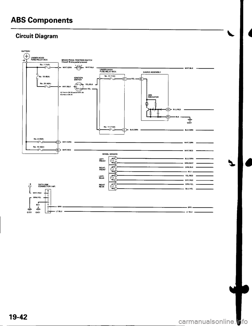
ABS Gomponents
Circuit Diagram
L "*'*" lJ I5l
r**'t?lI r+l
I ^ lo+-sN
Gu csl LqF**,
"'-----
G50l
19-42
Page 638 of 1139
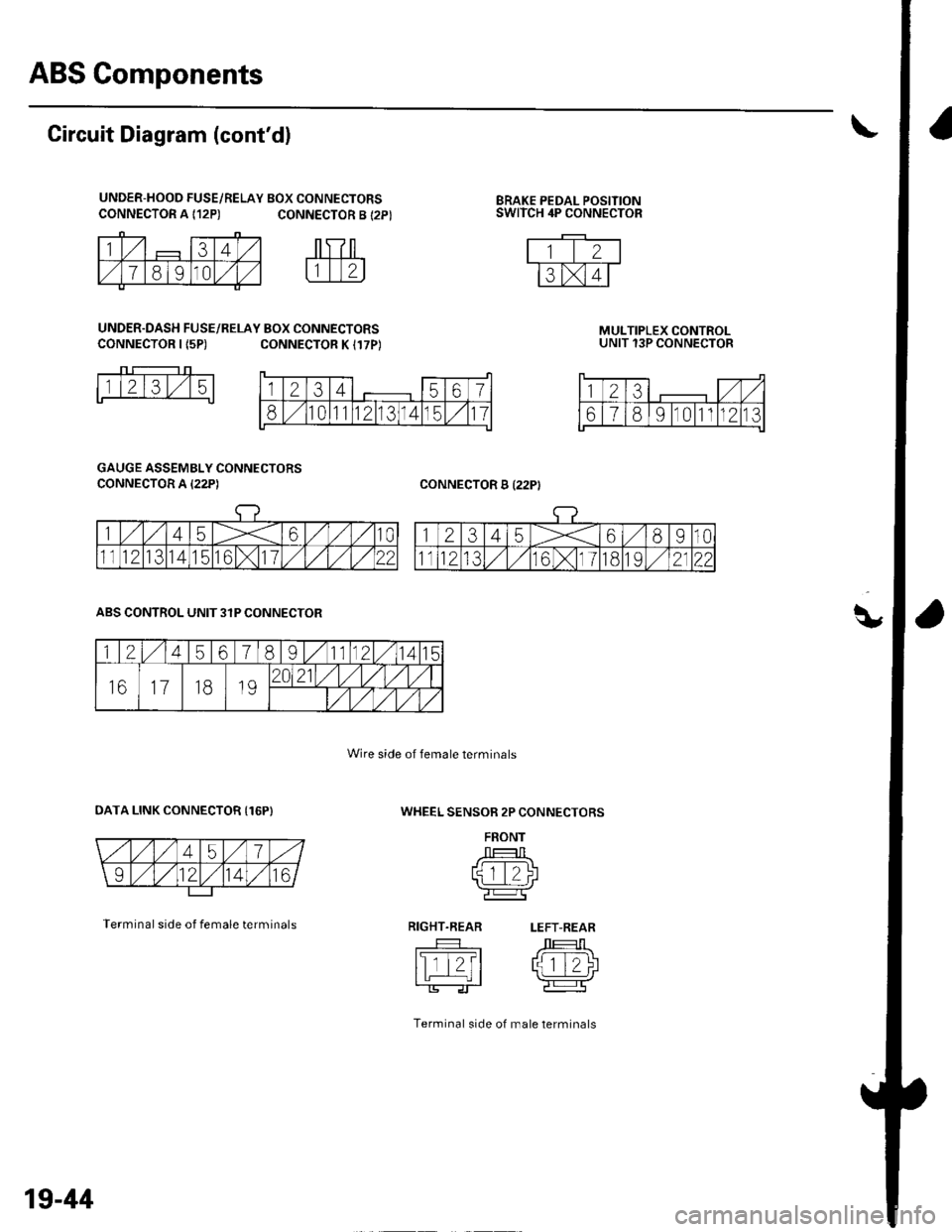
ABS Components
q,
CONNECTOR A {12P)BRAKE PEDAL POSITIONSWITCH 4P CONNECTOR
Circuit Diagram (cont'd)
UNDER-HOOD FUSE/RELAY BOX CONNECTORSCONNECTOR A {12P) CONNECTOR B {2P}
UNDER.DASH FUSE/RELAY BOX CONNECTORSCONNECTOR I {5P)CONNECTOR K I17P)MULTIPLEX CONTROLUNIT 13P CONNECTOR
CONNECTOR B I22PI
1l2l3l,/15
GAUGE ASSEMBLY CONNECTORS
CONNECTOR A I22P)
WHEEL SENSOR 2P CONNECTORS
FRONT
J --T:-l Ltqtt/)l'l L_.:-:J r\-r-----Tr'e:l
RIGHT.REAR LEFT-REAR
tslTt?t /J 1T-1\I tL | rlziJ
Terminal side of male lerminals
ABS CONTROL UNIT 3IP CONNECTOR
OATA LINK CONNECTOR {16P)
Terminal side of female terminals
Wire side of female terminals
1234567
810111213141511
123,/ ,/
67891011n213
1245678I11121415
161118192021/1,/1,/vl,/l
/t,/t/t,/t/
19-44
Page 773 of 1139
21-2
z t-'5
z t-o
z t-o
21-8
21-9
21-10
21-11
21-14
z t- to
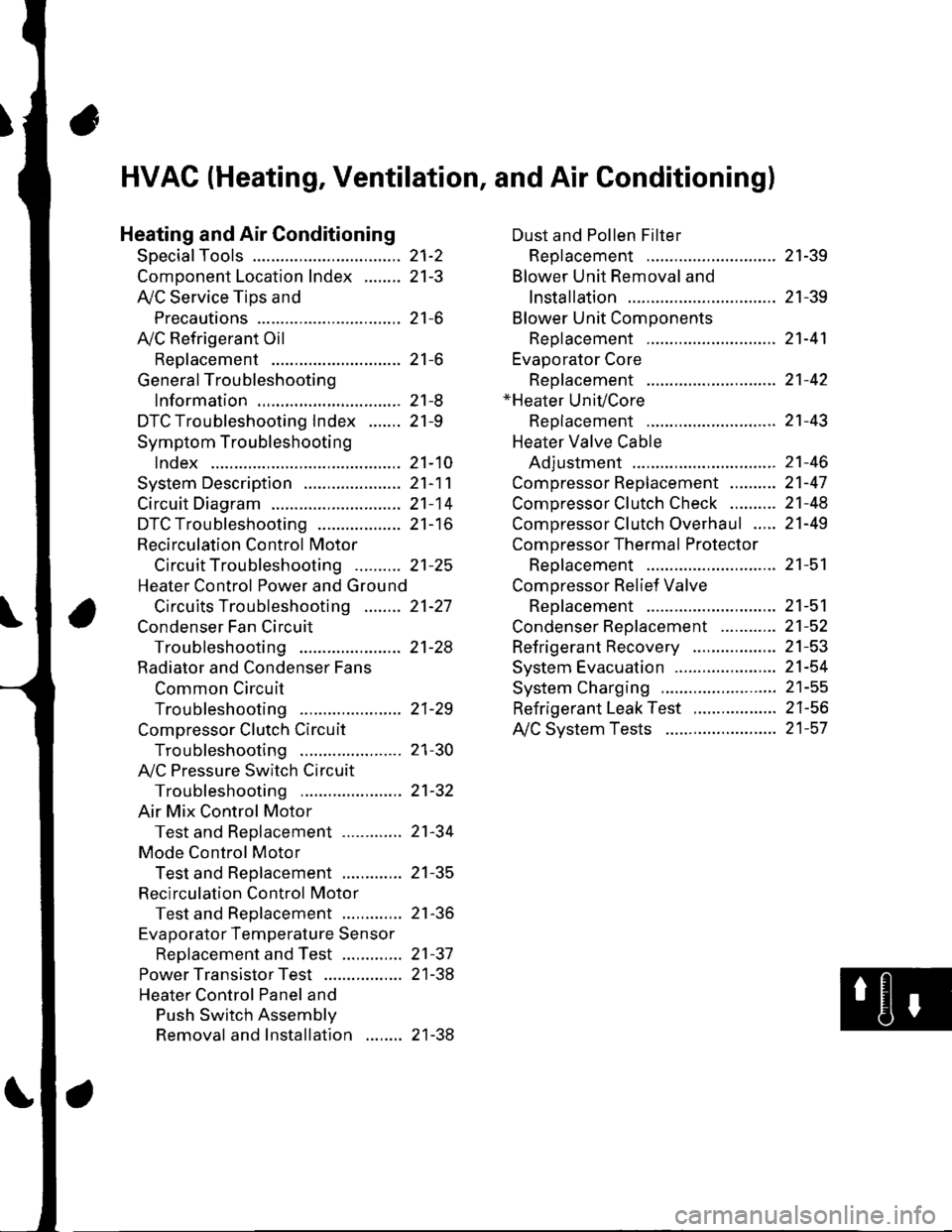
HVAC (Heating, Ventilation, and Air Gonditioningl
Heating and Air Conditioning
SpecialTools
Comoonent Location lndex ........
A/C Service Tios and
Precautions
A,/C Refrigerant Oil
ReDlacement
General Troubleshooting
lnformation
DTC Troubleshooting Index .......
Symptom Troubleshooting
1ndex..............
System Description .....................
Circuit Diagram
DTC Troubleshooting ..................
Recirculation Control Motor
CircuitTroubleshooting .......... 21-25
Heater Control Power and Ground
Circuits Troubleshooting ........ 21-27
Condenser Fan Circuit
Troubleshooting ...................... 21-28
Radiator and Condenser Fans
Common Circuit
Troubfeshooting ...................... 21-29
Compressor Clutch Circuit
Troubleshooting ...................... 21-30
A,/C Pressure Switch Circuit
Troubleshooting ...................... 21-32
Air Mix Control Motor
Test and Reolacement ............. 21-34
Mode Control Motor
Test and Replacement ............. 21-35
Recirculation Control Motor
Test and Reolacement ............. 21-36
Evaporator Temperature Sensor
Reolacement and Test ............. 21-31
Power Transistor Test ................. 21 -38
Heater Control Panel and
Push Switch Assemblv
Removal and Installation ........ 21-38
Dust and Pollen Filter
Reolacement ..21-39
Blower Unit Removal and
lnstallation ...... 21-39
Blower Unit Comoonents
ReDlacement ............................ 21-41
Evaporator Core
Reolacement ..21-42*Heater Unit/Core
ReDlacement ..21-43
Heater Valve Cable
Adjustment .....21-46
CompressorReplacement .......... 21-47
Comoressor Clutch Check .......... 21-48
Comoressor Clutch Overhaul ..... 21-49
Compressor Thermal Protector
Reo1acement ............................ 21-51
Comoressor Relief Valve
Reolacement ............................ 21-51
Condenser Reolacement ............ 21-52
Refrigerant Recovery .................. 21-53
System Evacuation ...................... 21-54
System CharginS ......................... 21-55
Refrigerant LeakTest .................. 21-56
A,/C Svstem Tests ........................ 21-57
Page 785 of 1139
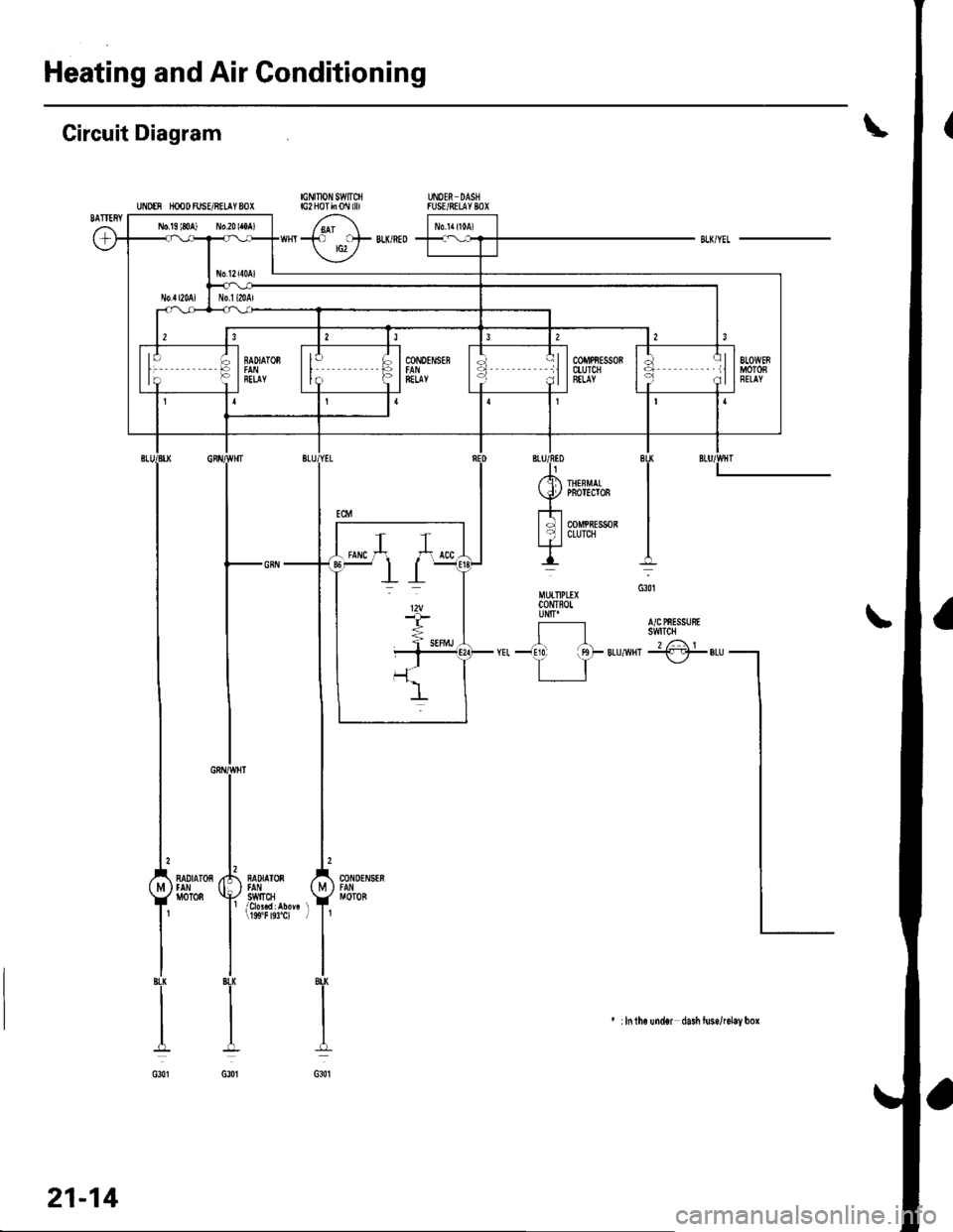
Heating and Air Conditioning
Gircuit Diagram
UNDEN rcODFUSVRELIYSOXUNOER DASNfUSE/8EIlYBOX|GNUION SWTCfilG2 HoI ii 0l\l llll
+. C}F BLK/RED rG2 /
II
I
I
In.G301
A/C PnESSUEtswTOt
t...iCF
RADIATOS
oT0n
NADIATOS) tAl'// swtlcllj 19S"F 193"C) l
CONDEN$N
MOTOB
I8u(
I
IBLX
I
G301
l
;
/ .I IHEFMAI
Y PBorEcro8
lTl *n*,*,|
MUITIPLD(CONTFOIUNITI
-!10. irgF 8Ll
TT
BLU
I ilntho undor dasi luse/lelay box
21-14