fuse HONDA CIVIC 2002 7.G Service Manual
[x] Cancel search | Manufacturer: HONDA, Model Year: 2002, Model line: CIVIC, Model: HONDA CIVIC 2002 7.GPages: 1139, PDF Size: 28.19 MB
Page 340 of 1139
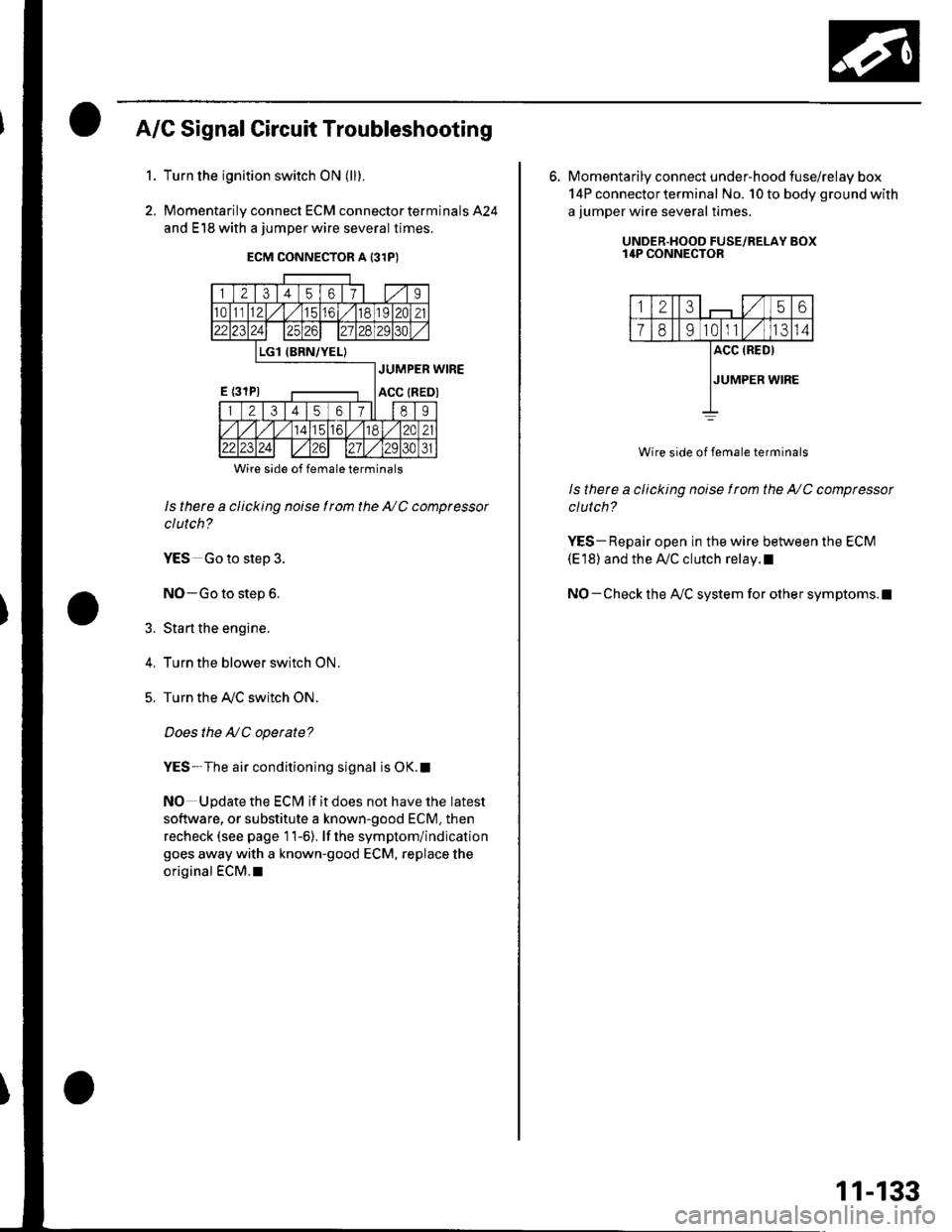
A/G Signal Circuit Troubleshooting
Turn the ignition switch ON (ll).
Momentarily connect ECM connector terminals 424
and E18 with a jumper wire several times.
1.
2.
5.
Wire side of female terminals
ls there a clicking noise I rom the NC compressor
clutch?
YES Go to step 3.
NO-Go to step 6.
Sta rt the engine.
Turn the blower switch ON.
Turn the Ay'C switch ON.
Does the NC operate?
YES-The air conditioning signal is OK.I
NO Update the ECM if it does not have the latest
software, or substitute a known-good ECM. then
recheck (see page 11-6). lf the symptom/indication
goes away with a known-good ECM, replace the
original €CM.l
6. Momentarily connect under-hood tuse/relay box
14P connector terminal No. 10 to body ground with
a jumper wire several times.
UNDER.HOOD FUSE/RELAY BOXI4P CONNECTOR
12356
1891011IJ14
ACC (RED)
JUMPER WIRE
Wire side of female terminals
ls there a clicking noise f rom the NC compressor
clutch?
YES- Repair open in the wire between the ECM(E'18) and the Ay'C clutch relay.l
NO- Check the A/C system for other symptoms.l
11-133
Page 344 of 1139
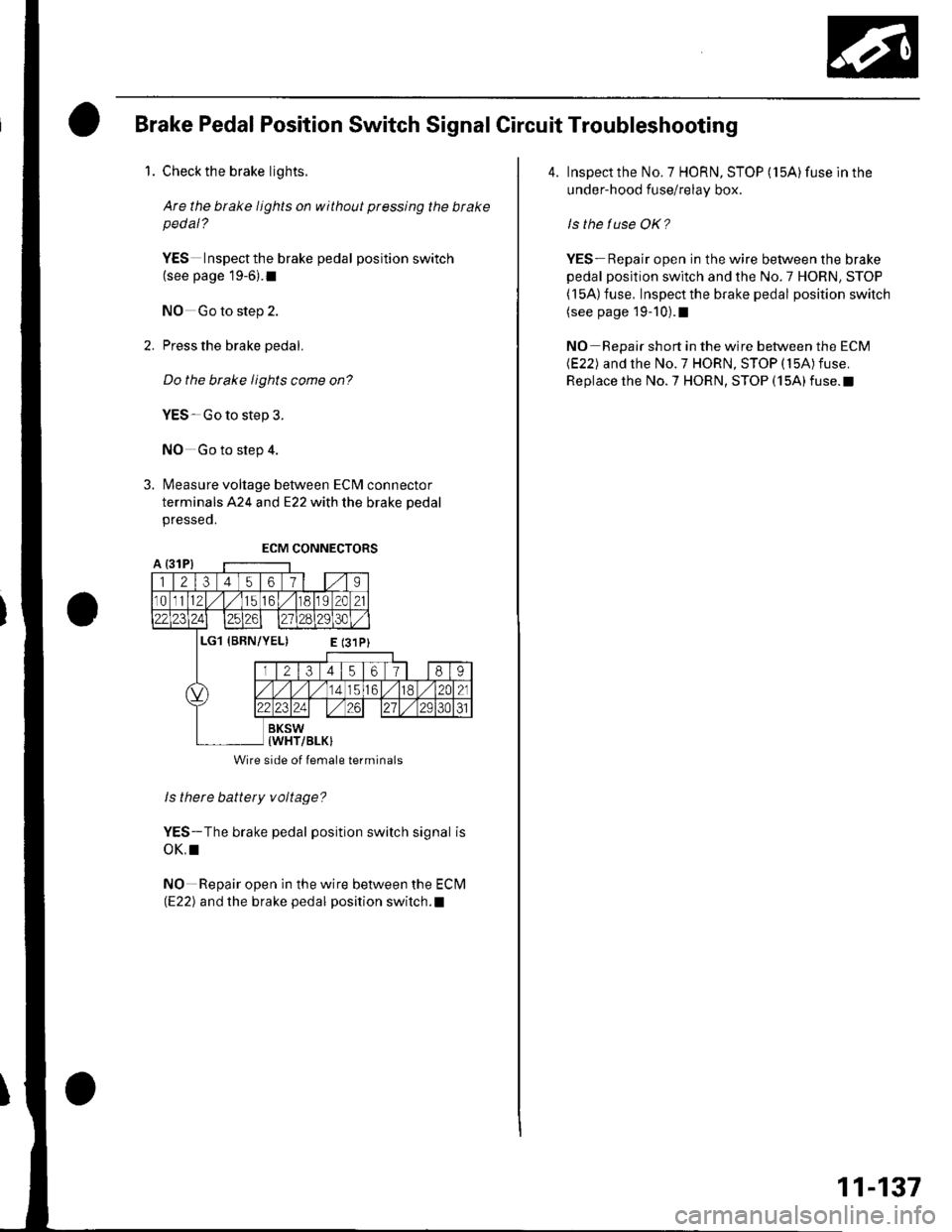
Brake Pedal Position Switch Signal Circuit Troubleshooting
1. Check the brake lights.
Are the brake lights on without pressing the brakepedal?
YES Inspectthe brake pedal position switch(see page 19-6).I
NO Go to step 2.
2. Press the brake pedal.
Do the brake lights come on?
YES-Go to step 3.
NO Go to step 4.
3. Measure voltage between ECM connector
terminals A24 and E22 with the brake pedal
presseo.
ls there battery voltage?
YES-The brake pedal position switch signal is
oK,I
NO Repair open in the wire between the Eclvl(E22) and the brake pedal position switch.l
Wire side of lemale terminals
4. Inspect the No. 7 HORN, STOP (15A) fuse ln the
under-hood fuse/relay box.
ls the tuse OK?
YES- Repair open in the wire between the brake
pedal position switch and the No.7 HORN, STOP( l5A) fuse, Inspect the brake pedal position switch(see page 19-10).1
NO Repair short in the wire between the ECM(E22) and the No.7 HORN, STOP (15A)fuse.
Replace the No.7 HORN, STOP (15A)fuse.t
11-137
Page 346 of 1139
ECM ldle Learn Procedure
The idle learn procedure must be done so the ECM can
learn the engine idle characteristics.
Do the idle learn procedure whenever you do any of
these actions:. Disconnect the battery.
Replace the ECM or disconnect its connector.
Reset the ECM.
NOTE: Erasing DTCS with the Honda PGM Tester
does not require you to do the idle learn procedure.
Remove the No.6 ECU {ECM) ( 15A) fuse from the
under-hood fuse/relay box.
Remove the No.19 baftery (80A) fuse from the under-
hood fuse/relay box.
Remove PGM-FI main relay 1.
Remove any of the wires from the under-hood fuse/
retay Dox.
Disconnect any of the connectors from the under
hood fuse/relay box.
Disconnect the connector between the engine
compartment wire harness and ECM wire harness.
Disconnect the G2 terminal from the transmission
ho u srng.
Disconnectthe G'l terminal from the body.
Disconnectthe G101 terminal from the cylinder head
cover.
Procedure:
To complete the idle learn procedure, do this:
1. Make sure all electrical items (Ay'C, audio, rear
defogger, l:ghts, etc.,) are off.
2. Start the engine, and hold it at 3,000 rpm with no
load {in neutral) until the radiator fan comes on, or
until the engine coolanttemperature reaches 194"F(90'c).
3. Let the engine idle for about 5 minutes with the
throttle fully closed.
NOTE: lf the radiator fan comes on, do not include its
running time in the 5 minutes.
11-139
Page 348 of 1139
Fuel Pump Circuit Troubleshooting
lf you suspect a problem with the fuel pump, check that
the fuel pump actually runs; when it is on, you will hear
some noise if you listen to the fuel fill port with the fuel
fill cap removed. The fuel pump should run for 2
seconds when the ignition switch is first turned on. lf
the fuel pump does not make noise, check as follows:
1. Turn the ignition switch OFF.
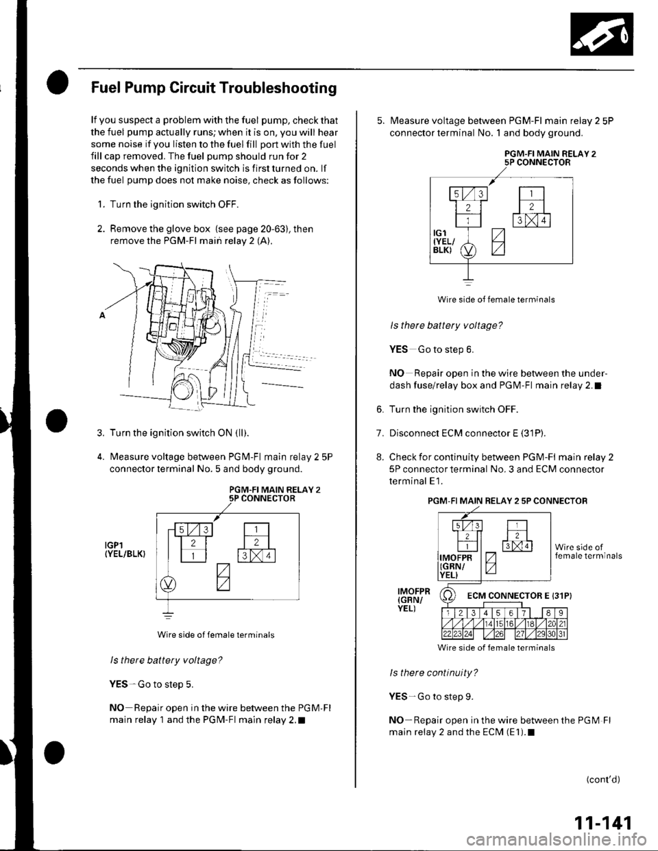
2. Remove the glove box {see page 20-63), then
remove the PGM-FI main relay 2 (A).
Turn the ignition switch ON {ll).
Measure voltage between PGM-Fl main relay 2 5P
connector lerminal No. 5 and body ground.
PGM.FI MAIN RELAY 25P CONNECTOR
IGPl(YEL/BLK}
Wire side of female terminals
ls there battery voltage?
YES-Go to step 5.
NO Repair open in the wire between the PGM'Fl
main relay 1 and the PGM-Fl main relay 2.t
3.
5. N4easure voltage between PGM-Fl main relay 2 5P
connector terminal No. 1 and body ground.
PGM.FI MAIN RELAY 25P CONNECTOR
Wire side oJ female terminals
ls there battery voltage?
YES Go to step 6.
NO Repair open in the wire between the under-
dash fuse/relay box and PGM-Fl main relay 2.1
6. Turn the ignition switch OFF.
7. Disconnect ECM connector E (31P).
8. Check for continuity between PGM-FI mainrelay2
5P connector terminal No. 3 and ECM connector
terminal E1.
PGM-FI MAIN RELAY 2 5P CONNECTOB
Wire side of female terminals
ls there continuity?
YES-Go to step 9.
NO-Repair open in the wire between the PGM Fl
main relay 2 and the ECM (E1).1
IMOFPR(GBN/YEL)
(cont'd)
11-141
Et2lFtxm
7-
z
ECM CONNECTOR E 131P}
Page 363 of 1139
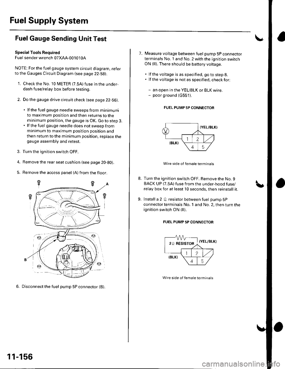
Fuel Supply System
Fuel Gauge Sending Unit Test
Special Tools Required
Fuel sender wrench 07XAA-001010A
NOTE; For the fuel gauge system circuit diagram, referto the Gauges Circuit Diagram (see page 22-58||.
1. Checkthe No. 10 fUETER {7.5A)fuse in the under-
dash fuse/relay box before testing.
2. Do the gauge drive circuit check (see page 22-56|l.
' lf the fuel gauge needle sweeps from minimuni
to maximum position and then returns to the
minimum position. the gauge is OK. Go to step 3.. lf the fuel gau ge need le does not sweep from
minimum to maximum position position and
then return to the minimum position, replace thegauge assembly and retest.
3. Turn the ignition switch OFF.
4. Remove the rear seat cushion {see page 20-80).
5. Remove the access panel (A)from the floor.
6. Disconnect the fuel pump 5P connector {B).
-ztr
11-156
7. Measure voltage between fuel pump 5P connectorterminals No. 1 and No. 2 with the ignition switchON (ll). There should be battery voltage.
. lf the voltage is as specified, go to step 8.. lf the voltage is notasspecified,checkfor:
- an open in the YEUBLK or BLK wire.- poor ground (G551).
FUEL PUMP 5P CONNECTOR
Wire side of female terminals
Turn the ignition switch OFF. Remove the No. 9BACK UP (7.5A)fuse from the under-hood fuse/
relay box for at least 10 seconds, lhen reinstall it.
Install a 2 Q resistor between fuel pump 5P
connector lerminals No. 1 and No. 2, then turn the
ignition switch ON (ll).
FUEL PUMP 5P CONNECTOR
-VVV-
29RESISTOR,
=-a
{Y
\
//,(elrt \
\45/
{YEL/BLK)
Wire side of female terminals
Page 364 of 1139
10. Checkthatthe pointerof thefuel gauge indicates"F".
. lf the pointer does not indicate "F", replace the
ga uge.. lf the pointer indicates "F", inspect the fuel
gauge sending unit.
NOTE: The pointer of the fuel gauge retu rns to the
bottom of the gauge dial when the ignition switch
is OFF, regardless of the fuel level. -
11. Relieve the fuel pressure (see page 11-144\.
12. Remove the fuelfill cap.
13. Disconnect the quick-connect fittings from the fuel
pump.
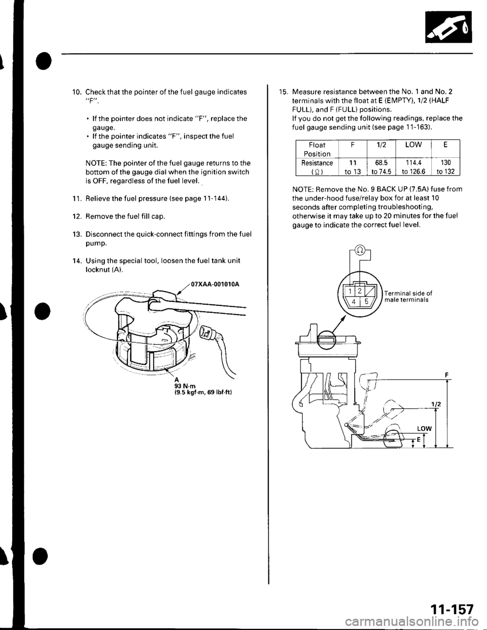
14. Using the special tool, loosen the fuel tank unit
locknut (A).
A93Nm{9.5 ksf.m,69 lbf.ft}
15. Measure resistance between the No. 1 and No.2
terminals with the float at E (EN4PTY), 'l12 \HALF
FULL), and F {FULL) positions.
lf you do not get the following readings, replace the
fuel gauge sending unit {see page 1'1-163).
Float
Position
F'U2LOWE
Resistance
{0)
11
to 13
68,5
to 74.5
114.4
to 126.6
130
to 132
NOTE: Remove the No. 9 BACK UP (7.5A) fuse from
the under-hood fuse/relay box for at least 10
seconds after completing troubleshooting,
otherwise it may take up to 20 minutes for the fuel
gauge to indicate the correct fuel level.
11-157
Page 365 of 1139
Fuel Supply System
1.
4,
Low Fuel Indicator Test
Do the fuel gauge sending unit test (see page 11,
rcol.
. lf the system is OK, go to step 2.. lf the system has any malfunction, repair it.
Turn the ignition switch OFF. Remove the No. 9
BACK UP (10A) fuse from the under-hood fuse/
relay box for at least 30 seconds, then reinstall it.
Turn the ignition switch ON (ll) with the float at the
E (EMPry) position.
. lf the low fuel indicator is on, go to step 4.. lf the low fuel indicator is not on, refer to the low
fuel indicator Circuit Diagram (see page 22-58)
and check the circuit.
Turn the ignition switch OFF. Remove the No. 9
BACK UP (10A) fuse from the under-hood fuse/
relay box for at least 30 seconds, then reinstall it.
Lift the float above the LOW position.
. lf the lowfuel indicatorgoes off,the system is OK.. lf the low fuel indicator is still on, refer to the low
fuel indicator Circuit Diagram {see page 22-58),
and check the circuit.
11-158
\,
Page 384 of 1139
15.
to.
Turn the ignition switch OFF.
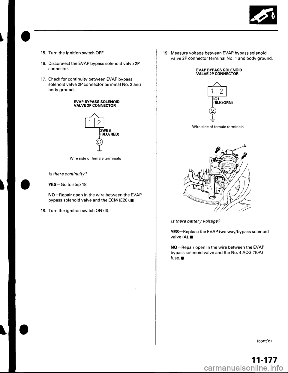
Disconnect the EVAP bypass solenoid valve 2P
connecror.
Check for continuity between EVAP bypass
solenoid valve 2P connector terminal No. 2 and
body ground.
17.
EVAP BYPASS SOLENOIDVALVE 2P CONNECTOR
'18.
Wire side oI Iemale terminals
ls there continuity?
YES Go to step 18.
NO-Repair open in the wire bet\iveen the EVAP
bypass solenoid valve and the ECM (E20).1
Turn the ignition switch ON (ll).
2
tG'l
'19. Measure voltage between EVAP bypass solenoid
valve 2P connector terminal No. 1 and body ground.
EVAP BYPASS SOLENOIDVALVE 2P CONNECTOR
{BLK/ORN)
Wire side ol lemale terminals
ls there battery voltage?
YES Replace the EVAP two way/bypass solenoid
valve (A).1
NO-Repair open in the wire between the EVAP
bypass solenoid valve and the No. 4 ACG (10A)
fuse.l
{cont'd)
11-177
Page 388 of 1139
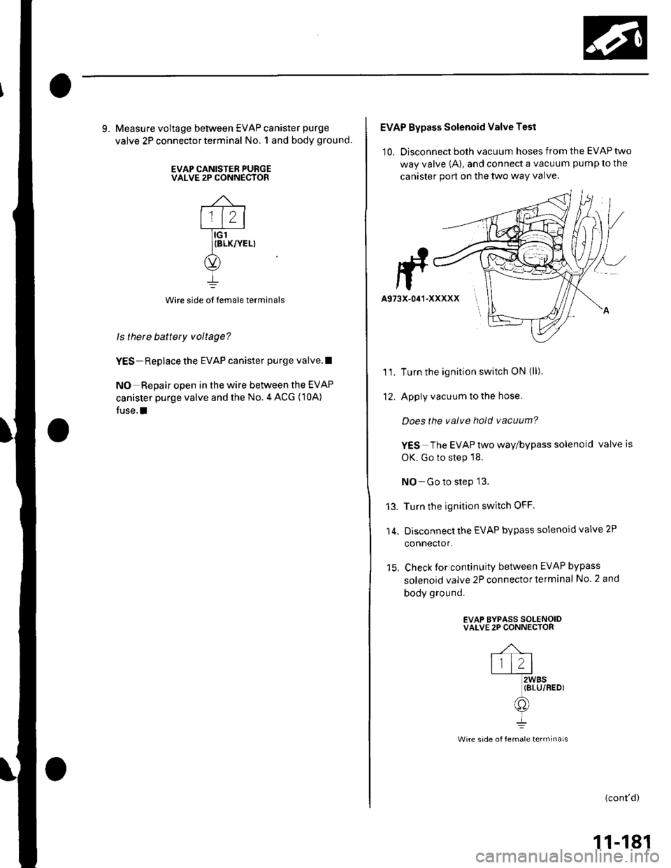
9. Measure voltage between EVAP canister purge
valve 2P connector terminal No. 1 and body ground.
EVAP CANISTER PURGEVALVE 2P CONNECTOR
Wire side oI lemale terminals
ls thete battery voltage?
YES- Replace the EVAP canister purge valve.l
NO Repair open in the wire between the EVAP
canister purge valve and the No.4 ACG (10A)
fuse.I
EVAP Bypass Solenoid Valve Test
10. Disconnect both vacuum hoses from the EVAP two
way valve {A), and connect a vacuum pump to the
canister port on the two way valve.
Turn the ignition switch ON (ll).
Apply vacuum to the hose.
Does the valve hold vacuum?
YES The EVAP two way/bypass solenoid valveis
OK. Go to step 18.
NO-Go to step 13.
Turn the ignition switch OFF.
Disconnect the EVAP bypass solenoid valve 2P
connector.
Check for continuity between EVAP bypass
solenoid valve 2P connector terminal No. 2 and
body ground.
EVAP BYPASS SOLENOIDVALVE 2P CONNECTOR
11.
'It
14.
(cont'd)
11-181
Wire side of female terminals
Page 390 of 1139
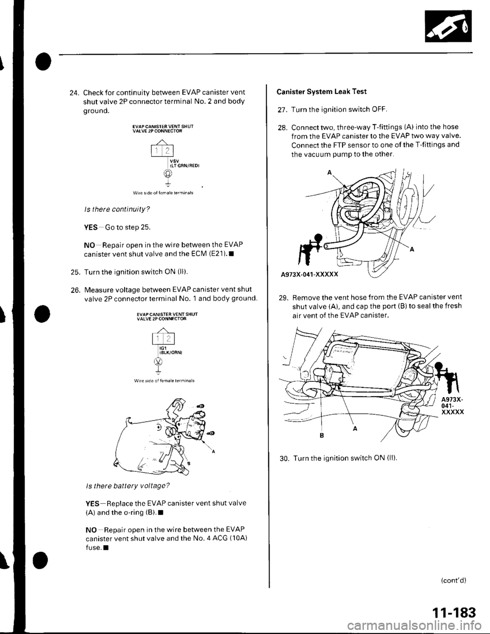
25.
26.
24. Check for continuity between EVAP canister vent
shutvalve 2Pconnectorterminal No.2 and body
ground.
VATVE 2P CONNECTOR
-4-
lr 2l-T_*u
ILTGFN/REDI
@
wn€ s de ol l€ma1e terminals
ls therc continuity?
YES Go to step 25.
NO Repair open in the wire between the EVAP
canister vent shut valve and the ECIVI (E21).1
Turn the ignition switch oN (ll).
Measure voltage between EVAP canister vent shut
valve 2P connector terminal No. 1 and body ground.
EVAPCANISTER VENT SHUTVALVE 2PCONNECTOR
Wlreside oflem. € rerm na s
ls there battery voltage?
YES Replace the EVAP canister vent shut valve
(A) and the o-ring (B).I
NO Repair open in the wire between the EVAP
canister vent shut valve and the No. 4 ACG (10A)
fuse.I
Canister System Leak Test
27. Turn the ignition switch oFF.
28, Connecttwo, three-way T-fittings (A) intothehose
from the EVAP canister to the EVAP two way valve.
Connect the FTP sensor to one of the T-fittings and
the vacuum pump to the othel
29. Remove the vent hose from the EVAP canister vent
shut valve (A), and cap the port (B) to seal the fresh
air vent of the EVAP canister.
30. Turn the ignition switch ON (ll).
(cont'd)
11-183