fuse HONDA CIVIC 2002 7.G Owner's Manual
[x] Cancel search | Manufacturer: HONDA, Model Year: 2002, Model line: CIVIC, Model: HONDA CIVIC 2002 7.GPages: 1139, PDF Size: 28.19 MB
Page 222 of 1139
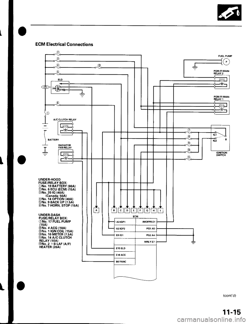
J/-\-1\_/
BEIAY2
A/C CLUTCH RELAY
RAOIATOR
I
)
T
UNDER.HOODFUSE/RELAY BOX:ONo. 19 BATTERY (8oA)ONo. 6 ECU (ECM) (15A1(3)No.20lG {40A1{Canada:50A}ONo. l4 OPTION {40A1€)No. 9 BACK uP (7.5A1lo)No. 7 HORN, STOP {15A}
UNDER.DASHFUSE/RELAY BOX:ONo. 17 FUEL PUMP{15A}@No. ,t ACG {10A)ONo. 1 IGN COIL (1sA)q)No. 10 METER (7.5A)0)No. 14 A/C CLUTCHRELAY IlOA)@No.2 +B LAF (A/F)HEATER (2OA)
(cont'd)
11-15
Page 238 of 1139
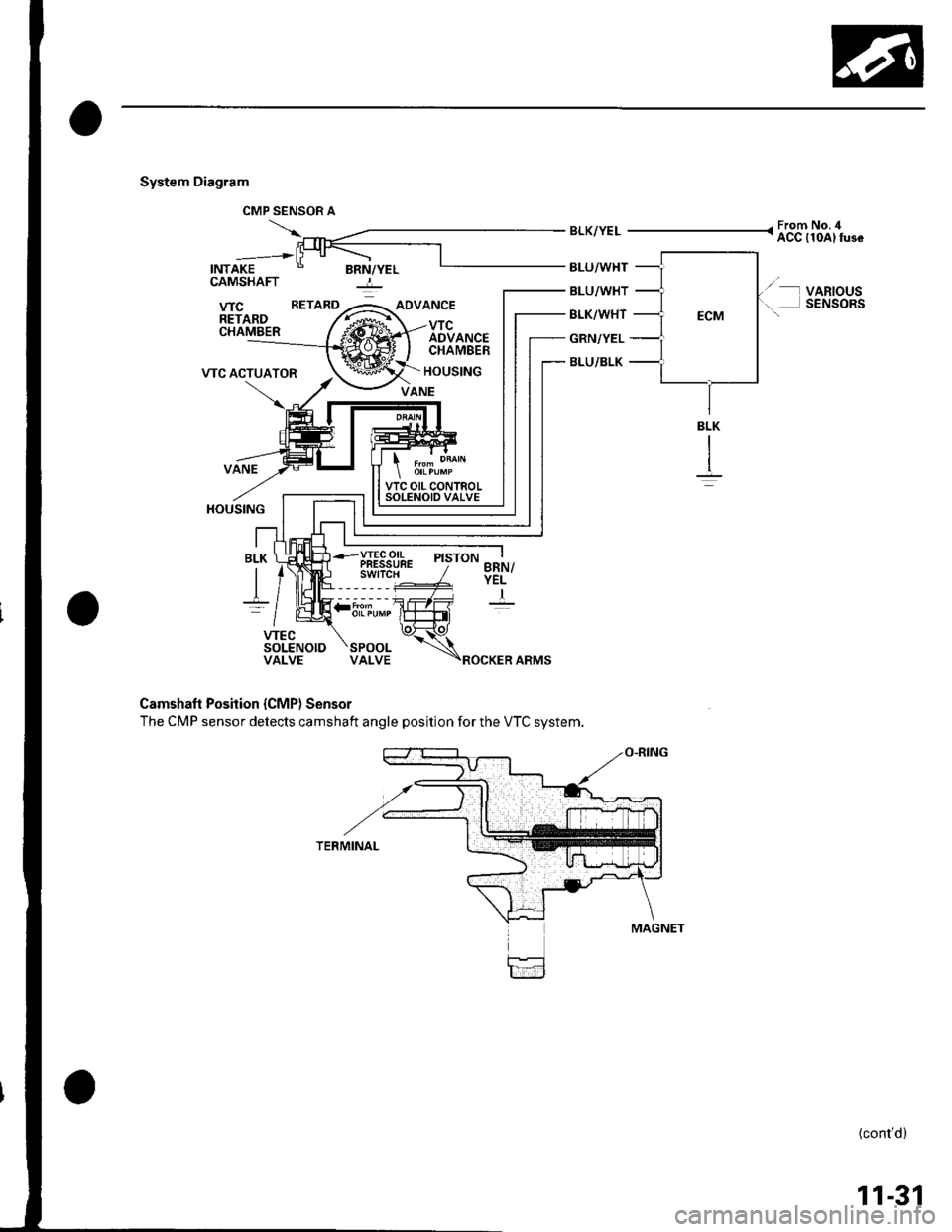
System Diagram
INTAKE
CMP SENSOR A
BRN/YELBLU/WHT
BLU/WHT
BLK/WHT
GRN/YEL
BLU/BLK
From No. ilACC {10A) fuse
VARIOUSSENSORS
CAMSHAFT -:-
BLK
It
Camshaft Position {CMP} Sensor
The CMP sensor detects camshaft angle position for the VTC system.
{cont'd}
11-31
:5i.T,""
Page 244 of 1139
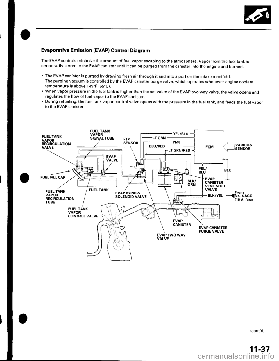
Evaporative Emission (EVAPI Control Diagram
The EVAP controls minimize the amount of fuel vapor escaping to the atmosphere. Vapor from the fuel tanK rstemporarily stored in the EVAP canister until it can be purged from the canister into the engine and burneo.
. The EVAP canister is purged by drawing fresh air through it and into a port on the intake manifold.The purging vacuum is controlled by the EVAP canister purge valve, which operates whenever engine cootanttemperature is above 149'F (65"C).
'WhenvaporpressureinthefueltankishigherthanthesetvalueoftheEVAPtwowayvalve,thevalveopensano
regulates the flow of fuel vapor to the EVAP canister.'Duringrefueling,thefueltankvaporcontrol valve opens with the pressure in the fuel tank, and feeds the fuel vaDorto the EVAP canister.
FUEL TANKVAPORRECIRCULATIONVALVE
FUEL TANKVAPORSIGNAL TUBE
BLU/RED
FUEL FILL CAP
BLK
+EVAPCANISTER
FUEL TANKVENT SHUTVALVE
BLK/YELFrom--
EVAPCANISTER
EVAP TWO WAYVALVE
(cont'd)
11-37
Page 251 of 1139
Fuel and Emissions Systems
a
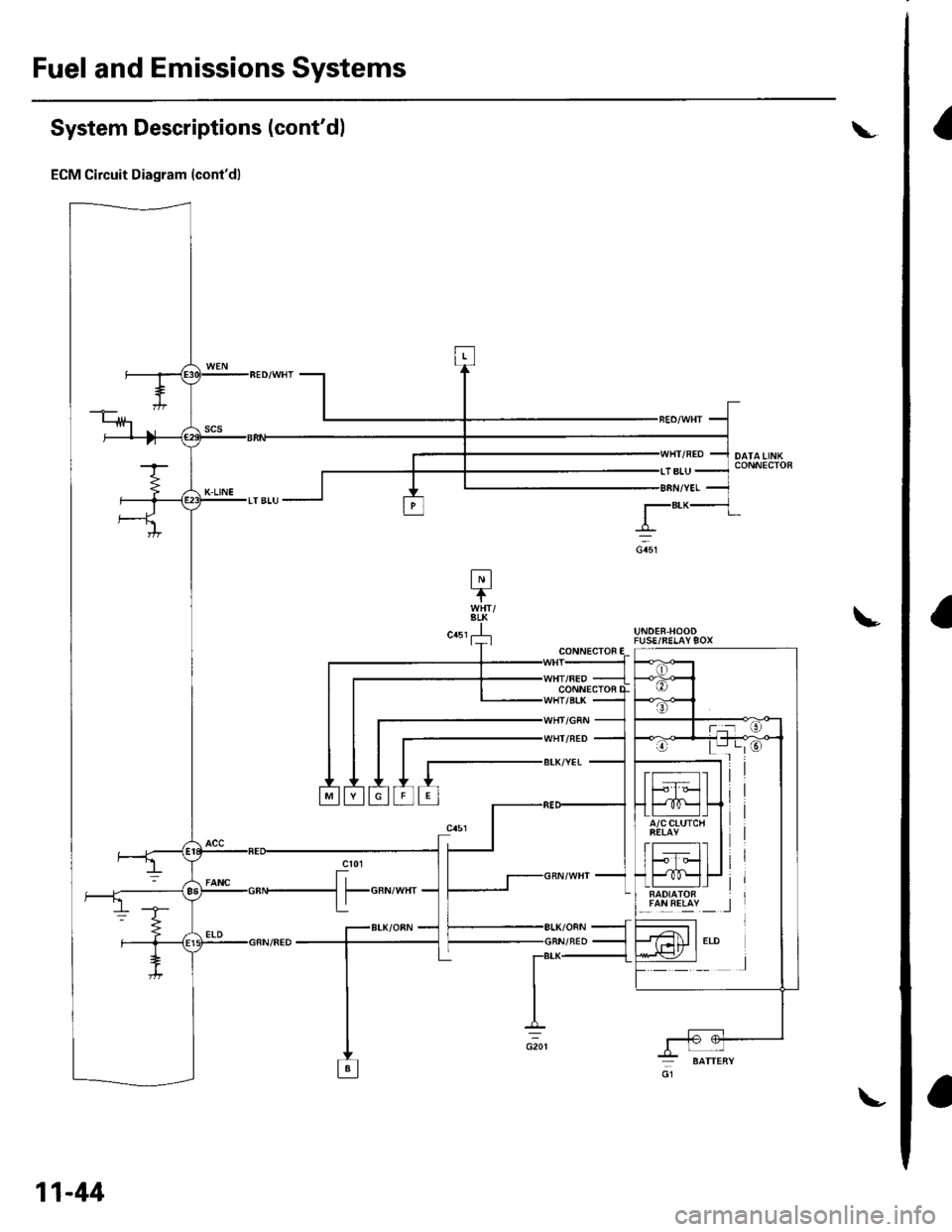
System Descriptions (cont'dl
ECM Circuit Diagram (cont'd)
L
!UNDER.HOODFUSE/RELAY9OX
lalLREllY _ _l
CONN€CTOF
CONNECTOi
WHI/NED
BLK/YET
11-44
Page 252 of 1139
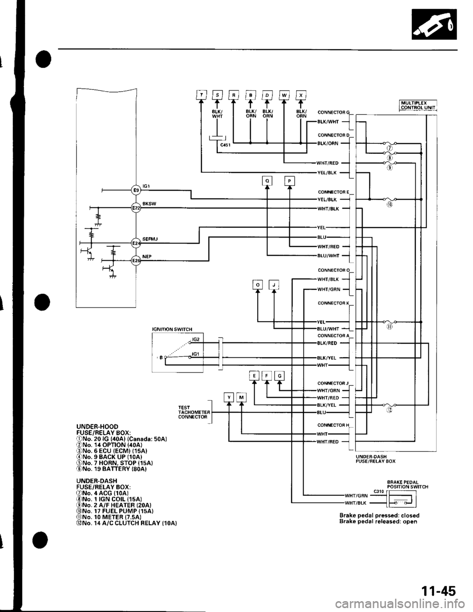
""rr"a* JIr''lHr/cnN 1
CONNECTOR E
CONNECTOi K
CONNECTOFJ/GRN
IGNITIONSWITCH
lG2
'I
TESTTACHOMETERCONNECTO8
UNDER.HOOD
UNDER.DASHFUSE/RELAY BOX:
UNDER.DASHFUSE/FELAY BOX
Brake pedal pressed: closedBrake pedal releasedr open
POStTtON SWTTCH
,or"-9J3{51re* _{F "_.rl
4 ACG (1oAt1 tGN CO|L t15A)2 A/F HEATER {2OA)17 FUEL PUMP I15A}1O METER {7.5AI14 A/C CLUTCH RELAY {1OA}
11-45
Page 276 of 1139
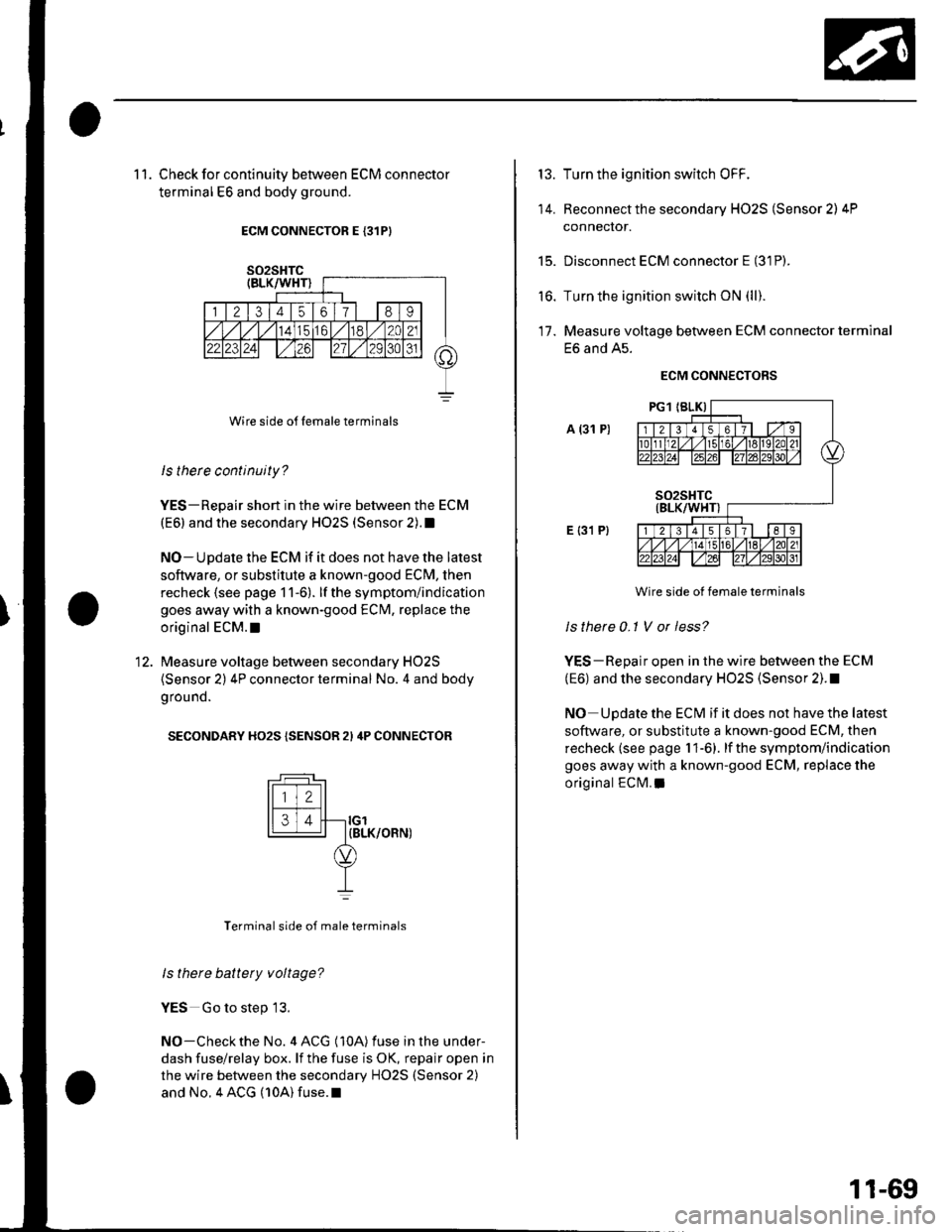
1 1. Check for continuity between ECM connector
terminal E6 and body ground.
ECM CONNECTOR E {31PI
Wire side o{f Iemale terminals
ls therc continuity?
YES-Repair short in the wire between the ECM
(E6) and the secondary HO2S (Sensor 2).1
NO-Update the ECM if it does not have the latest
soflware, or substitute a known-good ECM, then
recheck (see page 1 1-6). lf the symptom/indication
goes away with a known-good ECM, replace the
original ECM.I
Measure voltage between secondary HO2S
(Sensor 2) 4P connector terminal No. 4 and body
g rou nd.
SECONDARY HO2S {SENSOR 2I 4P CONNECTOR
tFff I
l[faJl--ro'14 | IBLK/OFN)
YI
Terminal side of male terminals
ls there battety voltage?
YES Go to step 13.
NO-Checkthe No. 4 ACG (10A) fuse in the under-
dash fuse/relay box. lf the fuse is OK, repair open in
the wire between the secondary HO2S (Sensor 2)
and No. 4 ACG (10A) fuse.l
13.
14.
t5.
to.
Turn the ignition switch OFF.
Reconnect the secondary HO2S (Sensor 2) 4P
connector.
Disconnect ECM connector E (31P).
Turn the ignition switch ON (ll).
Measure voltage between ECM connector terminal
E6 and A5.
ECM CONNECTORS
A (31 P)
E {31 P}
Wire side ot female terminals
Is there 0-1 V or less?
YES-Repair open in the wire between the ECM
(E6) and the secondary HO2S (Sensor 2). !
NO Update the ECM if it does not have the latest
software, or substitute a known-good ECM, then
recheck (see page 1 1-6). lf the symptom/indication
goes away with a known-good ECM, replace the
original ECM. a
17.
11-69
Page 280 of 1139
16.Test-drive the vehicle for several minutes in the
range of the freeze data or under various
conditions if there was no freeze data.
Check for a DTC or a Temporary DTC with the scan
Tool.
ls DTC or Temporary DTC P0301, P0302, P0303
or P0304 indicated?
YES Go to step 18.
NO lntermittent misfire due to bad contact at the
injector connector (no misfire at this time). Make
sure the injector connection is secure. Check for
poor connections or loose terminals at the
injector.l
Determine which cylinder(s) had the misfire.
Does the misf ire occur in the cylinder where the
i njector w as exchanged ?
YES- Replace the faulty injector.I
NO-Go to step 19.
Turn the ignition switch OFF.
Disconnect the ignition coil 3P connector from the
problem cylinder.
Turn the ignition switch ON (ll).
't7 .
18.
19.
20.
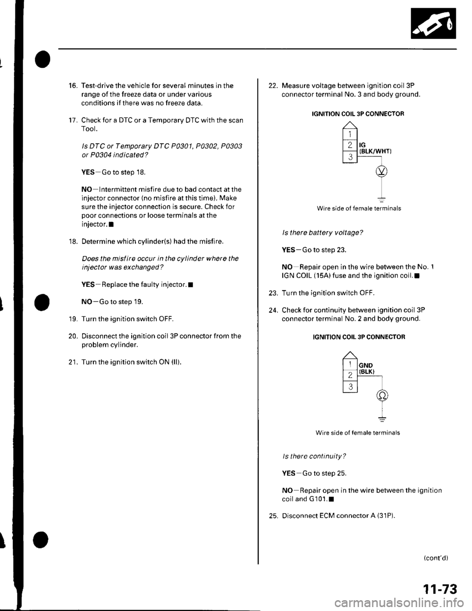
22. Measure voltage between ignition coil 3P
connector terminal No. 3 and body ground.
IGNITION COIL 3P CONNECTOR
Wire side ol female terminals
ls there battery voltage?
YES-Go to step 23.
NO Repair open in the wire between the No. 1
IGN COIL (15A)fuse and the ignition coil.I
Turn the ignition switch OFF.
Check for continuity between ignition coil 3P
connector terminal No. 2 and body ground.
IGNITION COIL 3P CONNECTOR
Wire side ot female terminals
ls there continuity?
YES Go to step 25.
NO Repair open in the wire between the ignition
coiland G101.1
Disconnect ECM connector A {31P)
23.
24.
(cont'd)
11-73
Page 288 of 1139
DTC P0563: ECM Power Source Circuit
U nexpected Voltage
1. Reset the ECI\4 {see page l1-4}.
2. Turn the ignition switch OFF.
3. Wait 5 seconds.
4. Turn the ignition switch ON {lll.
ls DTC P0563 indicated?
YES Go to step 5.
NO-lntermiltent failure, system is OK at this time.
Check for poor connections or loose terminals at
the No. 6 ECU (ECM) {15 A) fuse in the under-hood
fuse/relay box and at the ECM.I
Turn the ignition switch OFF.
Disconnect ECI\4 connector E {31P).
Turn the ignition switch ON (ll).
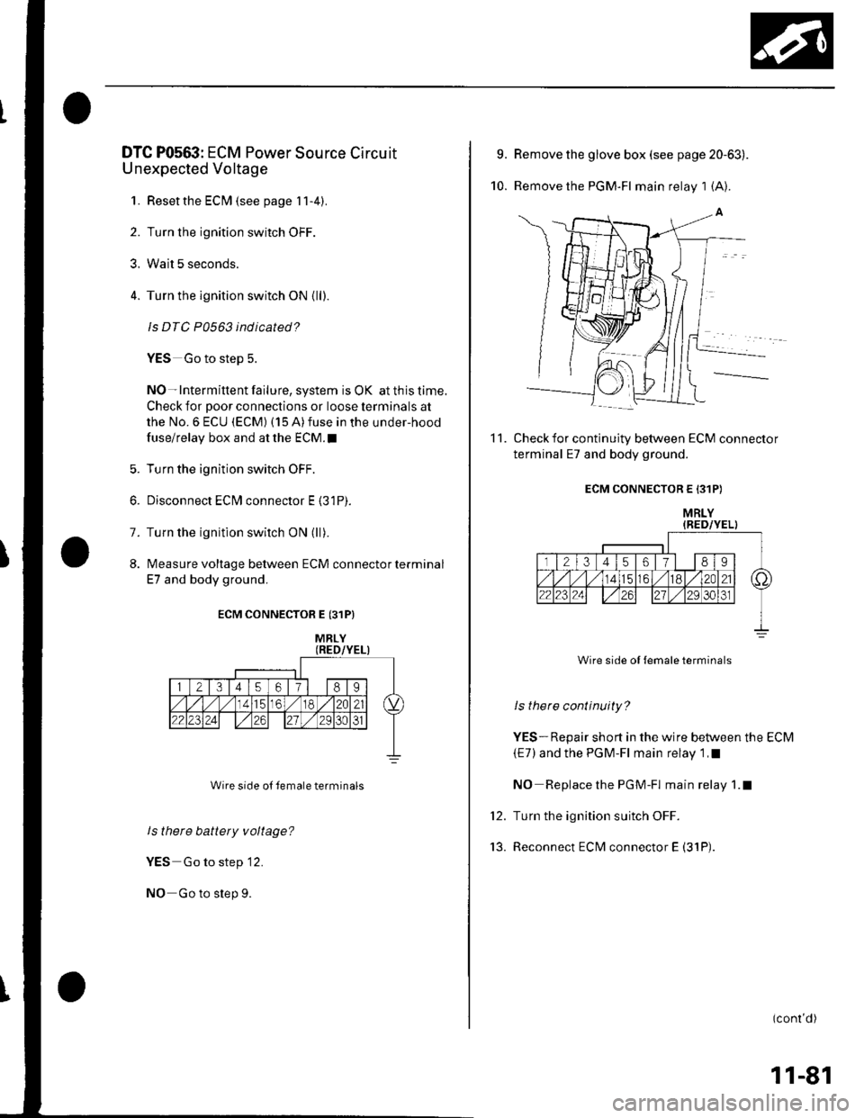
lvleasure voltage between ECM connector terminal
E7 and body ground.
6.
7.
8.
ECM CONNECTOR E {31P}
Wire side ol remale terminals
ls there battery voltage?
YES Go to step 12.
NO Go to step 9.
MRLY
9.
10.
Remove the glove box (see page 20-63).
Remove the PGM-FI main relay 1 (A7.
Check for continuity between ECM connector
terminal E7 and body ground.
ECM CONNECTOR E 131P)
MRLY{RED/YEL)
Wire side of {emale terminals
ls there continuity?
YES-Repair short in the wire between the ECM
{E7) and the PGM-Fl main relay 1 ,I
NO Replace the PGM-Fl main relay 1.1
Turn the ignition suitch OFF.
Reconnect ECM connector E (31P).
11.
tt.
'13.
(conl'd)
11-81
Page 296 of 1139
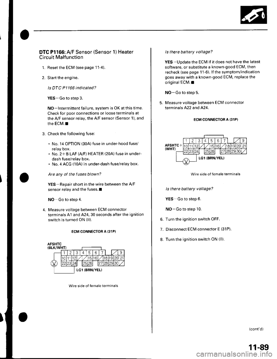
DTC Pl166: Ay'F Sensor (Sensor 1) Heater
Circuit Malfunction
1. Resetthe ECM (see page 11-4).
2. Start the engine.
ls DTC P1166 indicated?
YES-Go to step 3.
NO-lntermittent failure, system is OK at this lime.
Check for poor connections or loose terminals at
the Ay'F sensor relay, the A,/F sensor (Sensor 1), and
the EcM. !
3. Check the following fuse:
. No. 14 OPTION (30A)fuse in under-hood fuse/
reray Dox.. No. 2*B LAF (Ay'F) HEATER (20A) fuse in under-
dash fuse/relay box.. No. 4 ACG (10A) in underdash fuse/relay box.
Are any of the fuses blown?
YES Repair short in the wire between the Ay'F
sensor relay and the fuses.I
NO Go to step 4.
4. Measure voltage between ECM connector
terminals A1 and A24. 30 seconds after the ignition
switch is turned ON (ll).
ECM CONNECTOR A I31P)
Wire srde of lemale terminals
Is therc battery voltage?
YES-Update the ECM if it does not have the latest
soflware, or substitute a known-good ECM. then
recheck (see page 1 1-6). lf the symptom/indication
goes away with a known-good ECM, replace the
original ECM.I
NO-Go to step 5.
5. Measure voltage between ECM connector
terminals A22 and A24.
ECM CONNECTOR A {31P}
Wire side of female terminals
ls there battery voltage?
YES Go to step 6.
NO-Go to step 10.
6. Turn the ignition switch OFF.
7. Disconnect ECM connector E (31P).
8. Turn the ignition switch ON {ll).
(cont'd)
11-89
Page 297 of 1139
PGM-FI System
DTC Troubleshooting (cont'dl
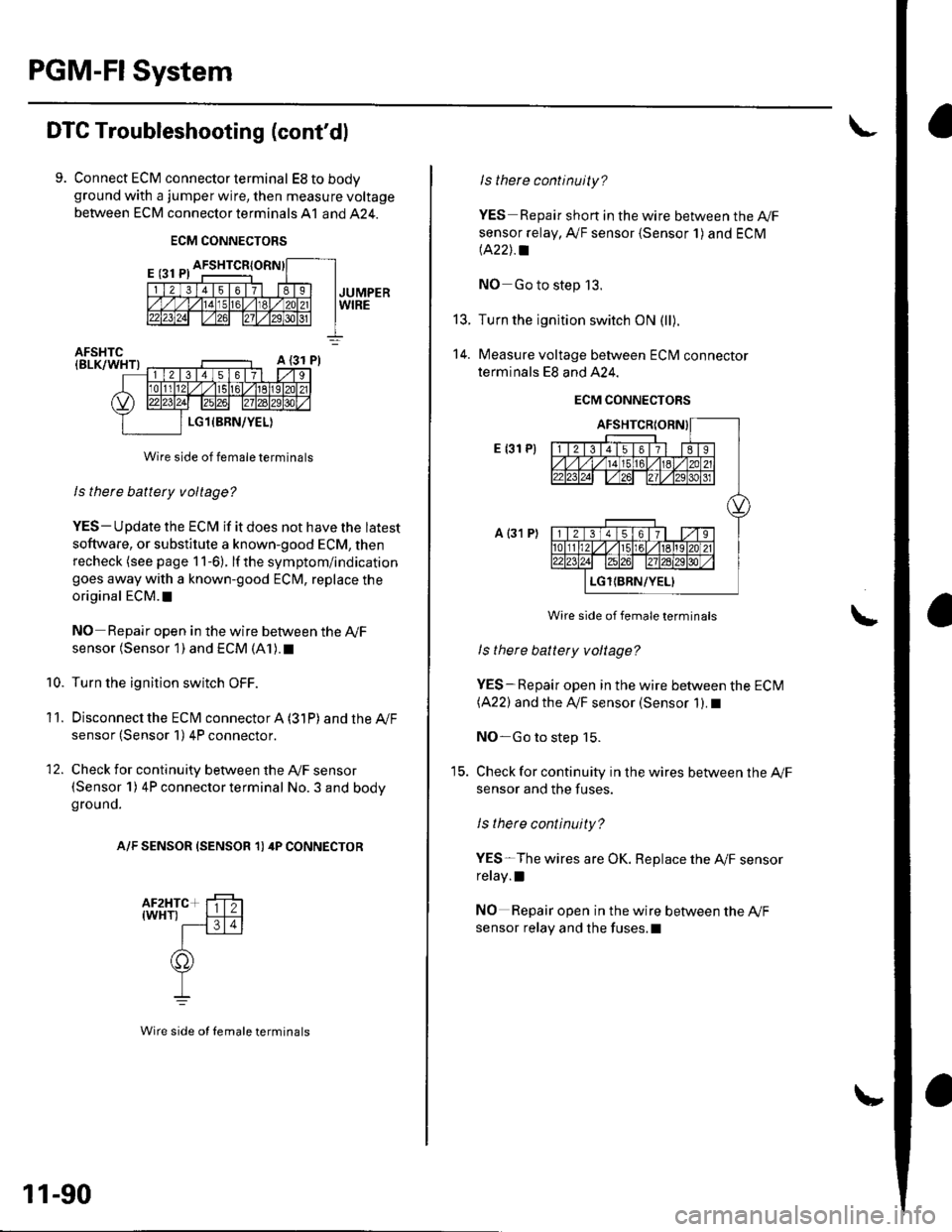
9. Connect ECM connector terminal EStobodyground with a jumper wire, then measure voltage
between ECM connector terminals A1 and 424.
ECM CONNECTORS
Wire side of female terminals
ls there battery voltage?
YES- Update the ECM if it does not have the latest
soflware, or substitute a known-good ECM, then
recheck (see page 1 1-6). lf the symptom/indication
goes away with a known-good ECM, replace the
original ECM. t
NO Repair open in the wire between the Ay'F
sensor (Sensor 1) and ECM (A1). t
Turn the ignition switch OFF.
Disconnecl the ECfM connector A (31P) and the Ay'F
sensor (Sensor 1) 4P connector.
Check for continuity between the Ay'F sensor(Sensor 1) 4P connector terminal No. 3 and bodyground.
A/F SENSOR (SENSOR 1) 4P CONNECTOR
10.
11.
12.
11-90
Wire side ot Iemale terminals
t5.
14.
ls there continuity?
YES Repair short in the wire between the A|/F
sensor relay, A,/F sensor {Sensor 1) and ECM
lA22J.a
NO Go to step 13.
Turn the ignition switch ON (ll).
Measure voltage between ECM connector
terminals E8 and A24.
ECM CONNECTORS
E {31 P)
a {31 P)
Wire side of female terminals
ls there battety voltage?
YES-Repair open in the wire between the ECM(A22) and the IVF sensor (Sensor 1). I
NO-Go to step 15.
Check for continuity in the wires between the Ay'F
sensor and the fuses.
ls there continuity?
YES-The wires are OK. Replace the A,/F sensor
relay.l
NO Repair open in the wire between the Ay'F
sensor relay and the fuses.l