clock HONDA CIVIC 2002 7.G Workshop Manual
[x] Cancel search | Manufacturer: HONDA, Model Year: 2002, Model line: CIVIC, Model: HONDA CIVIC 2002 7.GPages: 1139, PDF Size: 28.19 MB
Page 23 of 1139
L
v
2-11
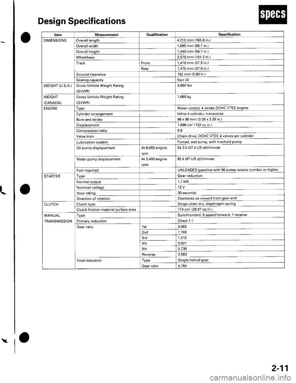
Design Specifications
O
o
o
|temMeasurementOualificationSpecilication
DIMENSIONSOveralllength4,210 mm {165.8 in.)
Overallwidth1,695 mm 166.7 in.)
Overallheight1,440 mm (56.7 in.)
2,570 mm (101.2 in.)
Trackrront1,470 mm (57.9 in.)
Rear'1,470 mm (57.9 in.i
Ground clearance152 mm (5.98 in.)
Seating capacityfour {4)
wEtGt-iT {u.s.A.)Gross Vehicle Weight Rating
(GVWR)
3,660 rbs
WEIGHT
(CANADA)
Gross Vehicle Weight Rating
{GVWR)
1,660 kg
ENGIN ETvpeWater cooled. 4 stroke DOHC V-EC engin(
Cylinder arrangementInline 4'cylinder, transverse
Bore and stroke86 x 86 mm (3.39 x 3.39 in.)
Displacement1,998 cm'(122 cu in.)
Compression ratio9.8
Valve trainChain drive. DOHC VTEC 4 valves per cylinder
Lubrication systemForced, wet sump, with trochoid pumP
Oil pump displacementAt 6,000 engine
rpm
54.3 0 (57.4 US qo/minute
Water pump displacementAt 3,400 engine82 0 (87 US qt)/minute
F!el requiredUNLEADED gasoline with 86 pump octane number or higher
STARTERTvpeGear reduction
Normaloutput
Nominalvoltage12V
Hour rating30 seconds
Direction of rotationClockwise as viewecl from gear end
CLUTCHClutch tvpeSinqle plate dry, diaphragm spring
Clutch friction material surface area174 cm'{26.97 sq in.)
I\,1AN UAL
TRANSMISSION
TvpeSvnchronized, s-speed forward, 1 reverse
Primarv reductionDirect 1:1
Gear ratiolst3.062
2nd1.769
3rd1.212
4th0.921
5th0.738
Reverse3.583
FinalreductionTypeSinole helicalgear
Gear ratio4.164
Page 44 of 1139
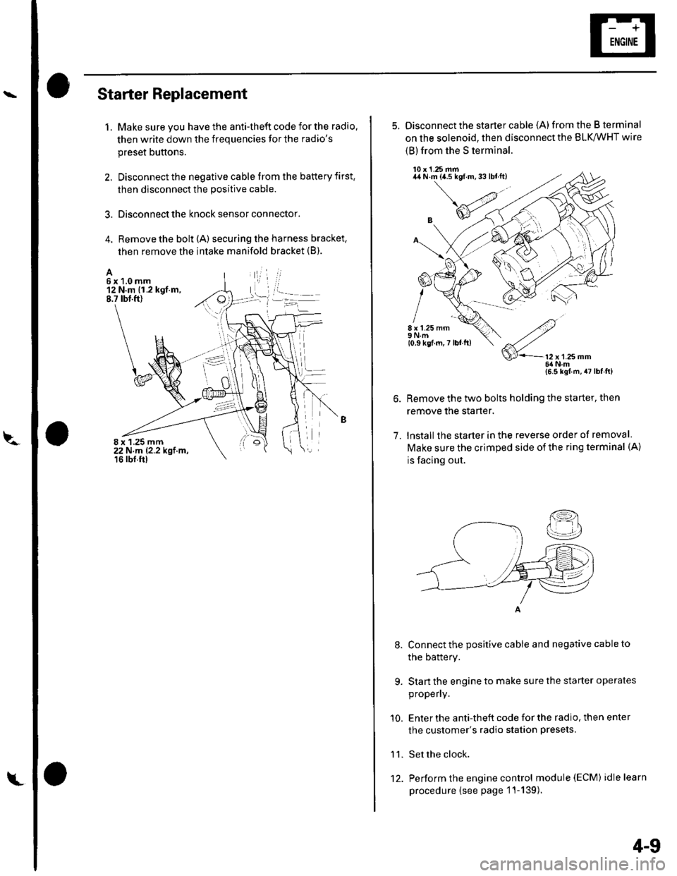
Starter Replacement
1. Make sure you have the anti-theft code for the radio.
then write down the frequencies for the radio's
preset buttons.
2. Disconnect the negative cable from the battery first,
then disconnect the positive cable.
3. Disconnect the knock sensor connector.
4. Remove the bolt (A) securing the harness bracket,
then remove the intake manifold bracket (B).
A6x1,0mm12 N.m {1.2 kgf.m,8.7 tbt.ft)
8 x 1.25 mm22 N,m 12.2 kgt.m,16 rbf.ftl
L't2.
4-9
5. Disconnect the starter cable (A)from the B terminal
on the solenoid, then disconnect the BLK,/WHT wire
{B) from the S terminal.
10 x 1.25 mm44 N.m {a.5 kgf.m,33lblft)
8 x 1.25 mm9Nm10.9 kgf.m,7 lbl ft)
7.
9.
'10.
11.
2
S'-12x12smm6ilNm{6.5 kgl m,47lbfft)
Remove the two bolts holding the starter, then
remove the starter.
lnstall the starter in the reverse order of removal.
Make sure the crimped side of the ring terminal (A)
is facing out.
Connect the positive cable and negative cable to
the batterY.
Start the engine to make sure the starter operates
propeny.
Enter the anti-theft code for the radio, then enter
the customer's radio station presets.
Set the clock.
Perform the engine control module (EcM) idle learn
procedure (see page 1 '1- 139 ).
I
Page 64 of 1139
l\-Alternator Replacement
1. Make sure you have the anti-theft code for the radio,
then write down the frequencies for the radio'spreset buttons,
2. Disconnect the negative cable from the battery first,
then disconnect the positive cable.
3. Remove the front bumper (see page 20-85).
4. Remove the right side headlight (see page 22-79).
5. Remove the reserve tank from the bracket.
6. Remove the drive belt (see page 4-26).
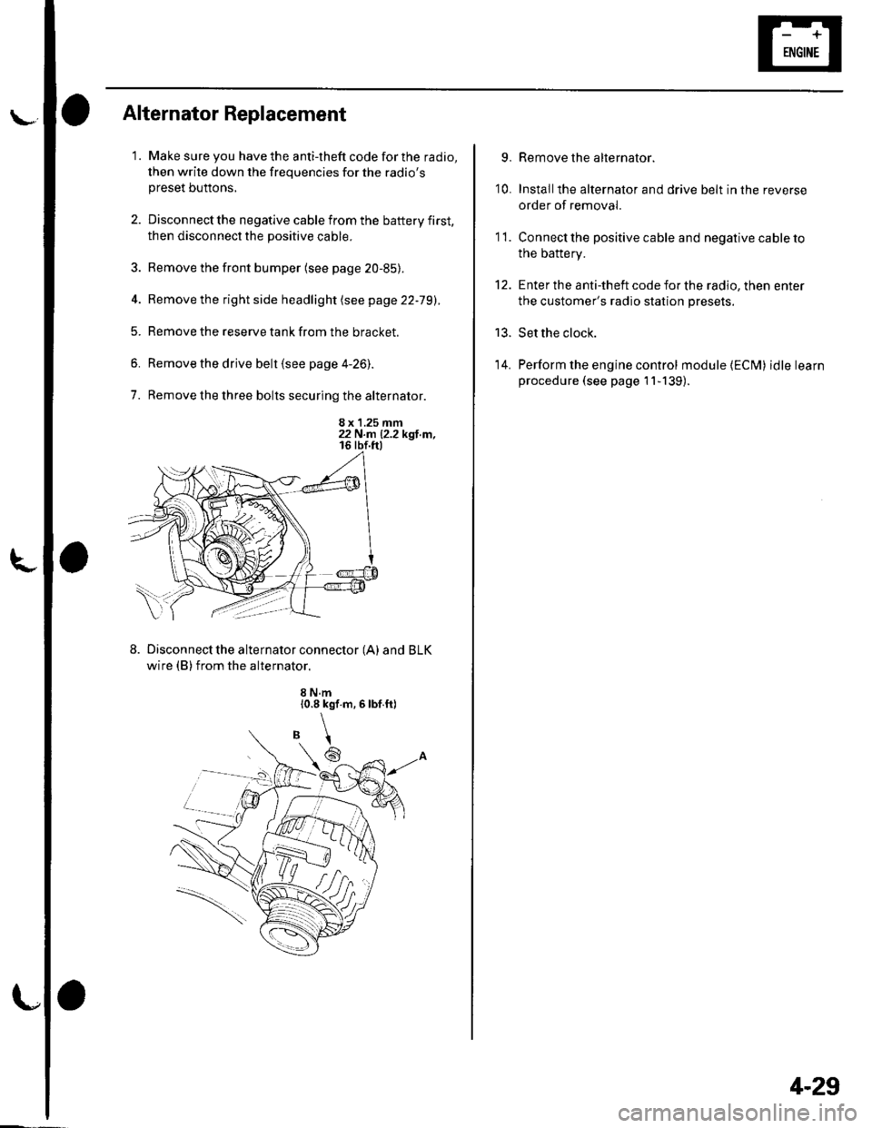
7. Remove the three bolts securing the alternator.
8 x 1.25 mm22 N.n 12.2 kgl.m,
Disconnect the alternator connector (A) and BLK
wire (B) from the alternator.
8 N.m10.8 kgf.m,6lbf.ft)
\
6
'I 1.
9.
10.
13.
14.
Remove the alternator.
Installthe alternator and drive belt in the reverse
order of removal.
Connect the positive cable and negative cable to
the battery.
Enter the anti-theft code for the radio, then enter
the customer's radio station presets.
Set the clock.
Perform the engine control module {ECM) idle learn
procedure (see page 11-139).
tt.
4-29
Page 95 of 1139
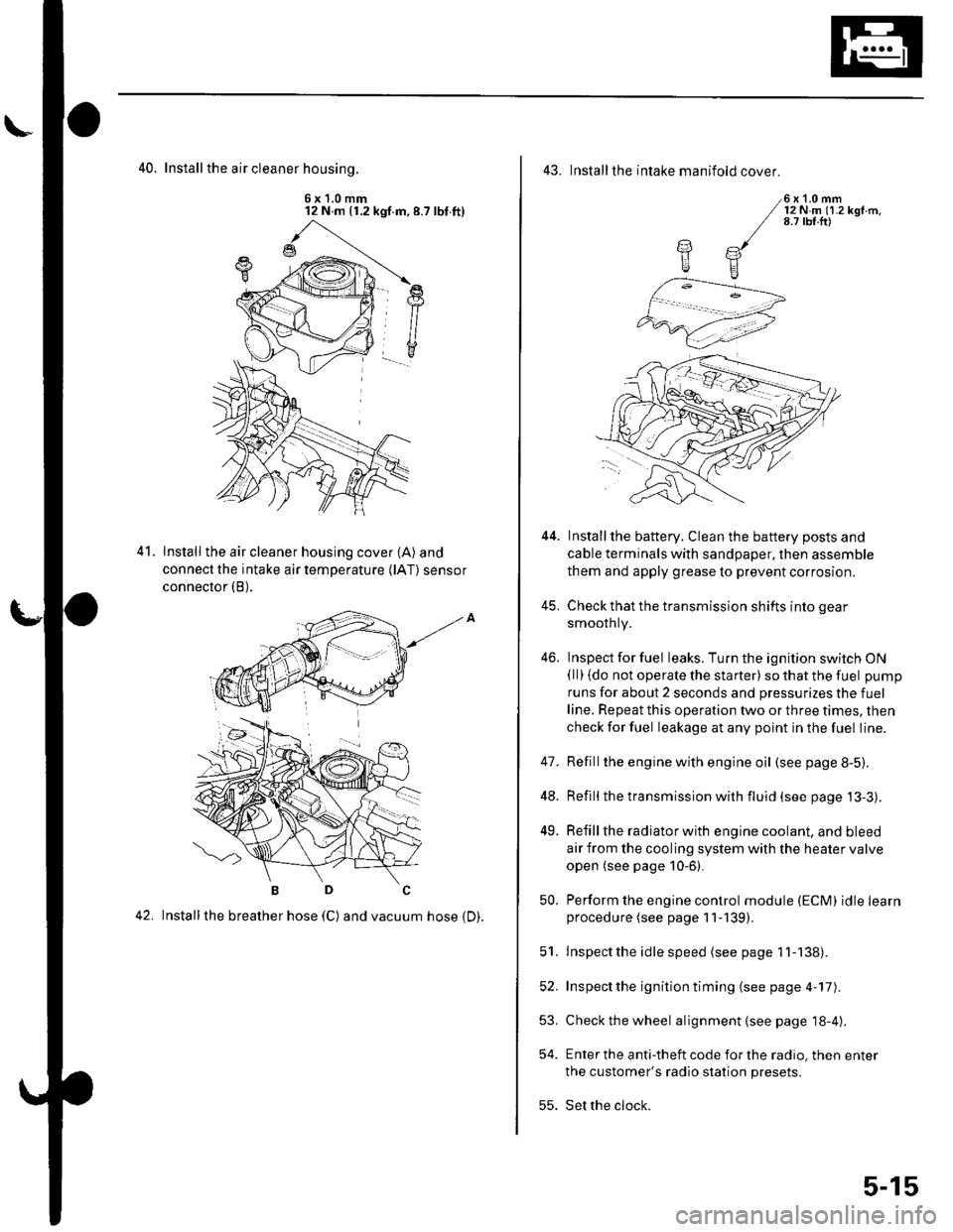
40. Install the air cleaner housinq.
6x1.0mm12 N m (1.2 kgf.m,8.7 lbt.ft)
Install the air cleaner housing cover (A) and
connect the intake air temperature (lAT) sensor
connector (B),
42. Installthe breather hose (C) and vacuum hose 1D).
41.
43. Installthe intake manifold cover.
6x1.0mm12Nm11.2kgf.m.8.7 tbf.ft)
Installthe battery. Clean the battery posts and
cable terminals with sandpaper, then assemble
them and apply grease to prevent corrosion.
Check that the transmission shifts into gear
smoothly.
Inspect for fuel leaks. Turn the ignition switch ON(ll) {do not operate the starter) so that the fuel pump
runs for about 2 seconds and pressurizes the fuel
line. Repeat this operation two or three times, then
check for fuel leakage at any point in the fuel line.
Refillthe engine with engine oil (see page 8-5).
Refill the transmission with fluid (see page 13-3).
Refill the radiator with engine coolant, and bleed
air from the cooling system with the heater valve
open (see page 10-6).
Perform the engine control module (ECM) idle learnprocedure (see page 11-139).
Inspect the idle speed (see page 1 1-138).
Inspect the ignition timing (see page 4-17).
Check the wheel alignment {see page 18-4).
Enter the anti-theft code for the radio, then enter
the customer's radio station presets.
Set the clock.
YE
44.
41.
]tE
46.
48.
49.
52.
53.
54.
50.
51.
55.
5-15
Page 103 of 1139
Cylinder Head
WEC Rocker Arms Test (cont'dl
'10. Loosen the valve on the regulator, and apply thespecified air pressure.
Specified air pressure:
290 kPa 13.0 kgt/cm', 42 psi)
NOTE: lf the synchronizing piston does not moveafter applying air pressure; move the primary orsecondary rocker arm up and down manually byrotating the crankshaft clockwise.
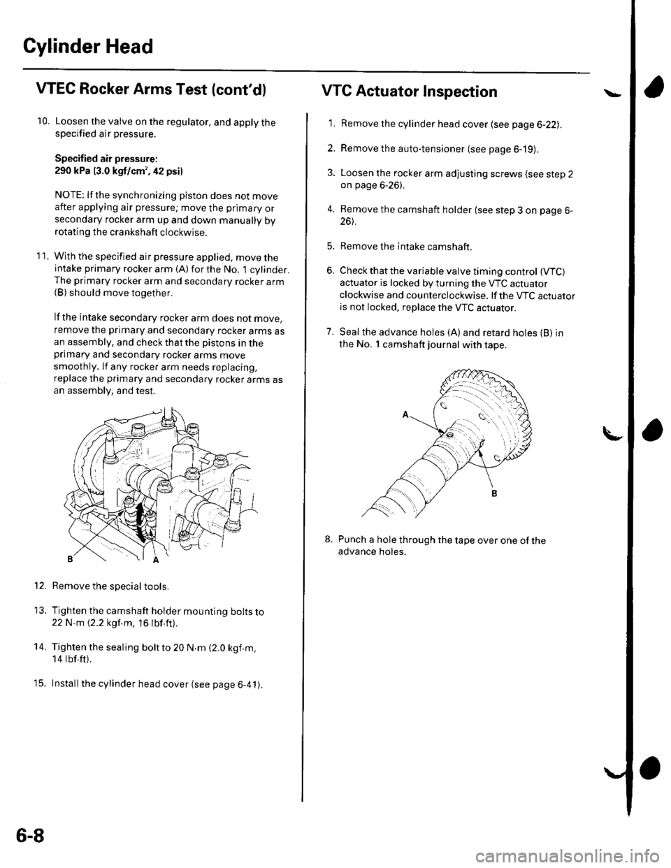
11. With the specified air pressure applied, move theintake primary rocker arm (A)forthe No, 1 cylinder.The primary rocker arm and secondary rocker arm(B) should move together.
lf the intake secondary rocker arm does not move,
remove the primary and secondary rocker arms asan assembly, and check that the pistons in theprimary and secondary rocker arms move
smoothly. lf any rocker arm needs replacing,
replace the primary and secondary rocker arms asan assembly, and test.
Remove the special tools.
Tighten the camshaft holder mounting bolts lo22N m 12.2 kgf.m, 16 lbf.ft).
Tighten the sealing boltto 20 N.m (2.0 kgf.m,
14 tbf.ft).
Installthe cylinder head cover (see page 6-41).
12.
13.
14.
t5.
6-8
VTG Actuator Inspection
'11. Remove the cylinder head cover (see page 6-22lr.
2. Remove the auto-tensioner (see page 6-19).
3. Loosen the rocker arm adjusting screws lsee step 2on page 6-26).
4. Remove the camshaft holder (see step 3 on page 6-
26t.
5. Remove the intake camshaft.
6, Check that the variable valve timing control (VTC)
actuator is locked by turning the VTC actuator
clockwise and counterclockwise. lf the VTC actuatoris not locked, replace the VTC actuator.
7. Seal the advance holes (A)and retard holes (B) in
the No. 1 camshaft journal with tape.
Punch a hole through the tape over one of theadvance holes.
Page 105 of 1139
Gylinder Head
IValve Clearance Adjustment (cont'd)
3. Select the correct thickness feeler gauge for the
valves you're going to check.
Intake: 0.21 0.25 mm (0.008-0.010 in.)
Exhaust; 0.28 0.32 mm (0.011 0.013 in.)
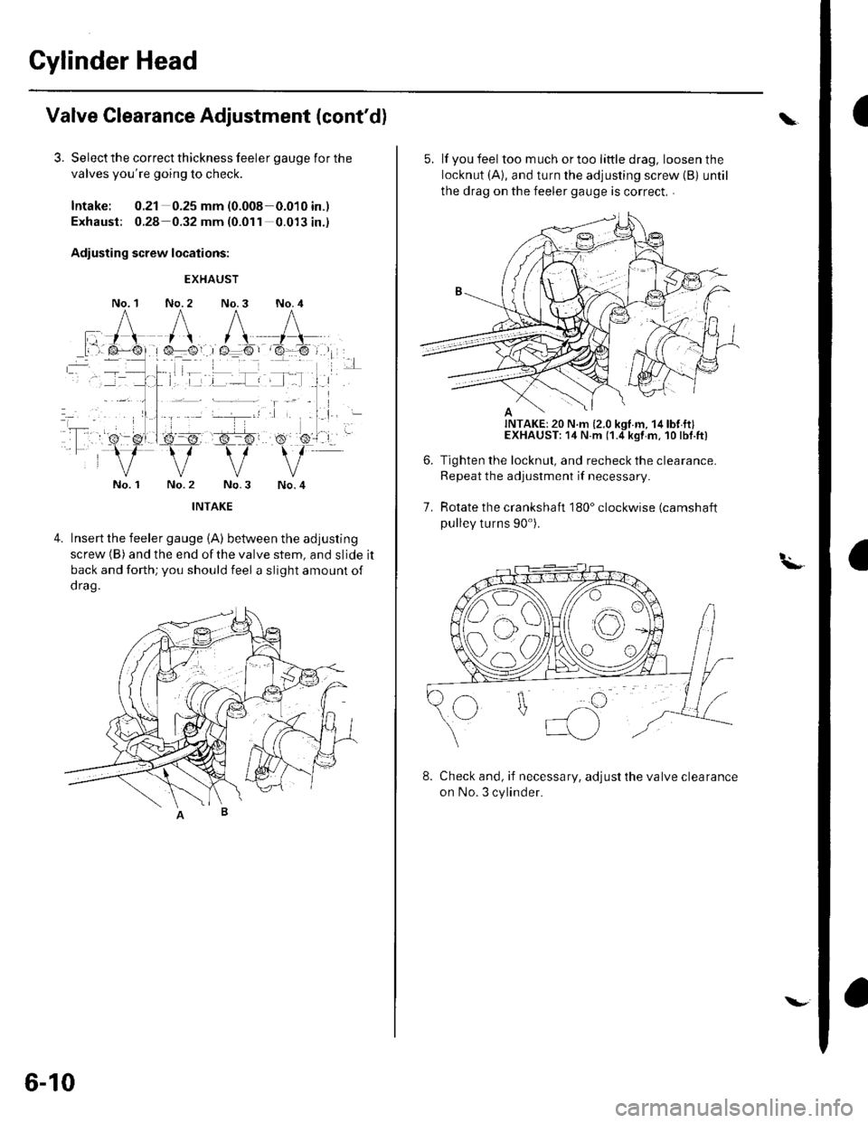
Adiusting screw locations:
No. 1
EXHAUST
No. 2 No.3 No. 4
No. 1No.4
4.Insert the feeler gauge {A) between the adjusting
screw (B) and the end ofthe valve stem, and slide it
back and forth; you should feel a slight amount of
d rag.
6-10
\.
5. lf you feel toomuchortoolittledrag, loosenthe
locknut (A), and turn the adjusting screw {B) until
the drag on the feeler gauge is correct. .
Tighten the locknut, and recheck the clearance.
Repeat the adjustment if necessary
Rotate the crankshaft 180" clockwise (camshaft
pulley turns 90').
7.
t.\-
8. Check and, if necessary, adjust the valve clearance
on No. 3 cylinder.
Page 106 of 1139
10.
9. Rotate the crankshaft 180" clockwise (camshaft
pullev turns 90').
Check and, if necessary, adjust the valve clearance
on No.4 cylinder.
Rotate the crankshaft 180" clockwise (camshaft
pulley turns 90").
Check and, if necessary, adjust the valve clearance
on No. 2 cylinder.
Install the cylinder head cover (see page 6-41).
11.
12.
Crankshaft Pulley Removal and
Installation
Special Tools Required. Holder handle 07JAB-001020A. Holder attachment, 50 mm 07NAB-001040A. Socket, 19 mm 07JAA-001020,4 or a commercially
available 19 mm socket
Removal
1. Remove front tires/wheels.
2. Remove the splash shield (see step 23 on page 5-5).
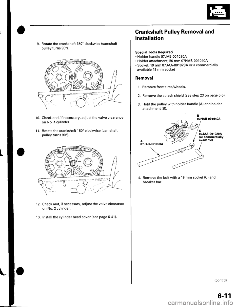
3. Hold the pulley with holder handle (A) andholder
attachment (B).
B07NAB-001040A
el
/ Srroo.oo,oroo/ (or commercially
f available)
/
Remove the bolt with a 19 mm socket (C) and
breaker bar.
(cont'd)
6-11
Page 109 of 1139
Cylinder Head
14.
Cam Chain Removal (cont'd)
Loosely install the crankshaft pulley.
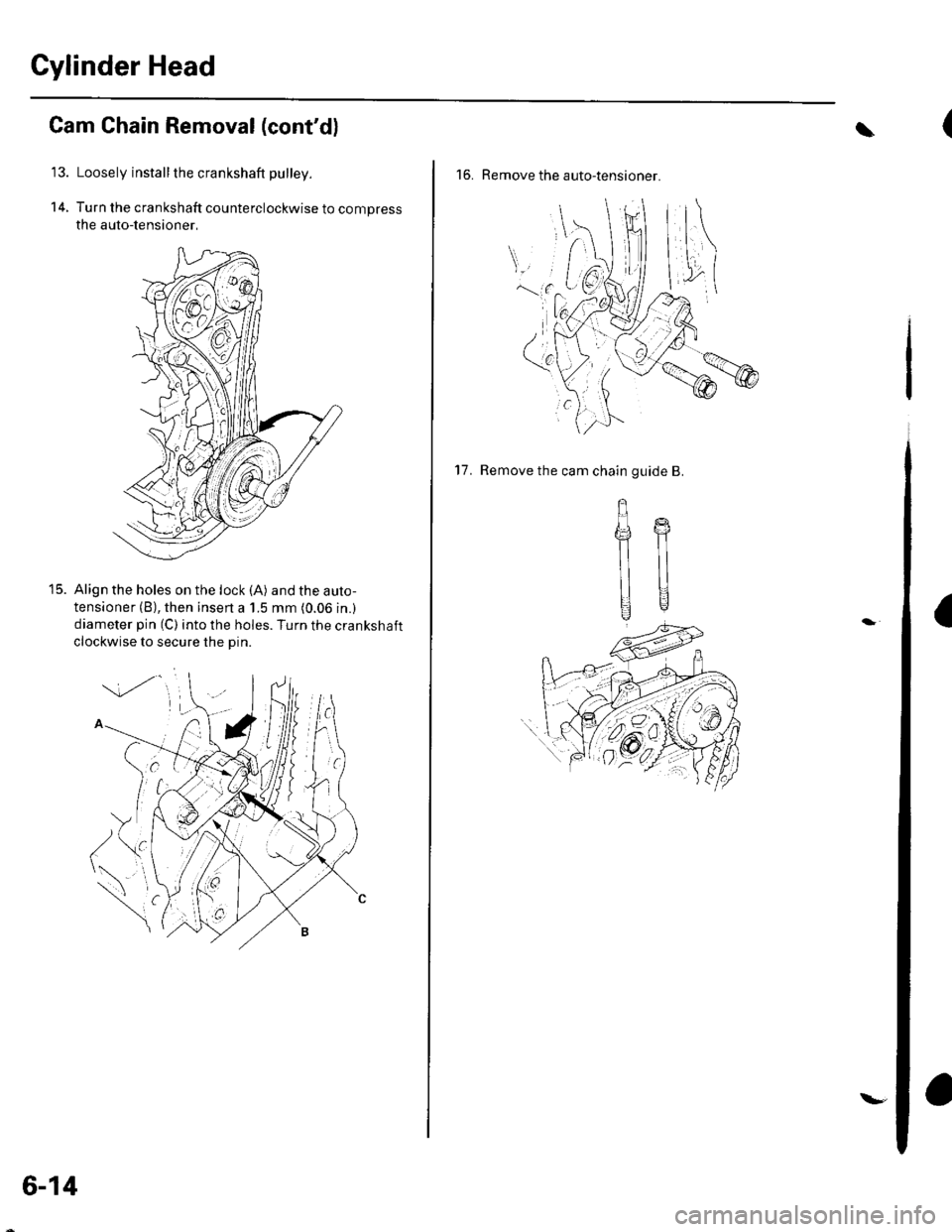
Turn the crankshaft counterclockwise to compress
the auto-lensioner,
Align the holes on the lock (A) and the auto-
tensioner (B), then insen a 1.5 mm (0.06 in.)
diameter pin (C) into the holes. Turn the crankshaft
clockwise to secure the Din.
t5.
6-14
\-
(\
16. Remove the auto-tensioner.
a
17. Remove the cam chain guide B.
gffi
llll
UU
Page 114 of 1139
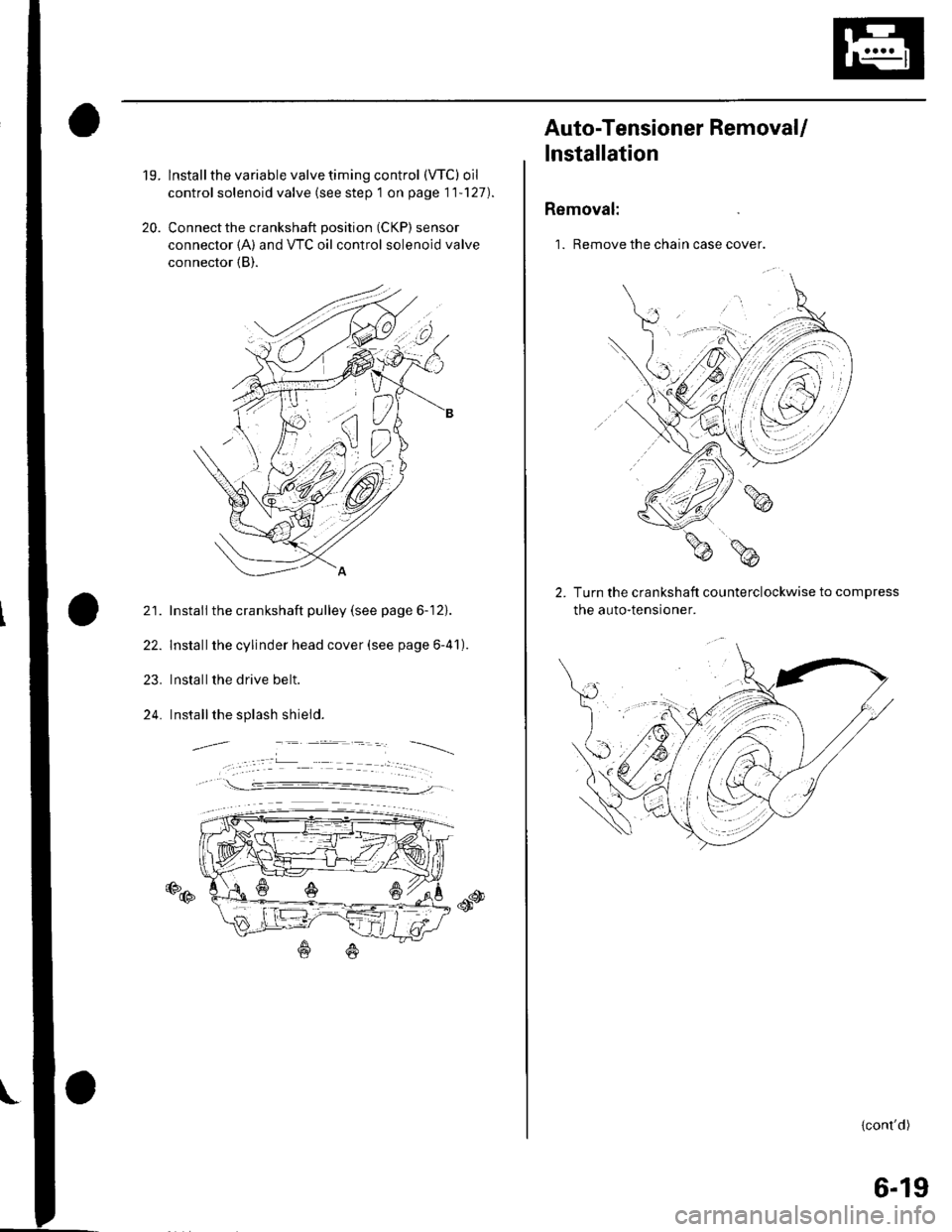
19.
20.
lnstall the variable valve timing control (VTC) oil
control solenoid valve (see step 1 on page 11'127).
Connect the crankshaft position (CKP) sensor
connector {A) and VTC oil control solenoid valve
connector (B).
21. Install the crankshaft pulley (see page 6-12).
22. Installthe cylinder head cover (see page 6-41).
23. Installthe drive belt.
24. Installthe splash shield.
€D@
Auto-Tensioner RemovaU
lnstallation
Removal:
1. Remove the chain case cover.
Turn the crankshaft counterclockwise to compress
the auto-tensroner.
{cont'd)
6-19
Page 115 of 1139
Gylinder Head
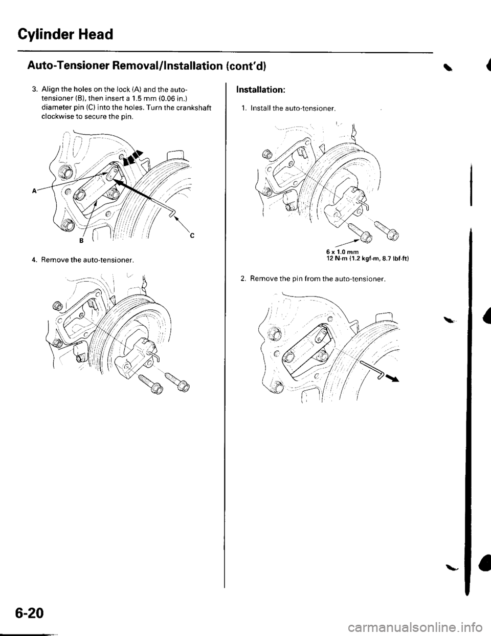
Auto-Tensioner Removal/l nstallation
3. Align the holes on the lock (A) and the auto-
tensioner (B), then insert a 1.5 mm (0.06 in.)
diameter pin (C) into the holes. Turn the crankshaft
clockwise to secure the oin.
4. Remove the auto-tensioner.
6-20
\-
(cont'dl
Installation:
1. Install the auto-tensioner.
\
6x1.0mm12 N.m {1.2 kgt.m, 8.7 lbt.tt)
Remove the pin from the auto-tensioner.
a\