HONDA CIVIC 2002 7.G Workshop Manual
Manufacturer: HONDA, Model Year: 2002, Model line: CIVIC, Model: HONDA CIVIC 2002 7.GPages: 1139, PDF Size: 28.19 MB
Page 811 of 1139
Heating and Air Gonditioning
Blower Unit Removal and Installation {cont'd}
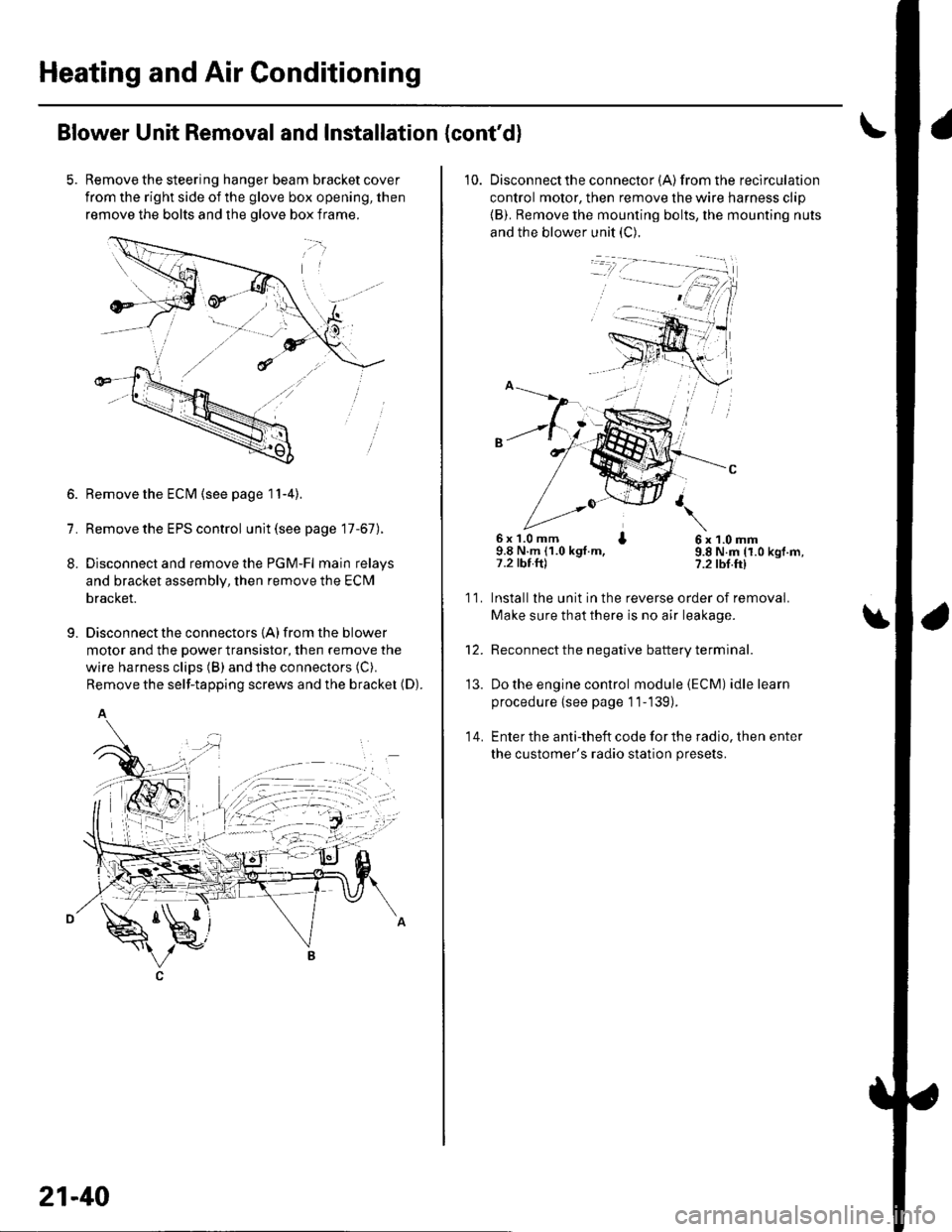
Remove the steering hanger beam bracket cover
from the right side of the glove box opening, then
remove the bolts and the olove box frame.
1.
8.
9.
Remove the ECM (see page 11-4).
Remove the EPS control unit (see page 17-67).
Disconnect and remove the PGM-Fl main relays
and bracket assembly, then remove the ECM
bracket.
Disconnect the connectors {A) from the blower
motor and the power transistor, then remove the
wire harness clips (B) and the connectors (C).
Remove the self-tapping screws and the bracket (D).
A
21-40
10. Disconnectthe connector {A) from the recirculation
control motor, then remove the wire harness clip
{B). Remove the mounting bolts, the mounting nuts
and the blower unit (C).
6x 1.0 mm I9.8 N.m (1.0 kgt.m,7.2 tbt.ftl
6x1.0mm9.8 N.m (1.0 kgf.m,?.2 tbf.ft)
11.
14.
Installlhe unit in the reverse order of removal.
Make sure that there is no air leakage.
Reconnect the negative battery terminal.
Do the engine control module (ECM) idle learn
procedure {see page 11-139).
Enter the anti-theft code for the radio, then enter
the customer's radio station presets.
\
'13.
Page 812 of 1139
Blower Unit Components Replacement
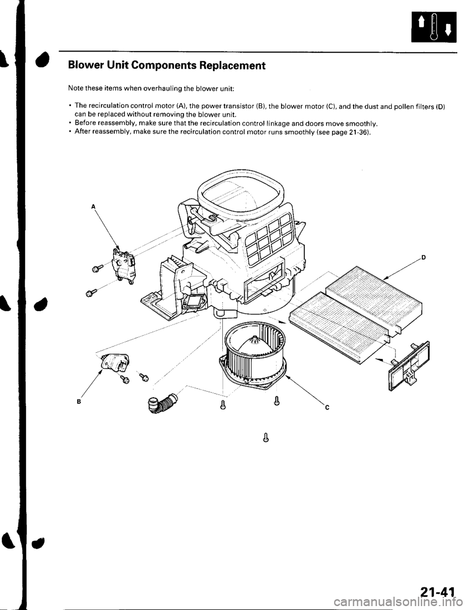
Nole these items when overhauling the blower unit;
' The recirculation control motor (A), the power transistor (B), the blower motor (C), and the dust and pollen filtefs (D)
can be replaced without removing the blower unit.. Before reassembly, make surethatthe recirculation control linkage and doors move smoothly.. After reassembly, make surethe recirculation control motorruns smoothly (see page 2j-36).
A
21-41
Page 813 of 1139
Heating and Air Gonditioning
a
1.
Evaporator Core Replacement
Recover the refrigerant with a recovery/recycling/
charging station (see page 21-53).
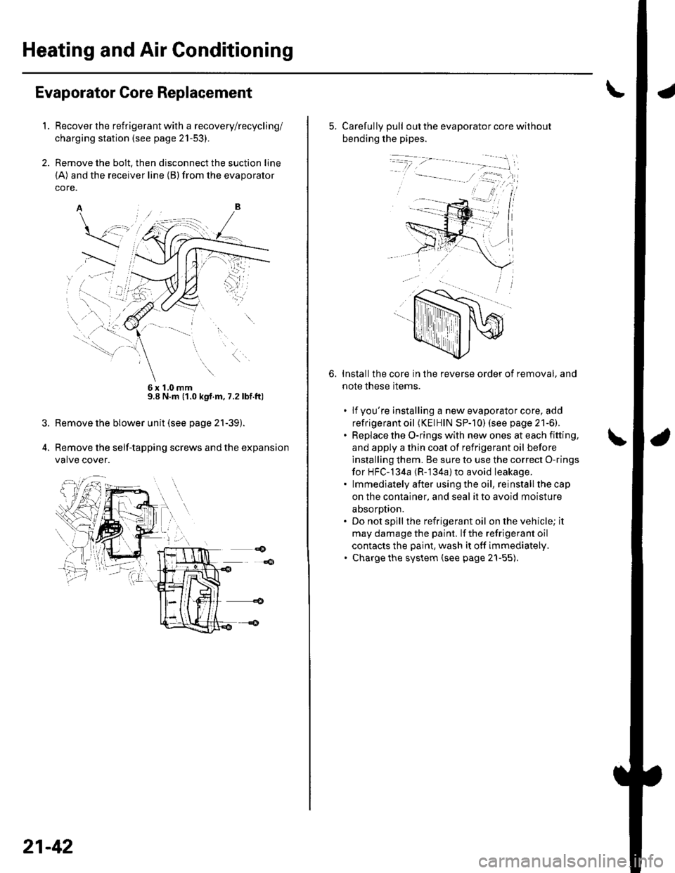
Remove the bolt, then disconnect the suction line
(A) and the receiver line (B)from the evaporator
core.
6x10mm9.8 N.m (1.0 kgt.m, 7.2lbf.ft)
Remove the blower unit (see page 21-39).
Remove the self-tapping screws and the expansion
valve cover.
21-42
5. Carefully pull out the evaporator core without
bending the pipes.
Installthe core in the reverse order of removal, and
note these items.
. lfyou're installing a new evaporator core, add
refrigerant oil (KElHlN SP-]0) (see page 21-6).. Replace the O-rings with new ones at each fitting,
and apply a thin coat of refrigerant oil before
installing them. Be sure to use the correct O-rings
for HFC-134a (R-'134a) to avoid leakage.. lmmediatelyafter usingthe oil, reinstallthecap
on the container, and seal it to avoid moisture
absorotion.. Do not spill the refrigerant oil on the vehicle; it
may damage the paint. lf the refrigerant oil
contacts the paint, wash it off immediately.. Charge the system (see page 21-55).
6.
Page 814 of 1139
Heater Unit/Core Replacement
SRS components are located in this area. Review the
SRS component locations (see page 23'13), and
precautions and procedures (see page 23-14) in the SRS
section before performing repairs or service.
1. Make sure you have the anti-theft code forthe radio,
then write down the freouencies for the radio's
Dreset buttons.
4.
Disconnect the negative cable from the battery,
Disconnect the suction and receiver lines from the
evaporator core (see page 21-42).
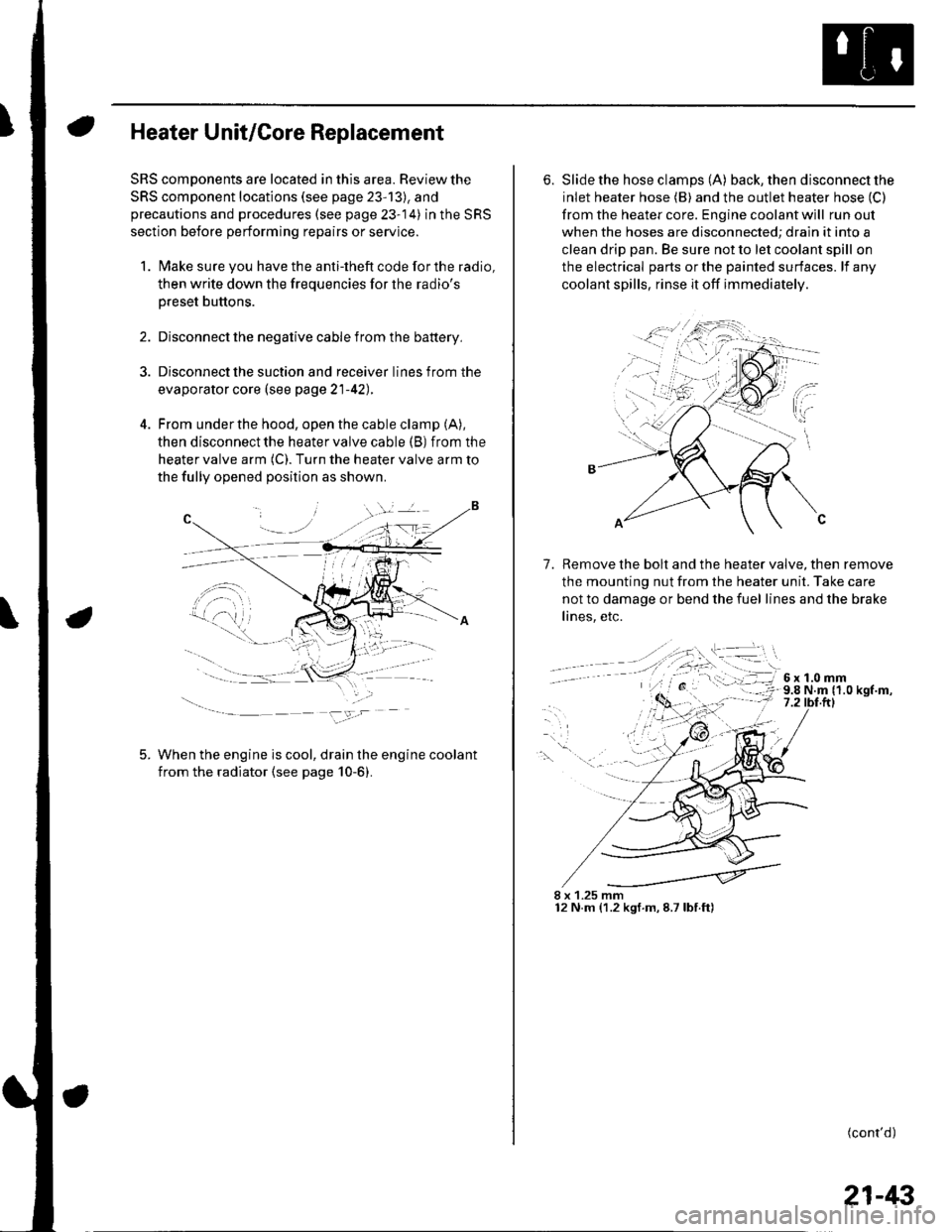
From under the hood, open the cable clamp (A),
then disconnect the heater valve cable (B) from the
heater valve arm (C). Turn the heater valve arm to
the fully opened position as shown
When the engine is cool, drain the engine coolant
from the radiator (see page 10-6).
6. Slide the hose clamps (A) back, the n d isconnect the
inlet heater hose (B) and the outlet heater hose (C)
from the heater core. Engine coolant will run out
when the hoses are disconnected; drain it into a
clean drip pan. Be sure not to let coolant spill on
the electrical parts or the painted surfaces. lf any
coolant spills, rinse it off immediately.
Remove the bolt and the heater valve, then remove
the mounting nut from the heater unit. Take care
not to damage or bend the fuel lines and the brake
lines, etc.
7.
8 x 1.25 mm12 N.m (1.2 kgf.m,8.7lbf.ft)
(cont'd)
21-43
Page 815 of 1139
Heating and Air Conditioning
Heater Unit/Core Replacement (cont'd)
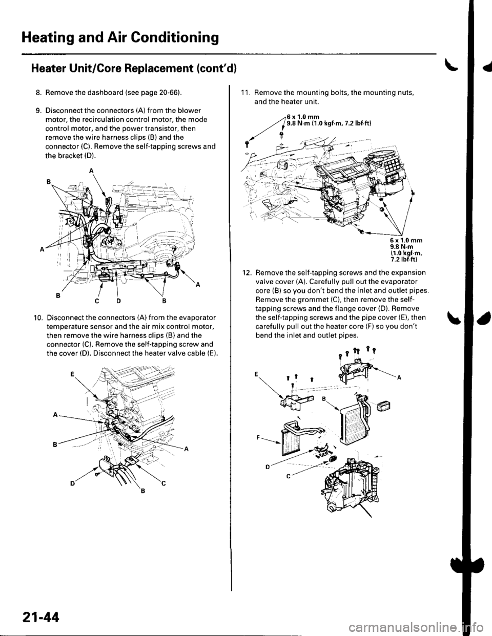
8. Remove the dashboard {see page 20-66).
9. Disconnectthe connectors (A) from the blower
motor, the recirculation control motor, the mode
control motor, and the power transistor, then
remove the wire harness clips (B) and the
connector (C). Remove the self-tapping screws and
the bracket (D).
Disconnect the connectors (A) from the evaporator
temperature sensor and the air mix control motor,
then remove the wire harness clips (B) and the
connector (C). Remove the self-tapping screw and
the cover (D). Disconnect the heater valve cable (E).
10,
7t,
21-44
11. Remove the mounting bolts, the mounting nuts,
and the heater unit.
Remove the self-tapping screws and the expansion
valve cover (A). Carefully pull out the evaporator
core (B) so you don't bend the inlet and outlet pipes.
Remove the grommet (C), then remove the self-
tapping screws and the flange cover (D). Bemove
the self-tapping screws and the pipe cover (E), then
carefully pull out the heater core (F) so you don't
bend the inlet and outlet oioes.
@
5x 1.0 mm9.8 N.m11.0 kgl m,7.2 tbf.ftl
12.
Page 816 of 1139
13. Installthe heater core and the evaporator core in
the reverse order of removal.
14. Installthe heater unit in the reverse order of
removal, and note these items:
. Do not interchange the inlet and outlet heater
hoses, and installthe hose clamps securely.. Refillthe cooling system with engine coolant (see
page 10-6).. Adjust the heater valve cable (see page 2'l-461.. Make sure that there is no coolant leakage.. Make sure that there is no air leakage.. Refer to evaporator core replacement {see step 6
on page 21-42).. Do the engine control module (ECl\4) idle learn
procedure (see page 11-139).. Enter the anti-theft code for the radio, then enter
the customer's radio station Dresets.
21-45
Page 817 of 1139
Heating and Air Conditioning
Heater Valve Cable Adjustment
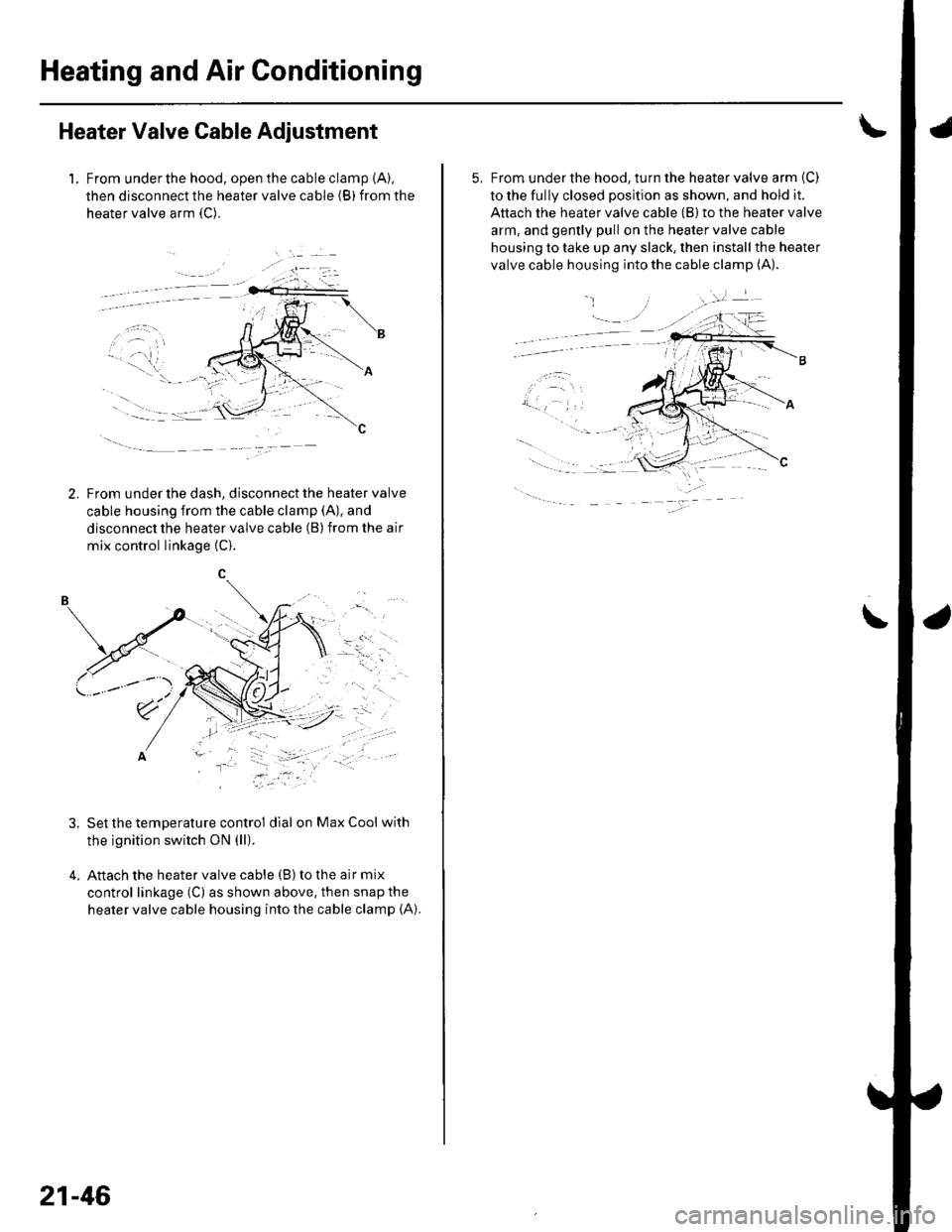
1. From underthe hood, open the cable clamp {A),
then disconnect the heater valve cable (B) from the
heater valve arm {C).
tFrom under the dash, disconnect the heater valve
cable housing from the cable clamp (A), and
disconnect the heater valve cable (B) from the air
mix control linkage {C).
, t.- l
\'r2t' ''' '
' ::"'
Set the temperature control dial on Max Cool with
the ignition switch ON (ll).
Attach the heater valve cable (B) to the air mix
control linkage (C) as shown above, then snap the
heater valve cable housing into the cable clamp (A).
.'.-:',,
-"ll
.....-
21-46
5, From under the hood, turn the heater valve arm {C)
to the fully closed position as shown, and hold it.
Attach the heater valve cable (B) to the heater valve
arm, and gently pull on the heater valve cable
housing to take up any slack, then install the heater
valve cable housing into the cable clamp (A).
.
\
Page 818 of 1139
Compressor Replacement
1. lf the compressor is marginally operable, run the
engine at idle speed, and let the air conditioning
work for a few minutes, then shut the engine off.
2. Make sure you have the anti-theft code for the radio,
then write down the frequencies for the radio's
preset buttons.
3. Disconnect the negative cable from the battery.
4. Recover the refrigerant with a recovery/recycling/
charging station (see page 21-53).
5. Remove the alternator (see page 4-29).
6. Remove the Ay'C condenser fan assembly (see page
10-10).
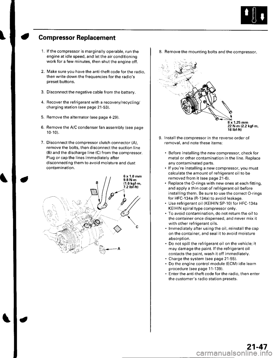
7. Disconnectthe compressor clutch connector (A),
remove the bolts, then disconnect the suction line(B) and the discharge line (C)from the compressor.
Plug or cap the lines immediately after
disconnecting them to avoid moisture and dust
contamination.
6 x '1.0 mm9.8 N.m11.0 kgt.m,7.2 tbl.ttl
u1/
(
o
8. Remove the mounting bolts and the compressor.
8 x 1.25 mm22 N.m 12.2 kgf.m.
9. Installthe compressor in the reverse order of
removal, and note these items:
. Before installing the new compressor, check for
metal or other contamination in the line. Replace
any contaminated parts.. lf you're installing a newcompressor, you must
calculate the amount of refrigerant oil to be
removed from it (see page 21-6).. Replace the O-rings with new ones at each fitting,
and apply a thin coat of refrigerant oil before
installing them. Be sure to use the correct O-rings
for HFC-134a {R-134a) to avoid leakage,. Use refrigerant oil (KElHlN SP-'10) for HFC-134a
KEIHIN spiral type compressor only.. To avoid contaminatlon, do not return the oilto
the container once dispensed, and never mix it
with other refrigerant oils.. lmmediately after using the oil, reinstallthe cap
on the container, and seal it to avoid moisture
absorption.. Do not spill the refrigerant oil on the vehicle; it
may damage the paint. lf the refrlgerant oil
contacts the paint, wash it off immediately.. Charge the system (see page 21-55).. Do the engine control module (ECM) idle learn
procedure (see page 11-'139).. Enter the antitheft code for the radio, then enter
the customer's radio station presets.
21-47
Page 819 of 1139
Heating and Air Gonditioning
1.
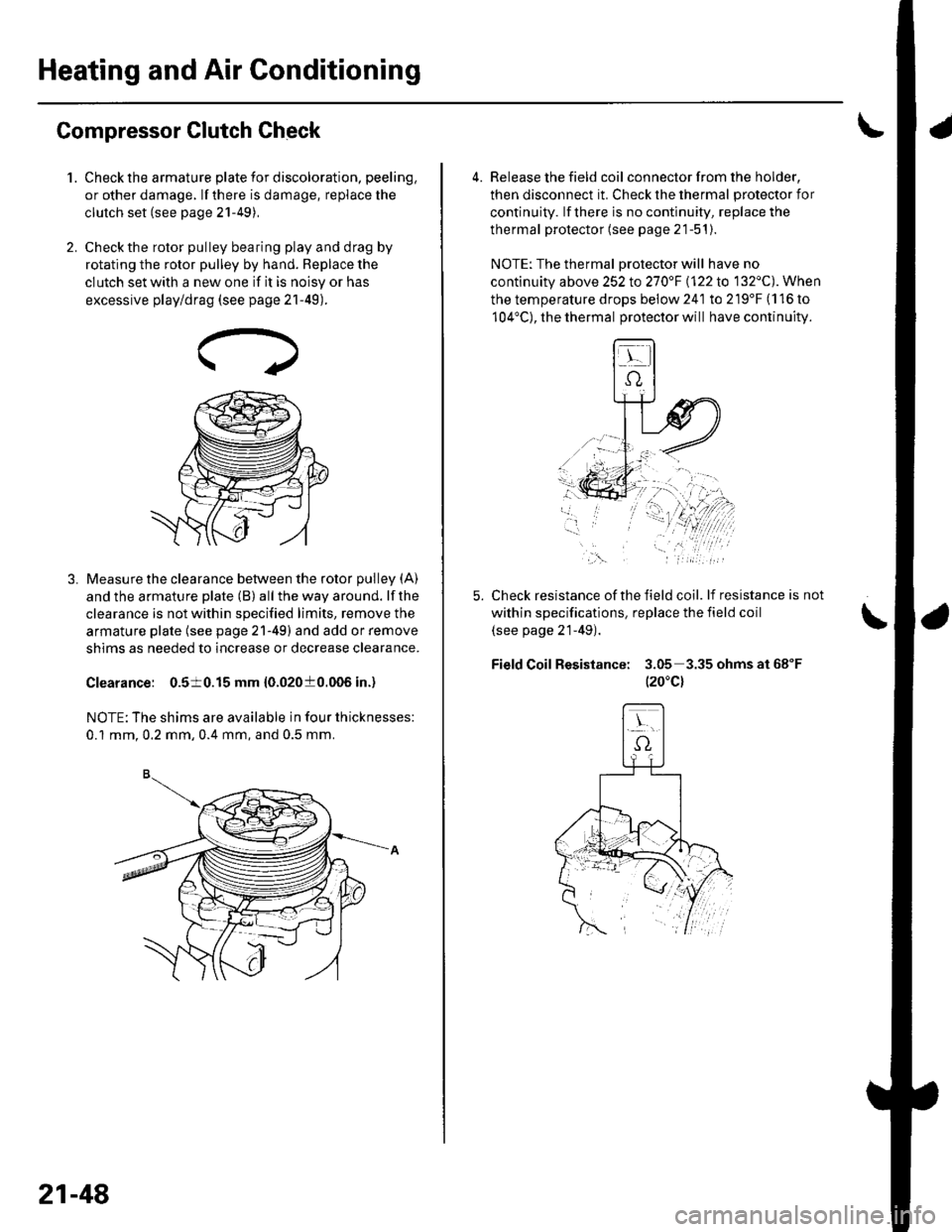
Compressor Clutch Check
Check the armature plate for discoloration, peeling,
or other damage. lf there is damage, replace the
clutch set (see page 21-49),
Check the rotor pulley bearing play and drag by
rotating the rotor pulley by hand. Beplace the
clutch set with a new one if it is noisy or has
excessive play/drag (see page 21-49).
Measure the clearance between the rotor pulley (A)
and the armature plate (B) all the way around. lf the
clearance is not within specified limits, remove the
armature plate (see page 21-49) and add or remove
shims as needed to increase or decrease clearance.
Clearance: 0.510.15 mm {0.02010.006 in.)
NOTE: The shims are available in four thicknesses:
0.1 mm.0.2 mm,0.4 mm, and 0.5 mm.
21-48
a
4. Release the field coil con nector f rom the holder,
then disconnect it. Check the thermal protector for
continuity. lf there is no continuity, replace the
thermal protector (see page 21-51).
NOTE: The thermal Drotector will have no
continuity above 252to270"F \122lo 132'C). When
the temperature drops below 241 to 219'F (116 to
104'C), the thermal protector will have continuity.
Check resistance of the field coil. lf resistance is not
within specifications, replace the field coil
(see page 21-49).
Field Coil Resistance: 3.05 3.35ohmsat68"F
t20"c)
,\.
Page 820 of 1139
Compressor Clutch Overhaul
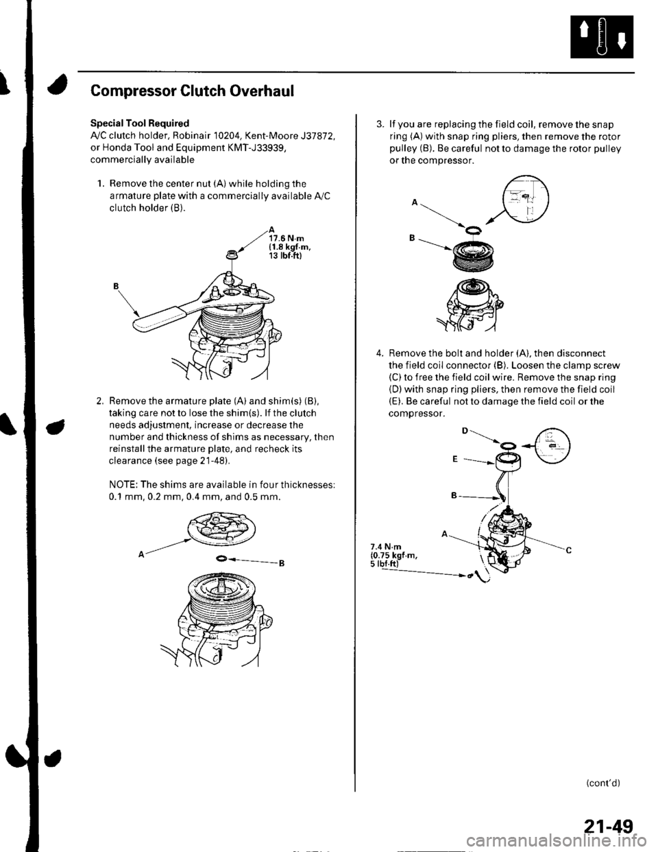
Special Tool Required
A,/C clutch holder, Robinair 10204. Kent-Moore J37872,
or Honda Tool and Equipment KMT-J33939,
commercially available
1. Remove the center nut (A) while holding the
armature plate with a commercially available A,/C
clutch holder (B).
17.6 N.m{1.8 kgf.m,13 tbt.ft)
Remove the armature plate (A) and shim(s) (B),
taking care not to lose the shim(s). lf the clutch
needs adjustment, increase or decrease the
number and thickness of shims as necessary, then
reinstallthe armature Dlate, and recheck its
clearance (see page 21-481.
NOTE: The shims are available in four thicknesses:
0.1 mm,0.2 mm,0.4 mm, and 0.5 mm.
9-=-g
3. lf you are replacing the field coil, remove the snap
ring (A) with snap ring pliers, then remove the rotor
pulley (B). Be careful not to damage the rotor pulley
or tne compressor.
4. Remove the bolt and holder (A). then disconnect
the field coil connector (B). Loosen the clamp screw(C) to iree the field coil wire. Remove the snap ring
{D)with snap ring pliers, then remove the field coil(E). Be careful not to damage the field coil or the
comoressor.
\ot
-@
/@h"
.ffi
7.4 N.m(0.75 kgf m,5 tbf.ft)---------------- ")
(cont'd)
21-49