HONDA CIVIC 2002 7.G Workshop Manual
CIVIC 2002 7.G
HONDA
HONDA
https://www.carmanualsonline.info/img/13/5744/w960_5744-0.png
HONDA CIVIC 2002 7.G Workshop Manual
Trending: turn signal bulb, fuse box, dimensions, coolant reservoir, battery location, relay, fuel additives
Page 911 of 1139
Exterior Lights
4.
5.
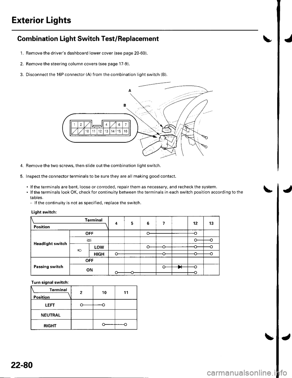
Combination Light Switch Test/Replacement
1. Remove the driver's dashboard lower cover (see page 20-60).
2. Remove the steering column covers (see page 17-9).
3, Disconnectthe l6Pconnector(A) f rom the combination light switch (B).
Remove the tlvo screws, then slide out the combination light switch.
Inspect the connector terminals to be sure they are all making good contact.
. lf the terminals are bent, loose or co rroded, repa ir them as necessa ry, a nd recheck the system..lftheterminalslookOK,checkforcontinuitybetweentheterminalsineachswitchpositionaccordingtothe
tables.- lf the continuity is not as specified, replace the switch.
Light switch:
Telmint
Position451213
Headlight switch
OFF
LOWo--
HIGHo--
Passing switch
OFF
ONo-
Turn signalswitch:
Terminal
Position21011
LEFT----o
NEUTRAL
RIGHTo--
22-80
Page 912 of 1139
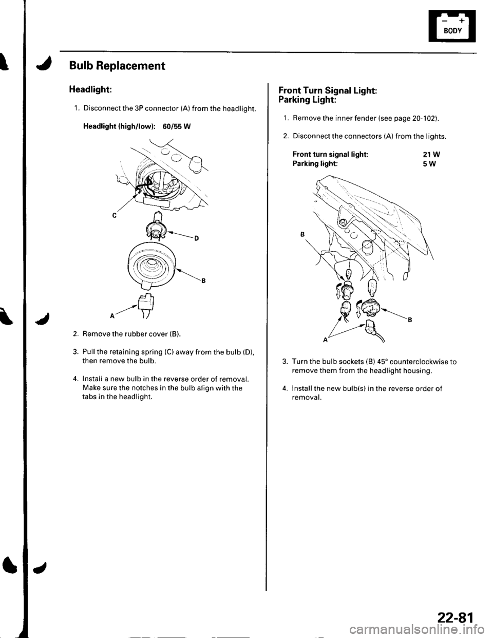
Bulb Replacement
Headlight:
1. Disconnect the 3P connector (A) from the headlight.
Headlight {high/low): 60/55 W
f-rI-'-+lA- )/
Remove the rubber cover (B).
Pull the retaining spring (C) away from the bulb (D),
then remove the bulb.
Install a new bulb in the reverse order of removal.
Make sure the notches in the bulb align with the
tabs ln the headlight.
2.
Front Turn Signal Light:
Parking Light:
1. Remove the inner fender (see page 20-102).
2. Disconnectthe connectors (A) from the lights.
21W
5W
4.
Front turn signal light:
Parking light:
Turn the bulb sockets (B) 45'counterclockwise to
remove them from the headlight housing.
Installthe new bulb(s) in the reverse order of
removat.
22-81
Page 913 of 1139
Exterior Lights
1.
2.
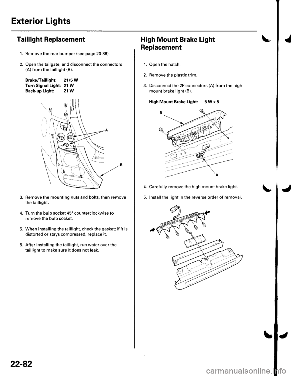
Taillight Replacement
Remove the rear bumper (see page 20-86).
Open the tailgate, and disconnect the connectors(A) from the taillight (B).
Brako/Taillight; 2115W
Turn Signal Light: 21 W
Back-up Light: 21W
Remove the mounting nuts and bolts, then remove
the taillight.
Turn the bulb socket 45' counterclockwise to
remove the bulb socket.
When installing the taillight. check the gasket; if it is
distorted or stays compressed, replace it.
After installing the taillight. run water over the
taillight to make sure it does not leak.
=\
ili--- _ \
rB , \.
---'a t
\
22-82
High Mount Brake Light
Replacement
1. Open the hatch.
2. Remove the plastic trim.
3. Disconnectthe 2P connectors (A)from the high
mount brake light (B).
High Mounl Brake Light: 5 W x 5
Carefully remove the high mount brake light.
lnstall the light in the reverse order of removal.5.
'
Page 914 of 1139
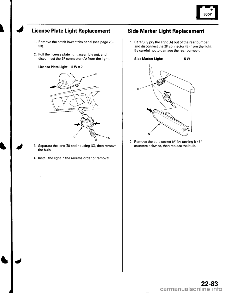
License Plate Light Replacement
1.Remove the hatch lower trim panel (see page 20-
Pullthe license plale light assembly out. and
disconnect the 2P connector (A) from the light.
License Plate Light: 5Wx2
3.
4.
'[-J^,^f , t lo \
+tiP'-t \-J'fl^
"/ \==-^
Separate the lens (B) and housing (C), then remove
the bulb.
lnstallthe light in the reverse order of removal.
Side Marker Light Replacement
1. Carefully pry the light (A) outofthe rear bumper,
and disconnect the 2P connector (B) from the light.
Be careful not to damage the rear bumper.
Side Marker Light:5W
2.Remove the bulb socket (A) by turning it 45'
counterclockwise. then reolace the bulb.
22-83
Page 915 of 1139
Exterior Lights
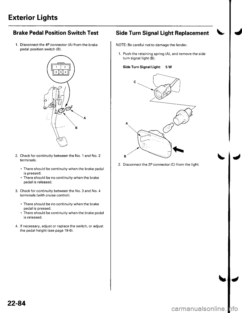
Brake PedalPosition Switch Test
1. Disconnectthe 4P connector (A) from the brakepedal position switch {B).
Check for continuity between the No. 1 and No. 2
termtnals.
. There should be continuity when the brake pedal
rs presseo.
. There should be no continuity when the brake
pedal is released.
Check for continuity between the No. 3 and No. 4
terminals {with cruise control).
There should be no continuity when the brake
pedal is pressed.
There should be continuity when the brake pedal
is released.
lf necessary, adjust or replace the switch, or adjust
the pedal height (see page 19-6).
22-84
Side Turn Signal Light Replacement
NOTE: Be careful nol to damage the fender.
1. Push the retaining spring (A). and remove the side
turn signal light (B),
Side Turn Signal Light: 5 W
2. Disconnect the 2P connector {C) from the light.
Page 916 of 1139
Turn Signal/Hazard Flasher
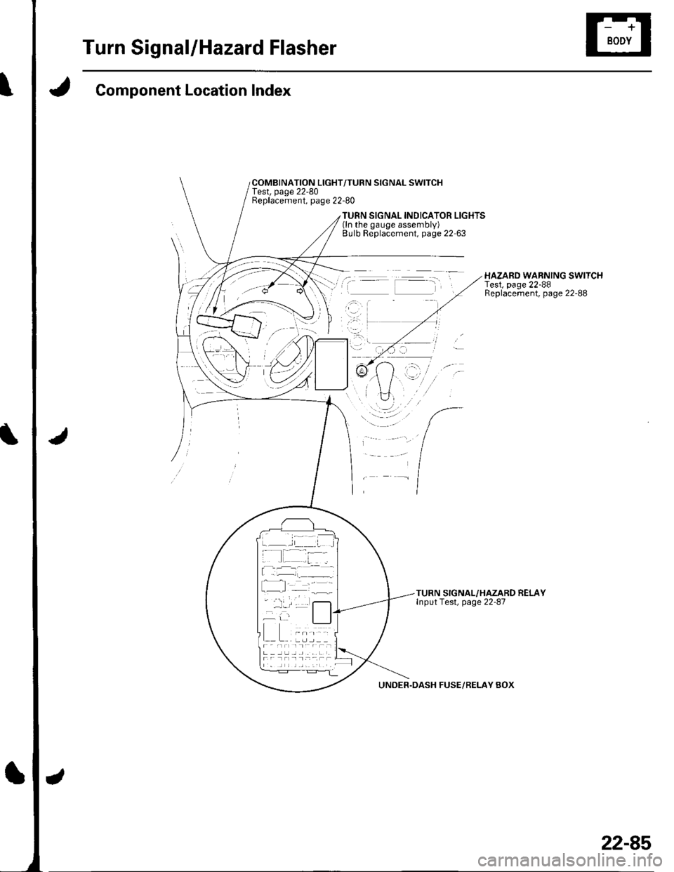
Component Location Index
COMBINATION LIGHT/TURN SIGNAL SWITCHTest, page 22-80Beplacement, page 22-80
TURN SIGNAL INDICATOR LIGHTS(ln the gauge assembly)Bulb Replacement, page 22'63
HAZARD WARNING SWITCHTest, page 22-88Replacement, page 22-88
TURN SIGNAL/HAZARD RELAYInput Test, page 22-87
UNDER.DASH FUSE/RELAY BOX
22-85
Page 917 of 1139
Turn Signal/Hazard Flasher
UNDff HOOD FUSUftIIY 8OX
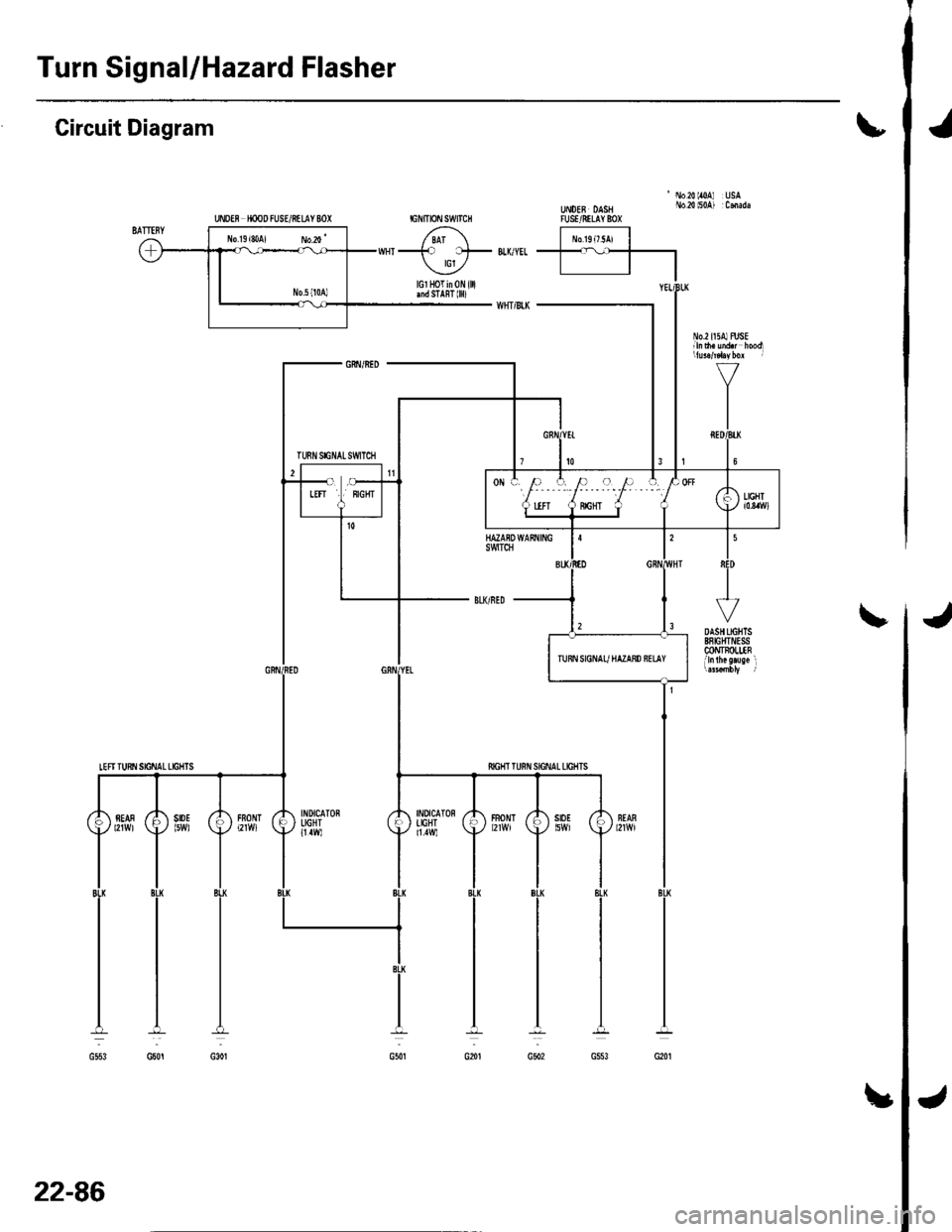
Circuit Diagram\
'No20lr0A USAUt oEB DASH No.2{ l50A) :CmadaTUSVRILAY 8OX
J
INDICATONIIGHT11.1W)
fiIGHT T
FBONT
22-86
!
Page 918 of 1139
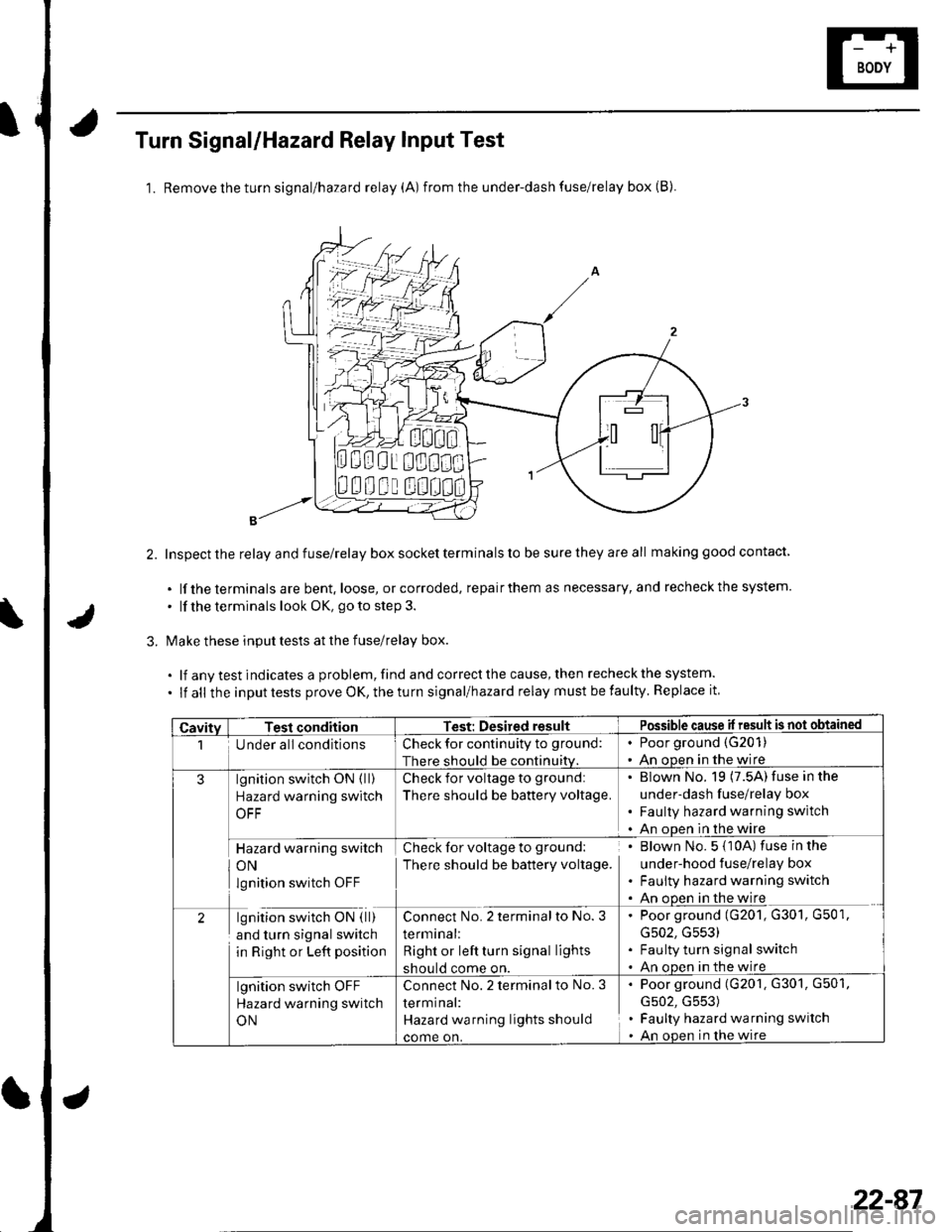
Turn Signal/Hazard Relay Input Test
1. Removetheturn signal/hazard relay (A) from the under-dash fuse/relay box (B).
Inspect the relay and fuse/relay box socket terminals to be sure they are all making good contact
. lf the terminals are bent. loose, or corroded, repairthem as necessary, and recheckthe system.
. lf the terminals look OK, go to step 3.
Make these input tests at the fuse/relay box.
.lfanvtestindicatesaproblem,findandcorrectthecause,thenrecheckthesystem.
. lf all the inputtests prove OK,theturn signal/hazard relay must befaulty. Replace it
000i 0!1000
00u! u0
CavitvTesl conditionTest: Desired resultPossible cause il result is not obtained
1Under all conditionsCheck for continuity to ground:
There should be continuiw.
. Poor ground (G201)
. An ooen in the wire
3lgnition switch ON ( ll)
Hazard warning switch
OFF
Check for voltage to ground:
There should be battery voltage.
' Blown No. 19 (7.5A) fuse in the
under-dash fuse/relay box. Faulty hazard warning switch. An ooen in the wire
Hazard warning switch
ON
lgnition switch OFF
Check for voltage to ground:
There should be battery voltage.
. Blown No. 5 {10A) fuse in the
under-hood fuse/relay box. Faulty hazard warning switch. An ooen in the wire
2lgnition switch ON ( ll)
and turn signal switch
in Right or Left position
Connect No. 2 terminalto No. 3
terminal:
Right or left turn signal lights
should come on.
. Poor ground (G201, G301, G501,
G502, G553). Faulty turn signal switch. An oDen in the wire
lgnition switch OFF
Hazard warning switch
ON
Connect No.2 terminal to No. 3
termrnal:
Hazard wa rning lights should
come on.
. Poor ground (G201, G301, G501,
G502, G553). Faulty hazard warning switch. An open in lhe wire
22-87
Page 919 of 1139
Turn Signal/Hazard Flasher
1.
2.
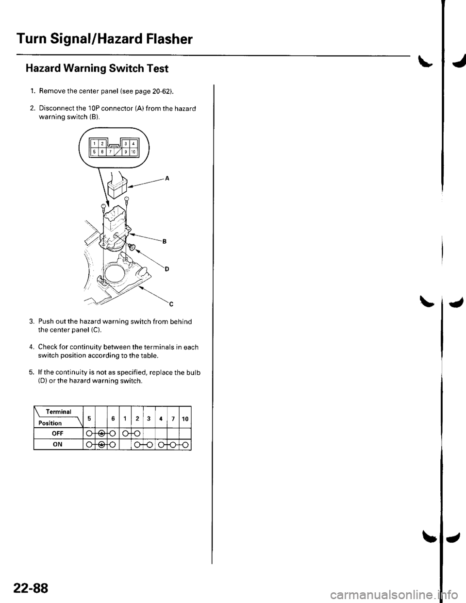
Hazard Warning Switch Test
Remove the center panel (see page 20-62).
Disconnect the 10P connector (A) from the hazard
warning switch (B).
4.
Push out the hazard warning switch from behind
the center panel (C).
Check for continuity between the terminals in each
switch position according to the table.
lf the continuity is not as specified, replace the bulb(D) orthe hazard warning switch.
Termin6l
;;;-_-\124710
OFF
ON@
3.
22-88
Page 920 of 1139
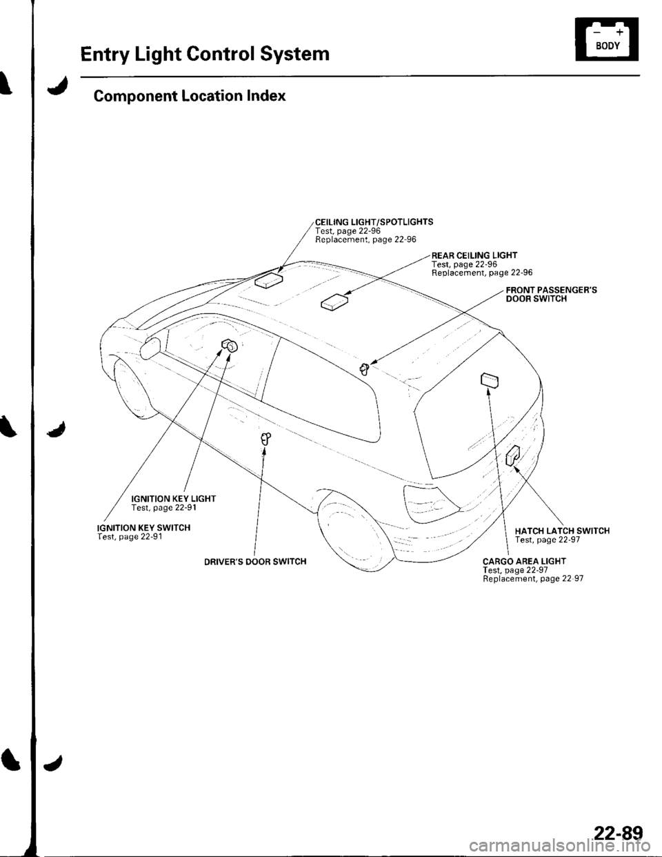
Entry Light Control System
Component Location Index
IGNITION KEY LIGHTTest, page 22-91
IGNITION KEY SWITCHlest, page 22-91
DRIVER'S DOOR SWITCH
CEILING LIGHT/SPOTLIGHTSTest, page 22-96Replacement, page 22-96
REAR CEILING LIGHTTest, page 22-96Replacement, page 22-96
FRONT PASSENGER'SDOOR SWITCH
HATCH LATCH SWITCHTest, page 22-97
CARGO AREA LIGHTTest, page 22-97Replacement, page 22 97
22-89
Trending: PGM-FI System, coolant, fog lights, windshield wipers, fuel filter location, fuel pump, alternator
