brake sensor HONDA CIVIC 2002 7.G Workshop Manual
[x] Cancel search | Manufacturer: HONDA, Model Year: 2002, Model line: CIVIC, Model: HONDA CIVIC 2002 7.GPages: 1139, PDF Size: 28.19 MB
Page 73 of 1139
Cruise Control
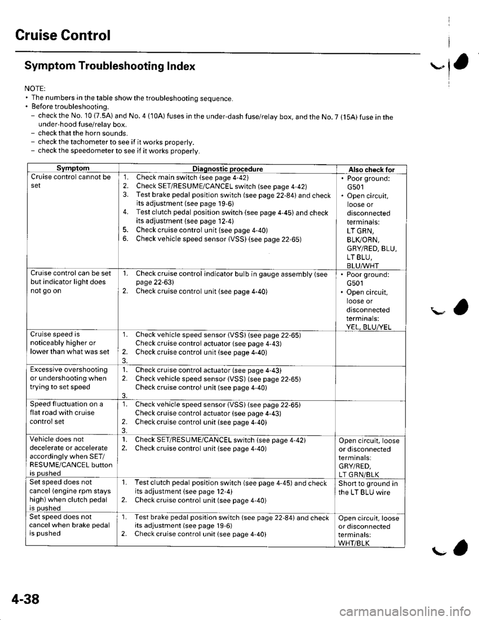
Symptom Troubleshooting Index
NOTE:' The numbers in the table showthetroubleshooting sequence.. Before troubleshooting.- check the No, 10 (7.5A) and No. 4 (10A) fuses in the under-dash fuse/relay box. and the No. 7 (15A) fuse in theunder-hood fuse/relay box,- check that the horn sounds.- check the tachometer to see if it works properly.- check the speedometer lo see if it works properly.
SymptomDiagnostic procedureAlso check forCruise control cannot be
set
1. Check main switch (see page 4-42)
2. Check SET/RESUME/CANCEL switch (see page 4-42)
3. Test brake pedal position switch (see page 22-84) and checkits adjustment {see page 19,6)
4. Test clutch pedal position switch (see page 4-45) and check
its adjustment (see page 12-41
5. Check cruise control unit {see page 4-40}
6. Check vehicle speed sensor (VSS) (see page 22-65)
. Poor ground:
G501. Open circuit,
loose or
disconnected
term inals:
LT GRN,
BLI(ORN.
GRY/RED, BLU.
LT BLU,
BLUAA/HTCruise control can be set
but indicator light does
not go on
1. Check cruise control indicator bulb in gauge assembly {seepage 22-631
2. Check cruise control unit (see page 4-40)
. Poor ground:
G501. Open circuit,
loose or
disconnected
termrnats:
YEL, BLUA/ELar, 'i.a c^aa.l ic
noticeably higher or
lower than what was set
1. Check vehicle speed sensor (VSS) {see page 22-65)
Check cruise control actuator {see page 4-43)
2. Check cruise control unit (see page 4-40)
Excessive overshooting
or undershooting when
trying to set speed
1. Check cruise control actuator (see page 4-43)
2. Check vehicle speed sensor (VSS) (see page 22-65)
Check cruise control unit (see page 4-40)
3.
Speed fluctuation on a
flat road with cruise
control set
1. Check vehicle speed sensor (VSS) (see page 22-65)
Check cruise control actuator (see page 4-43)
2. Check cruise control unit (see page 4-40)
Vehicle does not
decelerate or accelerate
accordingly when SET/
RESUME/CANCEL button
is pushed
1. Check SET/RESU ME/CANCEL switch (see page 4-42)2. Check cruise control unit {see page 4-40)
Open circuit, loose
or disconnected
terminals:
GRY/RED,
LT GRN/BLKSet speed does not
cancel (engine rpm stays
high) when clutch pedal
is pushed
1. Testclutch pedal position switch (see page 4-45) and checkits adjustment (see page 12-4)
2. Check cruise control unit (see page 4-40)
Short to ground in
the LT BLU wire
Set speed does not
cancel when brake pedal
is pushed
'1. Test brake pedal position switch (see page 22-84) and checkits adjustment (see page 19-6)
2. Check cruise control unit (see page 4-40)
Open circuit, loose
or disconnected
terminals:
WHT/BLK
4-38
g,
Page 118 of 1139
Gylinder Head Removal
NOTE:. Use fender covers to avoid damaging painted
surfaces.
To avoid damage, unplug the wiring connectors
carefully whlle holding the connector portion.
To avoid damaging the cylinder head, wait until the
engine coolant temperature drops below 100'F (38"C)
betore loosening the cylinder head bolts.
Mark all wiring and hoses to avoid misconnection.
Also, be sure that they do not contact other wiring or
hoses, or interfere with other parts.
'1.
2.
3.
Drain the engine coolant (see page 10-6).
Remove the drive belt (see page 4-26).
Remove the intake manifold {see page 9-3).
Remove the air cleaner housing (see step 7 on page
5-2t.
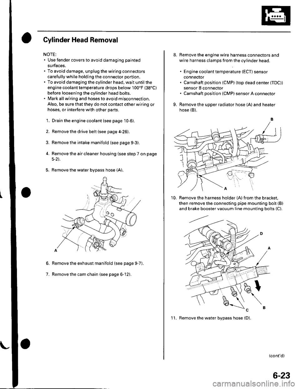
5. Remove the water bypass hose (A).
Remove the exhaust manifold (see page 9-7
Remove the cam chain (see page 6-12).
6.
7.
).
8. Remove the engine wire harness connectors and
wire harness clamps from the cylinder head.
. Engine coolant temperature (ECT) sensor
conneclor. Camshaft position (Cl\4P) (top dead center (TDC))
sensor B connector. Camshaft posilion (CMP) sensor A connector
9. Remove the upper radiator hose (A) and heater
hose (B).
'10. Remove the harness holder (A)from the bracket,
then remove the connecting pipe mounting boh {B)
and brake booster vacuum line mounting bolts {C).
(cont'd)
1 1. Remove the water bvpass hose (D).
6-23
Page 185 of 1139
Removal:
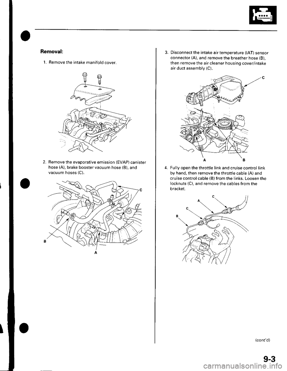
'1. Remove the intake manifold cover.
2.Remove the evaporative emission (EVAP) canister
hose (A), brake booster vacuum hose (B), and
vacuum hoses {C).
3. Disconnectthe intake airtemperature (lAT) sensor
connector (A), and remove the breather hose (B),
then remove the air cleaner housing cover/intake
air duct assembly (C).
4.Fully open the throttle link and cruise control link
by hand, then remove the throttle cable (A) and
cruise control cable (B) from the links. Loosen the
locknuts {C). and remove the cables from the
bracket.
(cont'd)
(
9-3
Page 188 of 1139
lntake Manifold and Exhaust System
Intake Manifold Removal and Installation (cont'd)
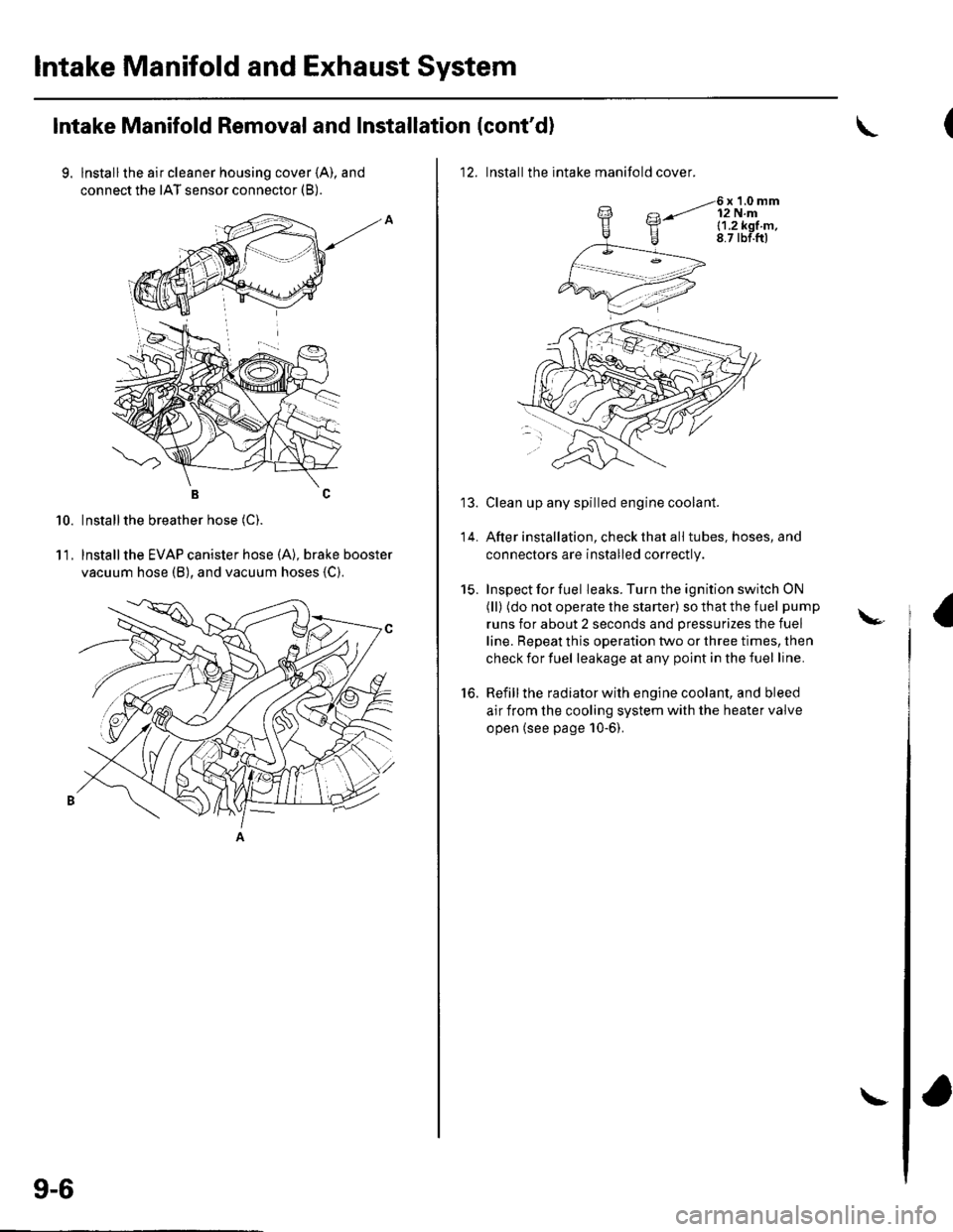
9. lnstallthe air cleaner housing cover (A), and
connect the IAT sensor connector (B).
BC
Installthe breather hose (C).
lnstallthe EVAP canister hose (A), brake booster
vacuum hose (B), and vacuum hoses {C).
10.
11.
9-6
\
12. Installthe intake manifold cover.
6x1.0mm12 N.ml.1.2k91.m,8.7 tbf.ftl
Clean up any spilled engine coolant.
After installation, check that all tubes, hoses, and
connectors are installed correctly.
Inspect for fuel leaks. Turn the ignition switch ON
(ll) (do not operate the starter) so that the fuel pump
runs for about 2 seconds and pressurizes the fuel
line. Repeat this operation two or three times, then
check for fuel leakage at any point in the fuel line.
Refill the radiator with engine coolant, and bleed
air from the cooling system with the heater valve
open (see page 10-6).
to.
\-
Page 208 of 1139
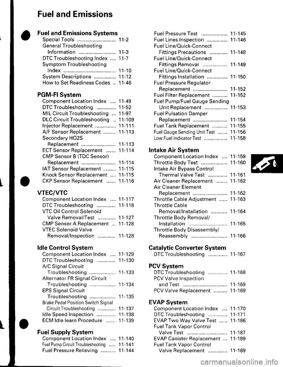
Fuel and Emissions
Fuel and Emissions Systems
SpecialTools
General Troubleshooting
Information
DTC Troubleshooting lndex ....
Symptom Troubleshooting
1ndex...............
System Descriptions ................
Howto Set Readiness Codes ..
PGM-FlSystem
Component Location Index ....
DTC Troubleshooting ..............
MIL Circuit Troubleshooting ...
DLC Circuit Troubleshooting ..
Injector Replacement ...............
A,/F Sensor Replacement .........
Secondary HO2S
Replacement
ECT Sensor Reolacement .......
CMP Sensor B {TDC Sensor)
Replacement
IAT Sensor Replacement .........
Knock Sensor Replacement ....
CKP Sensor Reolacement .......
VTEC/VTC
Comoonent Location Index ....
DTC Troubleshooting ..............
VTC Oil Control Solenoid
Valve Removal/Test .............
CMP Sensor A Replacement ...
VTEC Solenoid Valve
Removal/lnsoection .............
ldle Control System
Component Location Index
DTC Troubleshooting ..............
A,/C Signal Circuit
TroubleshootinS ...................
Alternator FR Signal Circu it
TroubleshootinS ...................
EPS Signal Circuit
TroubleshootinS ...................
Brake Pedal Position Switch Signal
Circuit Troubleshooting .............
ldle Speed Inspection
ECM ldle learn Procedure .......
Fuel Supply System
Component Location Index
Fuel Pump Circuit Troubleshooting
1't-2
I I-J
11-7
1 1-10
11-12
11-46
11-49
11-52
11-97
11-109
11-111
11-113
11-113
11-114
11-114
11-115
11-115
11-116
11-117
1 1-1 18
11-127
11-128
11-128
11-129
1I-130
I t- t55
11-134
1 1- 135
1 1-137
1 1-138
1 1-139
1 1-140
11-141
11-144
Fuel PressureTest ................... 11-145
Fuel Lines Inspection ............... 11-146
Fuel Line/Ouick-Connect
Fittings Precautions ............. 1 1-148
Fuel Line/Ou ick-Con nect
Fittings Removal .................. 1 1-149
Fuel Line/Ou ick-Con nect
Fittings lnstallation ............... 11-150
Fuel Pressure Regu lator
Replacement ......................... 11-152
Fuel Fifter Replacement ........... 11-152
Fuel Pump/Fuel Gauge Sending
UnitReDlacement ................. 11-153
Fuel Pulsation Damoer
Rep1acement ......................... 11-154
Fuel Tank Reolacement ........... 11-155
Fuel GaugeSending UnitTest ....... 11-156
Low Fuel lndicatorTest ................. 1 1-158
Intake Air System
Comoonent Location Index .... 11-159
Throttle BodyTest ................... 11-160
Intake Air Bypass Control
Thermal Valve Test .............. 11-161
Air Cleaner Reolacement ........ 11-162
Air Cleaner Element
Reolacement ......................... 11-162
Throttle Cable Adjustment ...... 11-163
Th rottle Cable
Removal/lnstallation ............ 1 1-164
Th rottle Body Removal/
Installation .. 11-165
Th rottle Body Disassembly/
Reassemblv .......................... 11-166
Catalytic Converter System
DTC Troubleshooting .............. 1 1-167
PCV System
DTC Troubleshooting .............. 1 1-168
PCV Valve InsDection
and Test ...... 1 1- 169
PCV Valve Reolacement .......... 11-169
EVAP System
Component Location Index .... 11-170
DTCTroubleshooting .............. 11-171
EVAP Two Way Valve Test ...... 11-186
Fuel Tank Vaoor Control
Valve Test ... 11-187
EVAP Canister Replacement ... 11-189
Fuel Tank Vaoor Control
Valve Reolacement .............. 1 1-189Fuel Pressu re Relieving ...........
Page 217 of 1139
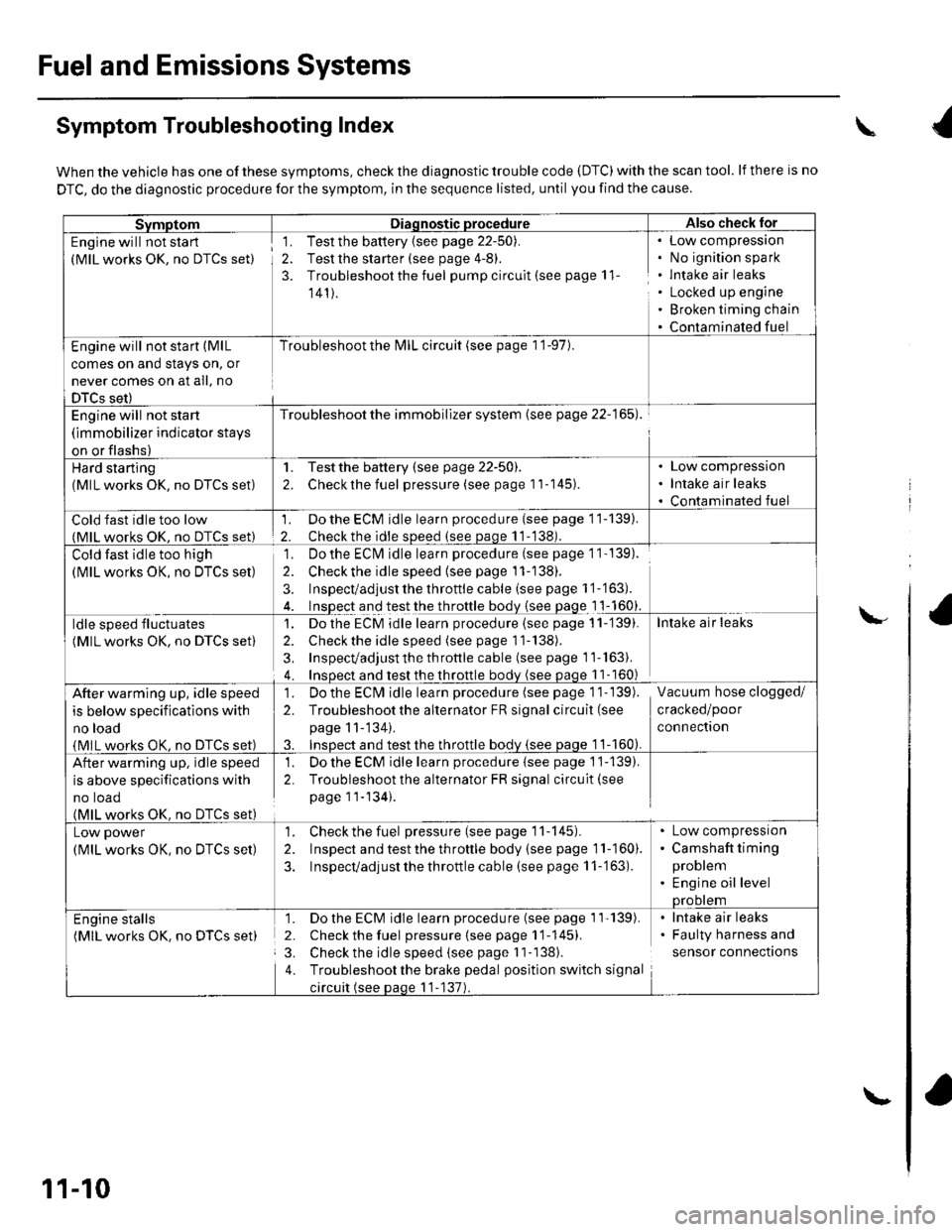
Fuel and Emissions Systems
Symptom Troubleshooting Index
When the vehicle has one of these symptoms, check the diagnostic trouble code (DTC) with the scan tool. lf there is no
DTC, do the diagnostic procedure for the symptom, in the sequence listed, until you find the cause.
SvmotomDiaqnostic procedureAlso check lor
Engine will not sta rt
(MlL works OK, no DTCS set)
1. Test the battery {see page 22-50).
2. Test the starter (see page 4-8).
3. Troubleshoot the fuel pump circult (see page 11
141).
Low compressron
No ignition spark
lntake air leaks
Locked up engine
Broken timing chain
Contaminated fuel
Engine will not start (MlL
comes on and stays on, or
never comes on at all, no
DTCS set)
Troubleshoot the l\4lL circuit (see page 1 '1-97).
Engine will not start
(immobilizer indicator stays
on or flashs)
Troubleshoot the immobilizer system (see page 22-165).
Hard starting(MlL works OK, no DTCS set)
1. Testthe battery (see page 22-50).
2. Checkthe fuel pressure (see page 11-145).
Low compression
Intake air leaks
Contaminated fuel
Cold fast idle too low(MlL works OK. no DTCS set)
1. Do the ECM idle learn procedure (see page 11-139).
2. Checkthe idle sDeed (see paqe 11-138).
Cold fast idle too high
(MlL works OK, no DTCS set)
Do the ECI\4 idle learn procedure (see page 1 1- 139).
Checkthe idle speed {see page 11-138).
Inspect/adjust the throttle cable (see page 1 '1-'163).
Inspect and test the throttle body {see page 1 1-160}.
']�
2.
3.
ldle speed fluctuates
(MlL works OK, no DTCS set)
1. Dothe ECM idle learn procedure (see page 11-'139).
2. Check the idle speed (see page 11-138).
3, Inspecvadjust th e throttle cable (see page 11''163).
4. Insoect and test the throttle bodv (see paqe 11- 160)
Intake air leaks
After warming up, idle speed
is below specifications with
no load
{MlL works OK, no DTCS set)
1. Do the ECIVI idle learn procedure (see page 1 1- 139).
2. Troubleshootthe alternator FR signal circuit (see
page 11-'134).
3. InsDect and test the throttle bodv {see paqe 1 1-160).
Vacuum hose clogged/
cracked/poor
connectron
After warming up, idle speed
is above specifications with
no toao(MlL works OK. no DTCS set)
1. Do the ECM idle learn procedure {see page 1'j-139).
2. Troubleshoot the alternator FR signal circuit(see
page 11-134).
Low power
(MlL works OK, no DTCS set)
1. Check the fuel pressure(seepagell-145).
2. Inspect and test the th roftle body (see page 11-160).
3. Inspecvadjust the throttle cable (see page 11-'163).
Low compressron
Camshaft timing
problem
Engine oil levelprootem
Engine stalls(MlL works OK. no DTCS set)
1. Do the ECM idle learn procedure (see page 1'l'139).
2. Check the fuel pressure{seepagell-145).
3. Check the idle speed (see page I 1-138).
4. Troubleshootthe brake pedal position switch signal
circuit (see paqe 11-137).
lntake air leaks
Faulty harness and
sensor connections
\
\-
11-10
\-
Page 239 of 1139
Fuel and Emissions Systems
(
{
System Descriptions (cont'd)
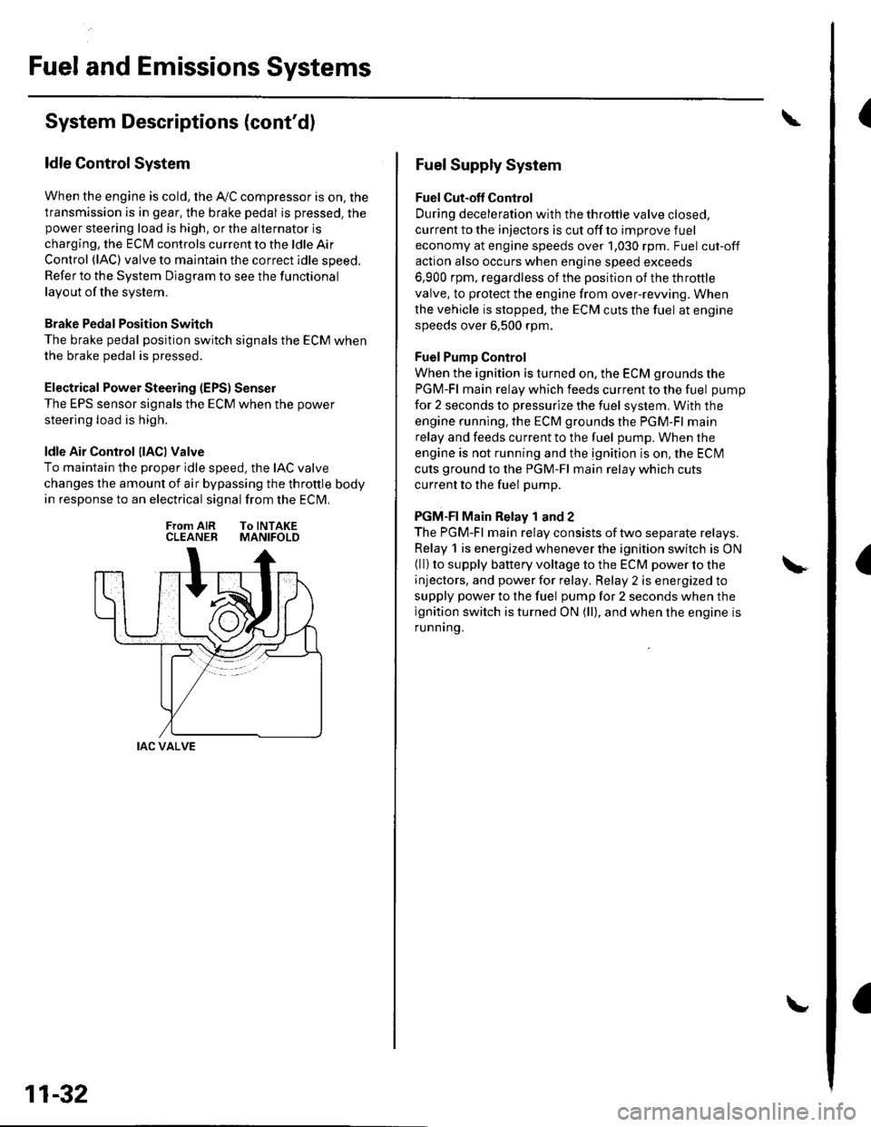
ldle Control System
When the engine is cold, the Ay'C compressor is on, the
transmission is in gear, the brake pedal is pressed. thepower steering load is high, or the alternator is
charging, the ECIM controls current to the ldle Air
Control (lAC) valve to maintain the correct idle speed.
Refer to the System Diagram to see the functional
layout of the system.
Brake Pedal Position Switch
The brake pedal position switch signals the ECM when
the brake pedal is oressed.
Electrical Power Steering (EPS) Senser
The EPS sensor signals the ECM when the power
steering load is high.
ldle Air Control llACl Valve
To maintain the proper idle speed, the IAC valve
changes the amount of air bypassing the throttle body
in response to an electrical signal from the ECM.
From AIR To INTAKECLEANER MANIFOLD
IAC VALVE
11-32
Fuel Supply System
Fuel Cut-off Control
During deceleration with the throttle valve closed,
current to the injectors is cut off to improve fuel
economy at engine speeds over 1,030 rpm. Fuel cut-off
action also occurs when engine speed exceeds
6,900 rpm, regardless of the position of the throttle
valve, to protect the engine from over-rewing. When
the vehicle is stopped. the ECM cuts the fuel at engine
speeds over 6,500 rpm.
Fuel Pump Control
When the ignition is turned on, the ECM grounds the
PGM-Fl main relay which feeds current to the fuel pump
for 2 seconds to pressurize the fuel system, With the
engine running. the ECM grounds the PGM-Fl main
relay and feeds current to the fuel pump. When the
engine is not running and the ignition is on, the ECI\4
cuts ground to the PGM-Fl main relay which cuts
current to the fuel pump.
PGM-FI Main Relay 1 and 2
The PGM-Fl main relay consists of two separate relays.
Relay 1 is energized whenever the ignition switch is ON(ll) to supply battery voltage to the ECM power to the
injectors, and power for relay, Relay 2 is energized to
supply power to the fuel pump for 2 seconds when the
ignition switch is turned ON (ll), and when the engine is
runnrng.
Page 579 of 1139
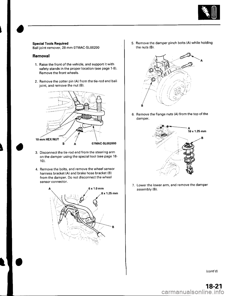
Special Tools Required
Ball joint remover,28 mm 07MAC-S100200
Removal
1. Raise the front of the vehicle, and support it with
safety stands in the proper location (see page 1-8).
Remove the front wheels.
Remove the cotter pin (A) from the tie-rod end ball
ioint, and remove the nut (B).
10 mm HEX NUT
07MAC-S1002000
Disconnectthe tie-rod end from the steering arm
on the damper using the specialtool (see page 18-
10 ).
Remove the bolts, and remove the wheel sensor
harness bracket {A) and brake hose bracket (B)
from the damper. Do not disconnect the wheel
4.
sensor connector.
A6x1.0mm
/.8
x 1.25 nm
q
5. Remove the damper pinch bolts (A)while holding
the nuts (B).
6. Remove the flange nuts (A)from the top ofthe
damper,
A10 x 'l.25 mm
7. Lower the lower arm, and remove the damper
assembly (B).
(cont'd)
18-21
Page 583 of 1139
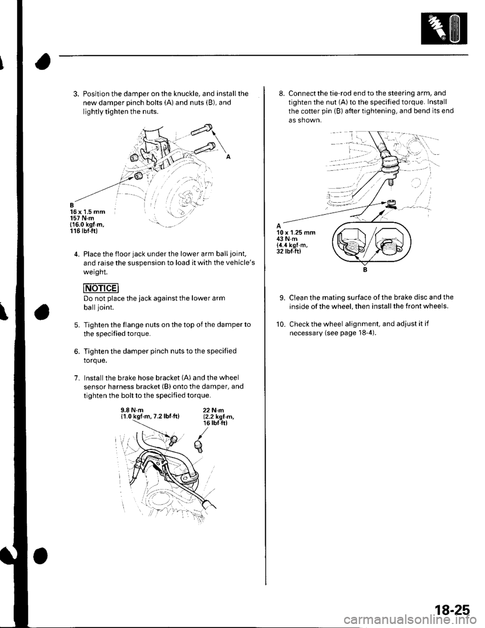
3. Position the damper on the knuckle, and installthe
new damper pinch bolts (A) and nuts (B), and
lightly tighten the nuts.
B16x 1,5 mm157 N.m(16.0 kgt m,116 tbt.ftl
4. Place the floor jack under the lower arm balljoint,
and raise the suspension to load it with the vehicle's
weight.
Do not place the jack against the lower arm
balljoint.
Tighten the flange nuts on the top of the damper to
the specified torque.
Tighten the damper pinch nuts to the specified
torque.
Install the brake hose bracket (A) and the wheel
sensor harness bracket (B) onto the damper, and
tighten the bolt to the specified torque.
5.
1.
9.8 N.m11.0 kgf.m, 7.2lbf.ftl22N|rl.12.2 kgI m,16 rbr,ftl
q
8. Connect the tie-rod end to the steering arm, and
tighten the nut (A) to the specified torque. Install
the cotter pin (B) after tightening, and bend lts end
as shown.
9. Clean the mating surface ofthe brake disc and the
inside of the wheel, then install the front wheels.
10. Check the wheel alignment, and adjustitif
necessary {see page 18-4).
18-25
Page 586 of 1139
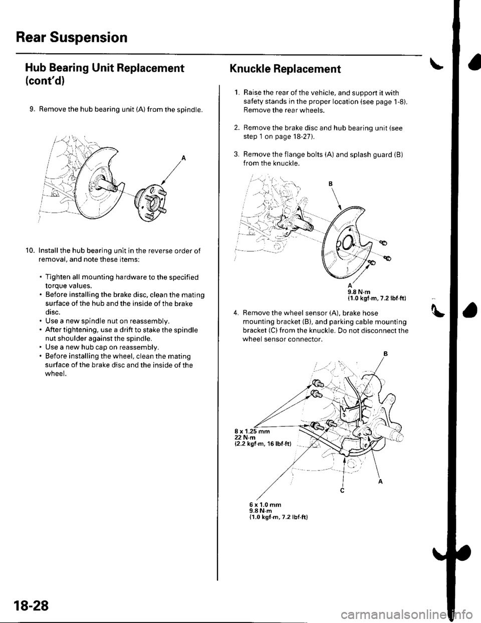
Rear Suspension
Hub Bearing Unit Replacement
(cont'd)
9. Remove the hub bearing unit (A) from the spindle.
Install the hub bearing unit in the reverse order of
removal, and note these items:
. Tighten all mounting hardware to the specified
torque values,. Before installing the brake disc, clean the mating
surface ot the hub and the inside of the brake
disc.. Use a new spindle nut on reassembly.. After tightening, use a drift to stake the spindle
nut shoulder against the spindle.. Use a new hub cap on reassembly.. Before installing the wheel, clean the mating
surface of the brake disc and the inside of the
wneel.
10.
,=,,,
18-28
Raise the rear of the vehicle, and suppon it with
safety stands in the proper location (see page 1-8).
Remove the rear wheels.
Remove the brake disc and hub bearing unit (see
step 1 on page 18-27).
Remove the flange bolts (A) and splash guard (B)
from the knuckle.
11.0 kgf.m, 7.2 lbf ft)
4. Remove the wheel sensor(A), braKe nose
mounting bracket (B), and parking cable mounting
bracket (C) from the knuckle. Do not disconnect the
wheel sensor connector.
8 x 1.25 mm22 N.m{2.2 kgf m, 16 lbf ftl
Knuckle Replacement
1.
6x1.0mm9.8 N,m{I.0 kgt.m,7.2 lbf ft)
tt