Control HONDA CIVIC 2003 7.G Owners Manual
[x] Cancel search | Manufacturer: HONDA, Model Year: 2003, Model line: CIVIC, Model: HONDA CIVIC 2003 7.GPages: 1139, PDF Size: 28.19 MB
Page 377 of 1139
EVAP System
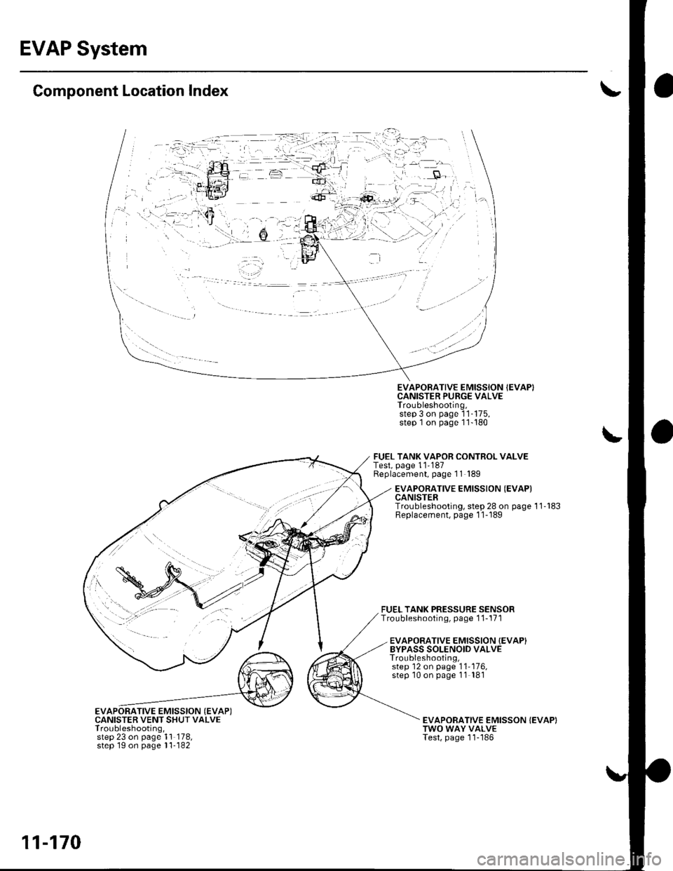
Component Location Index
EVAPORATIVE EMISSION {EVAP)CANISTER VENT SHUT VALVETroubleshooting,step 23 on page 1'l 178,step 1g on page l1- 182
EVAPORATIVE EMISSION IEVAPICANISTER PURGE VALVETroubleshooting,step 3 on page 'l1-175,
step 1on page 11-180
FUEL TANK VAPOR CONTROL VALVETest, page 11'187Replacement, page 11 189
FUEL TANK PRESSURE SENSORTroubleshooting, page 1 1-171
EVAPORATIVE EMISSION {EVAPICANISTERTroubleshooting, step 28 on page 11'183Replacement, page 1 1-189
EVAPORATIVE EMISSION {EVAP}BYPASS SOLENOID VALVETroubleshooting,step 12 on page '11'176,
step '10 on page 11 181
EVAPOBATIVE EMISSON {EVAP)TWO WAY VALVETest, page 'l1-'186
11-170
Page 382 of 1139
DTC Pl456: EVAP Control(Fuel Tank Svstem)
System Leakage
The fuel system is designed to allow specified
maximum vacuum and pressure conditions. Do not
deviate from the vacuum and pressure tests as
indicated in these procedures. Excessive pressure/
vacuum would damage the EVAP components or cause
eventual fuel tank failure.
Special Tools Required
Vacuum Pump/Gauge, 0-30 in. Hg A973X-041-XXXXX
This is a two-trip code. Once cleared, it cannot be
reproduced in one trip. Also, cenain specific driving
and ambient conditions must occur before the ECM will
complete the system checks. Additional test drives may
still not meet the specific conditions needed to
reproduce the code.
Follow these troubleshooting procedures carefully to
ensure the integrity of the system and to confirm the
cause of the problem or code.
NOTE: Fresh fuel has a higher volatility that createsgreater pressure/vacuum. The optimum condltlon for
testing is fresh fuel, and must be less than a full tank. lf
possible, to assist in leak detection, add 1 gallon of
fresh fuel to the tank (as long as it will not fill the tank).just before starting these procedures.
Fuel Fill Cap Check
1. Check the fuel fill cap (the cap must say "lf not
tightened 3 clicks check engine light may come
on" ).
ls the proper luel till cap installed and properly
tightened?
YES Go to step 2.
NO- Replace or tighten the cap.I
2. Check the fuel fill cap seal.
ls the tuel fill cap seal missing or damaged?
YES- Replace the fuel fill cap.I
NO The fuelfill cap is OK. Go to step 3.
EVAP Canister Purge Valve Test
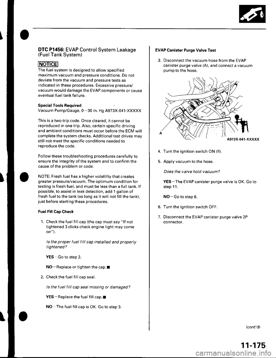
3. Disconnect the vacuum hose from the EVAP
canister purge valve (A), and connect a vacuum
oumo to the hose.
A973X-041-XXXXX
Turn the ignition switch ON (ll).
Apply vacuum to the hose.
Does the valve hold vacuum?
YES-The EVAP canister purge valve is OK. Go to
step 11.
NO-Go to step 6.
Turn the ignition switch OFF.
Disconnect the EVAP canister purge valve 2P
connecror.
5.
7.
{cont'd)
11-175
Page 386 of 1139
28.
29.
ls thete continuity?
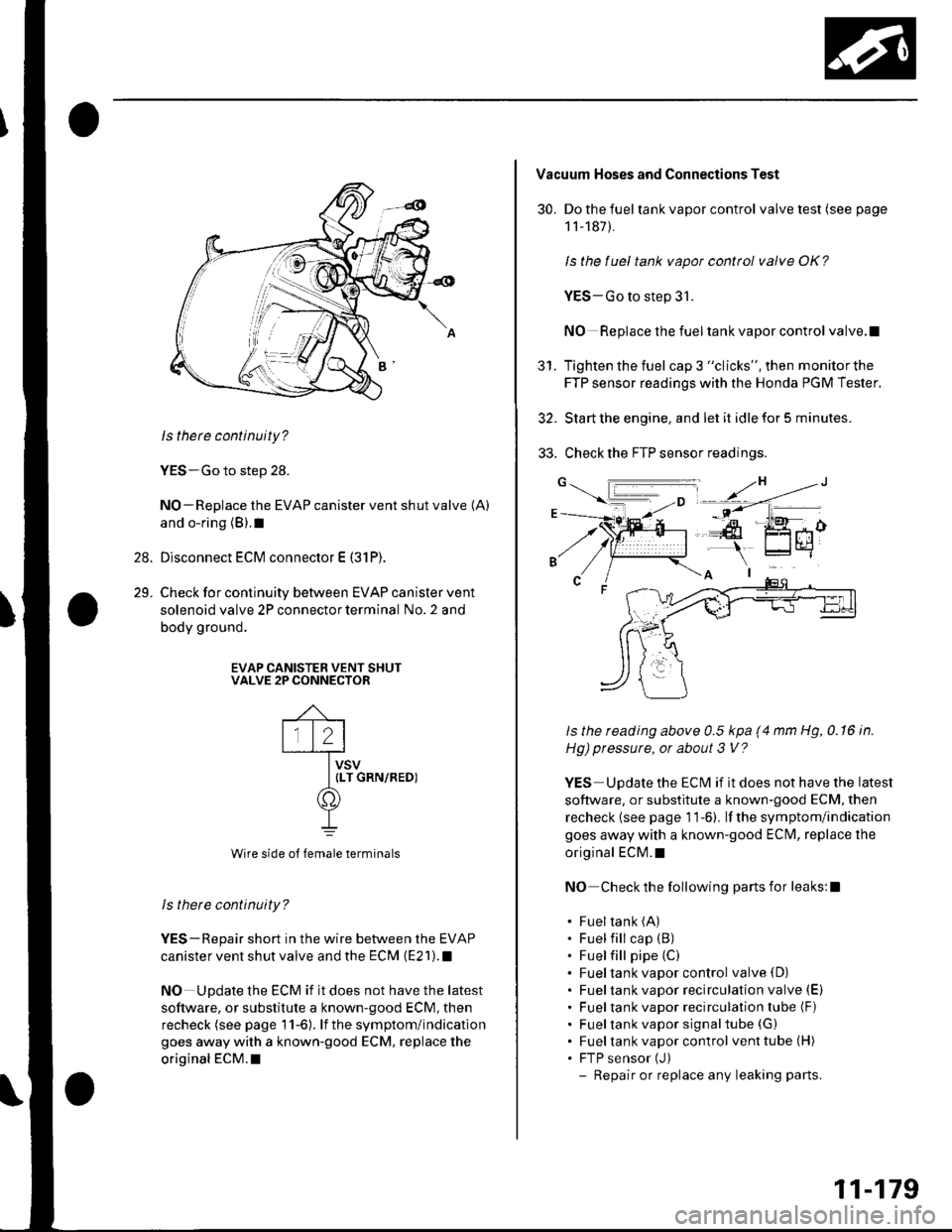
YES-Go to step 28.
NO-Replace the EVAP canister vent shut valve (A)
and o-ring (B).1
Disconnect ECM connector E (31P).
Check for continuity between EVAP canister vent
solenoid valve 2P connector terminal No. 2 and
body ground.
EVAP CANISTER VENT SHUTVALVE 2P CONNECTOR
Wire side o{ female terminals
ls there continuity?
YES-Repair short in the wire between the EVAP
canister vent shut valve and the ECM (E21).1
NO Update the ECM if it does not have the latest
soflware, or substitute a known-good ECM, then
recheck (see page 11-6). lf the symptom/indication
goes away with a known-good ECM, replace the
original ECM.I
30.
Vacuum Hoses and Connections Test
Do the fuel tank vapor control valve test (see page
1 1-187).
ls the fuel tank vapot control valve OK?
YES-Go to step 31.
NO Replace the fueltank vapor control valve.l
Tighten the fuel cap 3 "clicks", then monitorthe
FTP sensor readings with the Honda PGM Tester.
Start the engine. and let it idle for 5 minutes.
Check the FTP sensor readings.
ls the reading above 0.5 kpa (4 mm Hg, 0.16 in.
Hg) pressure, or about 3 V?
YES Update the ECM if it does not have the latest
software, or substitute a known-good ECM, then
recheck {see page 1 1-6). lf the symptom/indication
goes away with a known-good ECfvl, replace the
original ECM.t
NO Check the following parts for leaks:l
. Fueltank (A)
. Fuel fill cap (B)
. Fuel fill pipe (C)
. Fueltank vapor control valve(D). Fueltank vapor recirculation valve (E)
. Fueltank vapor recirculation tube (F)
. Fueltank vapor signaltube (G)
. Fueltank vapor control venttube(H). FTP sensor (J)
- Repair or replace any leaking parts.
5t.
11-179
Page 387 of 1139
EVAP System
DTC Troubleshooting (cont'd)
DTC Pl457: EVAP Control System(EVAP Canister System)
Leakage
The fuel system is designed to allow specified
maximum vacuum and pressure conditions. Do not
deviate from the vacuum and pressure tests as
indicated in these procedures. Excessive pressure/
vacuum would damage the EVAP components or
cause eventual fuel tank system failure.
SpecialTools Required
Vacuum pump/gauge, 0-30 in.Hg A973X-041-XXXXX
This is a two-trip code. Once cleared, it cannot be
reproduced in one trip. Also, certain specific driving
and ambient conditions must occur before the ECfM will
complete the system checks, Additional test drives may
still not meet the specific conditions needed to16^r^.1' '^6 rh6 ^^.16
Follow these troubleshooting procedures carefully to
ensure the integrity of the system and to confirm the
cause of the problem or code.
NOTE: Fresh fuel has a higher volatility lhat creates
greater pressure/vacuum. The optimum condition for
testing is fresh fuel, and there must be less than a full
tank. lf possible, to assist in leak detection, add I gallon
of fresh fuel to the tank (as long as it will not fill the
tank), just before starting these procedures.
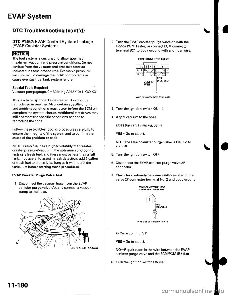
EVAP Canister Purge Valve Test
1. Disconnect the vacuum hose from the EVAP
canister purge valve (A), and connect a vacuumpump to the hose.
11-180
4973X-041-XXXXX
ECM CONNECTOR A I24P'
Wire side of lemale terminals
4.
7.
2. Turn the EVAP canister purge valve on with the
Honda PGM Tester, or connect ECM connector
terminal 821 to body ground with a jumper wire.
Turn the ignition switch ON (ll).
Apply vacuum to the hose.
Does the valve hold vacuum?
YES-Go to step 5.
NO-The EVAP canister purge valve is OK. Go to
step 10.
Turn the ignition switch OFF.
Disconnect the EVAP canister purge valve 2P
conneclor,
Check for continuity between EVAP canister purge
valve 2P connector terminal No. 2 and body ground.
EVAPCANISTEN PURG€VALVE 2P CONNECTOR
-4-
lll2l-fircs
IYEL/8Lu)(f])
I
Wire side offemale lerminals
ls there continuity?
YES-Go to step 8.
NO Repair open in the wire between the EVAP
canister purge valve and the ECM/PCM (821).I
Turn the ignition switch ON (ll).
t
b.
8.
Page 391 of 1139
EVAP System
DTC Troubleshooting (cont'dl
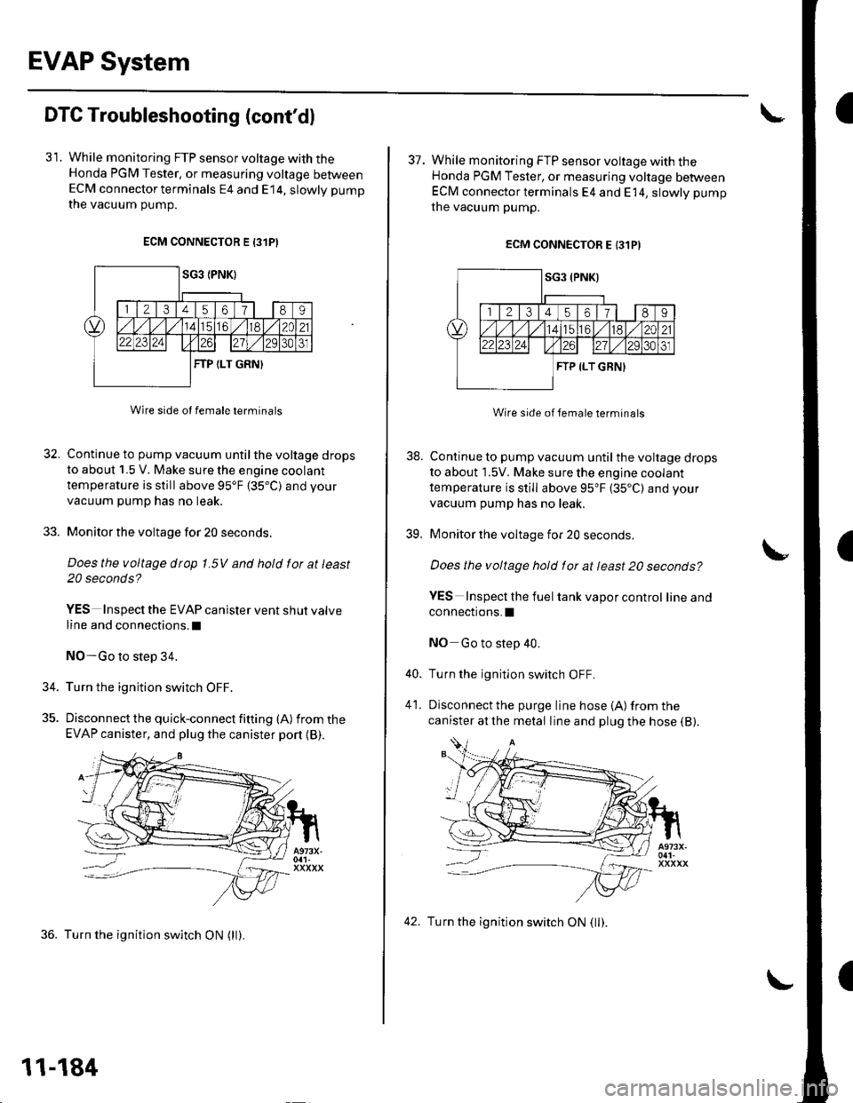
31. While monitoring FTP sensor voltage with theHonda PGM Tester, or measuring voltage betweenECM connector terminals E4 and E14, slowly pump
the vacuum oumD.
ECM CONNECTOR E 13lPI
Wire side ot female terminals
32. Continue to pump vacuum until the voltage drops
to about 1.5 V. Make sure the engine coolant
temperature is still above 95'F 135.C) and your
vacuum pump has no leak.
33. Monitor the voltage for 20 seconds.
Does the voltage drop 1.5V and hold for at least
20 seconds?
YES Inspect the EVAP canister vent shut valve
line and connections.l
NO-Go to step 34.
34. Turn the ignition switch OFF.
35. Discon nect the quick-con nect fitting (A) fromthe
EVAP canister, and plug the canister port {B).
36. Turn the ignition switch ON (ll).
11-184
42. Turn the ignition switch ON (ll).
I
38.
39.
37. While monitoring FTP sensor voltage with theHonda PGM Tester, or measuring voltage betweenECM connector terminals E4 and E 14, slowly pump
the vacuum pump.
ECM CONNECTOR E {31PI
Wire side of lemale terminals
Continue to pump vacuum until the voltage drops
to about 1.5V. Make sure the engine coolant
temperature is still above 95"F (35"C) and your
vacuum pump has no leak.
Monitor the voltage for 20 seconds
Does the voltage hold for at least 20 seconds?
YES Inspecl the fuel tank vapor control lineand
connections.I
NO Go to step 40.
Turn the ignition switch OFF.
Disconnect the purge line hose {A) from the
canister at the metal line and plug the hose (B).
40.
41.
Page 392 of 1139
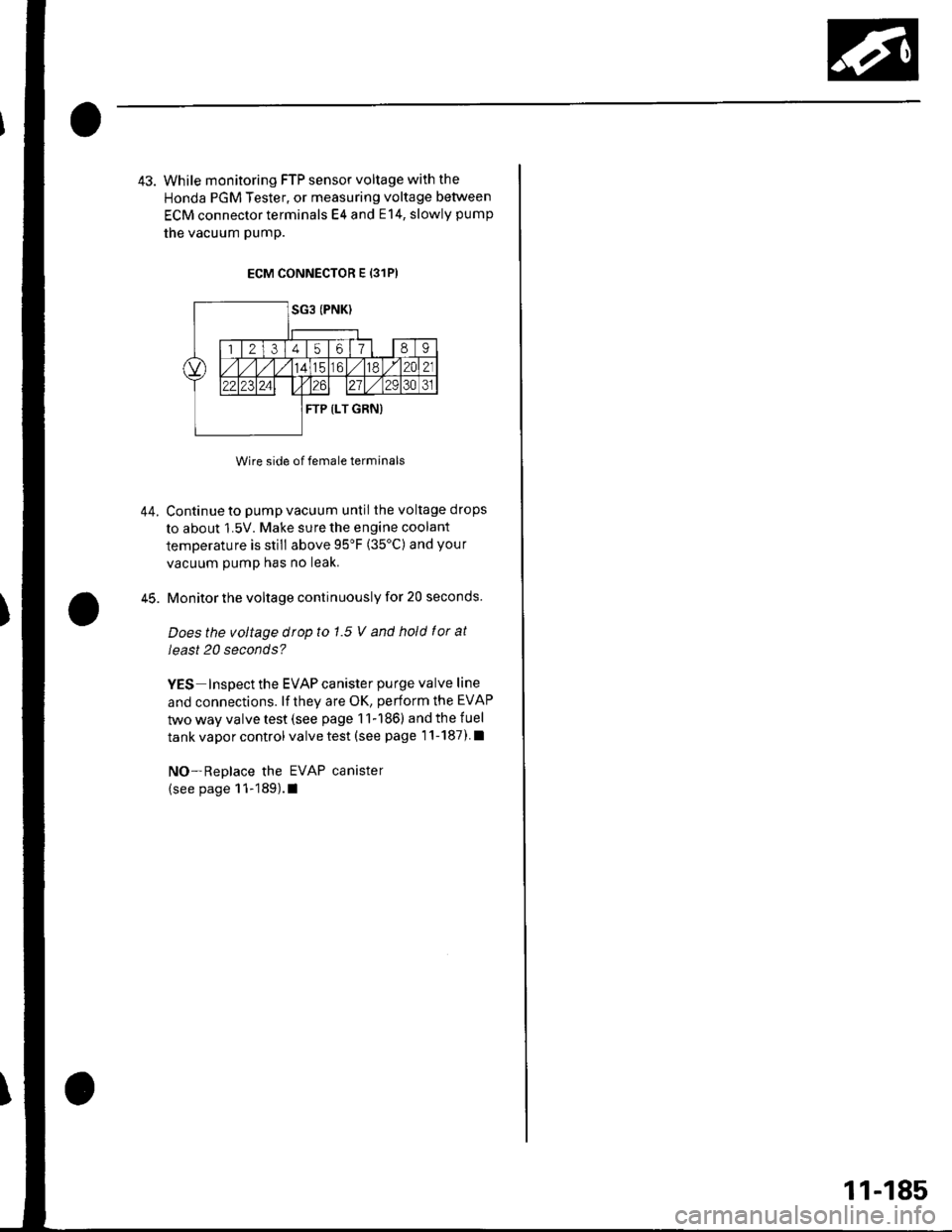
43. While monitoring FTP sensor voltage with the
Honda PGM Tester, or measuring voltage between
ECM connector terminals E4 and E14, slowly pump
the vacuum pump.
ECM CONNECTOR E {31P)
Wire side of female terminals
Continue to pump vacuum until the voltage drops
to about 1.5V. Make sure the engine coolant
temperature is still above 95'F (35'C) and your
vacuum pump has no leak.
Monitor the voltage continuously for 20 seconds.
Does the voltage drop to 1.5 V and hold f or at
least 20 seconds?
YES Inspect the EVAP canister purge valve line
and connections. lf they are OK, perform the EVAP
two way valve test (see page 11-186) and the fuel
tank vapor control valve test (see page 1'l-187) l
NO-Replace the EVAP canister
(see page 11-189).1
44.
45.
11-185
Page 394 of 1139
FuelTank Vapor Control Valve Test
Special Tools Required
Vacuum Pump/Gauge, 0-30 in. Hg A973X-041-XXXXX
Float Test
1. Make sure the fuel tank is less than half full.
2. Remove the fuel fill cap to relieve fuel tank
pressure, then reinstall the cap.
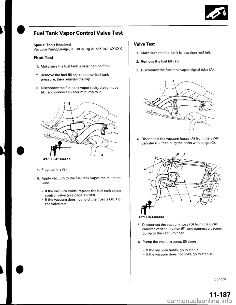
3. Disconnect the fuel tank vapor recirculation tube
{A), and connect a vacuum PumP to it.
Plug the line (B).
Apply vacuum to the fuel tank vapor recirculation
tuDe.
lf the vacuum holds, replace the fuel tank vapor
control valve (see page 11-189).
lf the vacuum does not hold, the float is OK. Do
the valve test.
5.
A973X-041-XXXXX
Valve Test
1. N4ake sure the fuel tank is less than half full
2. Remove the fuel fill cap.
3. Disconnect the fuel tank vapor signal tube (A).
Disconnect the vacuum hoses (A) from the EVAP
canister (B), then plug the ports with plugs (C)4.
A973X-O41-XXXXX
5. Disconnect the vacuum hose (D) from the EVAP
canister vent shut valve (E), and connect a vacuum
pump to the vacuum hose.
6. Pump the vacuum pump 80 times.
. lf the vacuum holds, goto steP 7.. lf the vacuum does no1 hold, go to step 10.
(cont'd)
11-187
Page 395 of 1139
EVAP System
FuelTank Vapor ControlValve Test (cont'd)
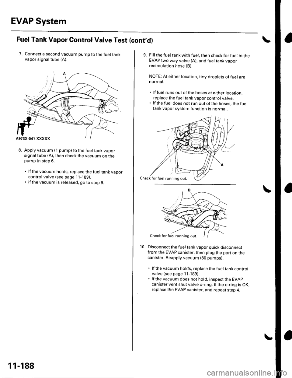
7. Connect a second vacuum pump to the fuel tankvapor signaltube (A).
8. Apply vacuum (1 pump) to the fuel tank vaporsignal tube (A). then check the vacuum on thepump in step 6.
. lf the vacuum holds, replace the fueltank vapor
control valve {see page 11-189).. If the vacuum is released, goto step 9.
11-188
10.
Fill the fuel tank with fuel, then check for fuel in theEVAP two way valve (A), and fuel tank vaporrecirculation hose (B).
NOTE: At either location, tiny droplets of fuel arenormal.
. lf fuel runs out of th e hoses at either location,
replace the fuel tank vapor control valve..lfthefuel does not run out of the hoses, the fuel
tank vapor system function is normal.
Disconnect the fuel tank vapor quick disconnectfrom the EVAP canister, then plug lhe port on the
canister. Reapply vacuum (80 pumps).
. lf the vacuum holds, replace the fuel tank control
valve (see page 1 1-189).. lf the vacuum does not hold, insDect the EVAP
canister vent shut valve o-ring. lf the o-ring is OK,replace the EVAP canister, and repeat step 4.
Check for fuel rirnning out.
Check for fuel running out.
Page 396 of 1139
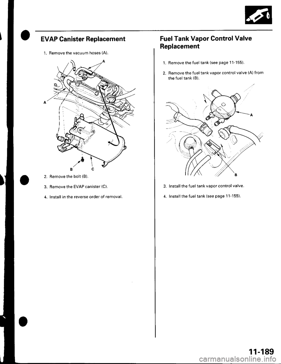
EVAP Canister Replacement
l. Remove the vacuum hoses (A).
2. Remove the boit (B).
3. Remove the EVAP canister (C).
4. Install in the reverse order of removal.
Fuel Tank Vapor Control Valve
Replacement
1. Remove the fuel tank(seepagell-155).
2. Remove the fueltank vapor control valve(A) from
the fuel tank (B).
Install the fuel tank vapor control valve.
Install the fuel tank (see page 1 'l -155).
3.
4,
11-189
Page 423 of 1139
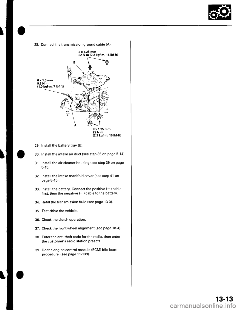
28. Connect the transmission ground cable (A).
8 x 1.25 mm
B
22 N.m (2.2 kgf.m, 16lbf.ft)
[---.-.---e
e
6x1,0mm9.8 N.m{1.0 kgl m. 7 lbf ftl
29.
30.
8x125mm22Nm12.2 kgt m, 16 lbf ft)
lnstall the battery tray (B).
Installthe intake air duct (see step 36 on page 5-14).
Installthe air cleaner housing (see step 39 on page
5-15).
Installthe intake manifold cover (see step 41 on
page 5-15).
Install the battery. Connectthe positive (+) cable
first, then the negative (-)cable to the battery.
Reflllthe transmission fluid (see page 13-3).
Test-drive the vehicle.
Check the clutch operation.
Check the front wheel alignment (see page 18-4).
Enter the anti-theft code for the radio, then enter
the customer's radio station presets.
Do the engine control module (ECM) idle learn
procedure (see page 11-139).
32.
33.
34.
35.
36.
31.
38.
39.
13-13