Control HONDA CIVIC 2003 7.G Workshop Manual
[x] Cancel search | Manufacturer: HONDA, Model Year: 2003, Model line: CIVIC, Model: HONDA CIVIC 2003 7.GPages: 1139, PDF Size: 28.19 MB
Page 498 of 1139
Steering
Steering Wheel Removal
SRS components are located in this area. Review the
SRS component locations (see page 23-13), and
precautions and procedures (see page 23-14) in the SRS
section before performing repairs or service.
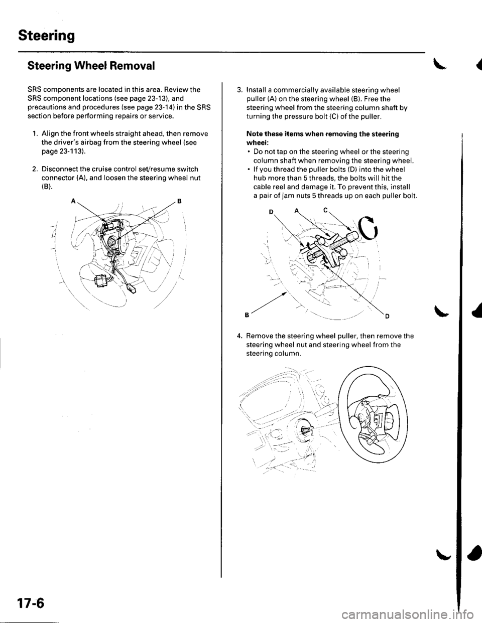
1. Align the front wheels straight ahead, then remove
the driver's airbag from the steering wheel (see
page 23-113).
2. Disconnect the cruise control sevresume switch
connector (A), and loosen the steering wheel nut
{B).
i
17-6
3. Install a commercially available steering wheel
puller {A) on the steering wheel (B). Free the
steering wheel from the steering column shaft by
turning the pressure bolt (C) ofthe puller.
Note these items when removing the steering
wheel:. Do not tap on the steering wheel orthesteering
column shaft when removing the steering wheel.. lf you thread the puller bolts (D) intothewheel
hub more than 5 threads, the bolts will hit the
cable reel and damage it. To prevent this, install
a pair of jam nuts 5 threads up on each puller bolt.
D
Bemove the steering wheel puller, then remove the
steering wheel nut and steering wheel from the
sleerino column.
{
Page 499 of 1139
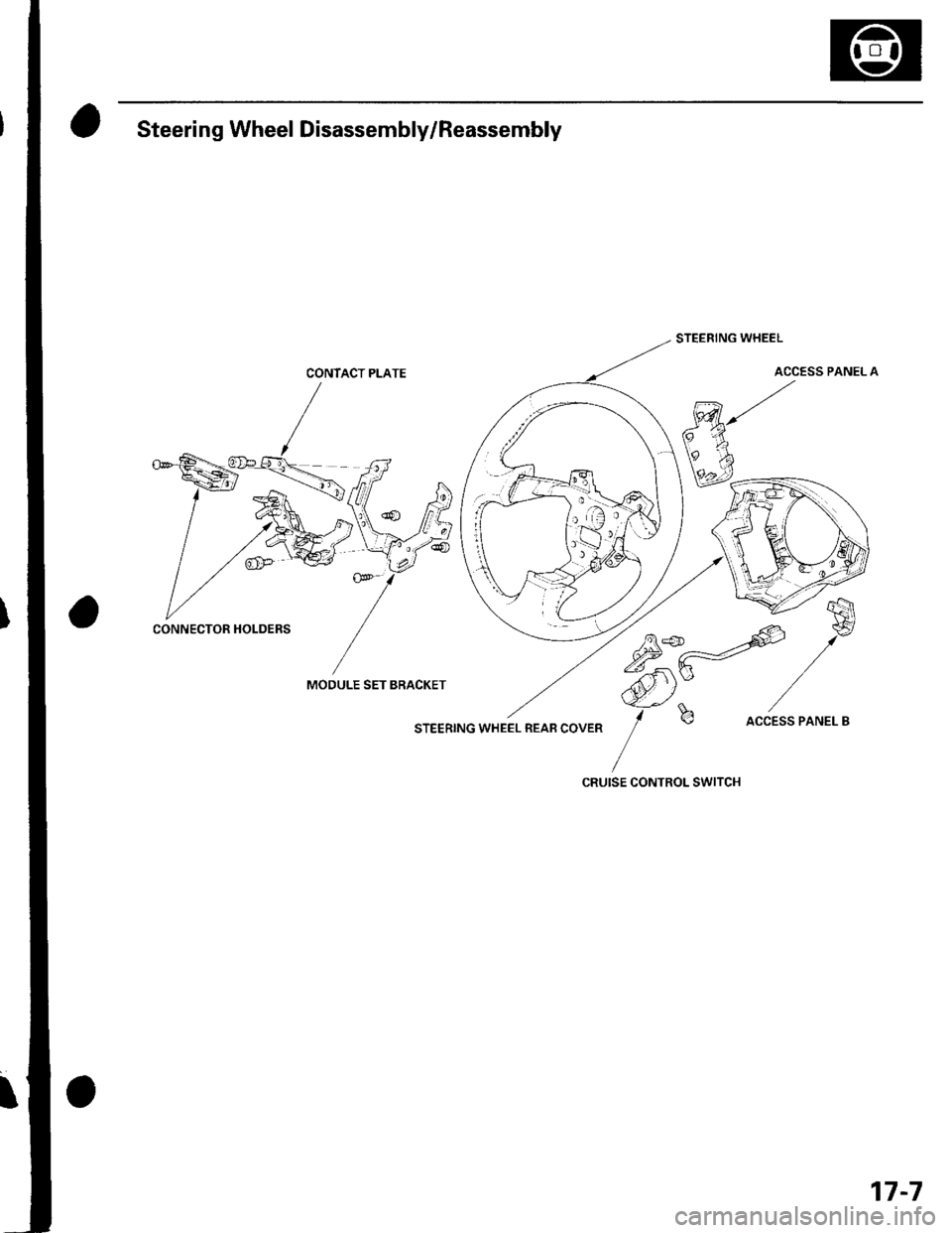
Steering Wheel Disassembly/Reassembly
CONTACT PLATE
MOOULE SET BRACKET
STEERING WHEEL REAB COVER
STEERING WHEEL
ACCESS PANEL A
75*-=offi
,/*
ffi)Y /-f
b accEss PANEL B
CRUISE CONTROL SWITCH
CONNECTOR HOLDERS
17-7
Page 500 of 1139
Steering
Steering Wheel Installation
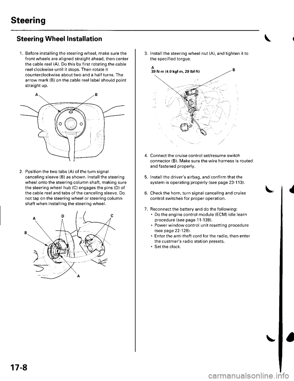
1. Before installing the steering wheel, make sure the
front wheels are aligned straight ahead, then center
the cable reel (A). Do this by first rotating the cable
reel clockwise until it stops. Then rotate it
counterclockwise about two and a half turns. The
arrow mark (B) on the cable reel label should point
straight up.
Position the two tabs (A) of the turn signal
canceling sleeve (B) as shown. Installthe steering
wheel onto the steering column shaft, making sure
the steerlng wheel hub (C) engages the pins (D) of
the cable reel and tabs of the canceling sleeve. Do
not tap on the steering wheel or steering column
shaft when installing the steering wheel.
17-8
3. Install the steering wheel nut (A), and tighten it to
the specified torgue.
A_B39 N.m (4.0 kgf m.29lbt ftl
Connect the cruise control set/resume switch
connector (B). fvlake sure the wire harness is routed
and fastened properly.
Install the driver's airbag, and confirm that the
system is operating properly {see page 23-113).
Check the horn, turn signal canceling and cruise
control switches for proper operation.
Reconnect the battery and do the following:. Do the engine control module (ECM) idle learn
procedure (see page 1l-139),. Power window control unit resetting procedure
\see page 22-1281.. Enter the anti-theft cord for the radio, then enter
the custmer's radio station presets.. Set the clock.
{
7.
lr,',,t
;. _,:!
'' '1i::..'.' l
Page 502 of 1139
Steering
Steering Column Removal
lnstallation
1.
4.
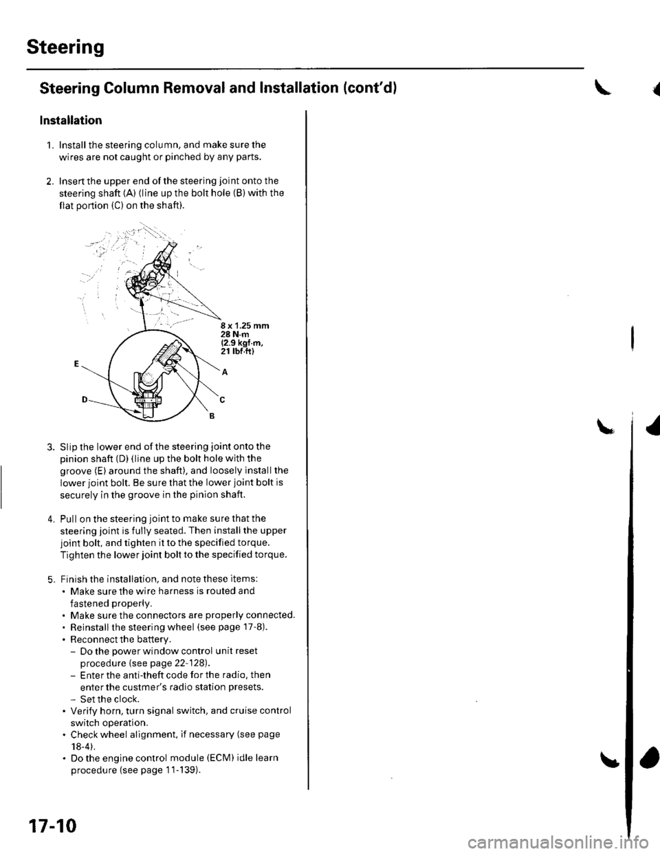
Install the steering column, and make sure the
wires are not caught or pinched by any parts.
Insertthe upper end ofthe steering joint onto the
steering shaft {A) (line up the bolt hole (B) with the
flat portion (C) on the shaft).
8 x 1,25 mm28 N.m{2.9 kgf m,21 rbr.ft)
A
Slip the lower end of the steering joint onto the
pinion shaft {D) (line up the bolt hole with the
groove (E) around the shaft), and loosely lnstallthe
lower joint bolt. Be sure that the lower joint bolt is
securely in the groove in the pinion shaft.
Pull on the steering joint to make su re that the
steering joint is fully seated. Then installthe upper
joint bolt, and tighten it to the specified torque.
Tighten the lower joint bolt to the specified torque.
Finish the installation, and note these items:
. Make sure the wire harness is routed and
fastened properly.
. Make sure the connectors are properly connected.. Reinstallthe steering wheel (see page 17-8).
. Reconnect the battery.- Do the power window control unitreset
procedure {see page 22-128).- Enter the anti-theft code for the radio, then
enter the custmer's radio station presets.
- Set the clock.. Verify horn, turn signal switch, and cruise control
switch operation.. Check wheel alignment, if necessary (see page
18-4).. Do the engine control module (ECM) idle learn
procedu re {see page '11-139).
17-10
and Installation (cont'd){
Page 506 of 1139
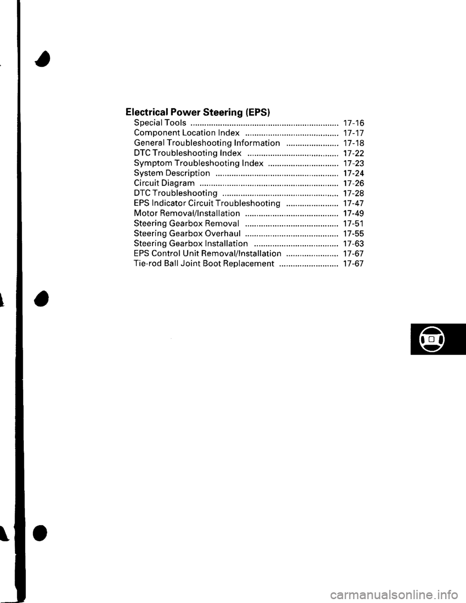
Electrical Power Steering (EPSI
SpecialTools ............. 17 -16
Component Location Index ......................................... 17-17
General Troubleshooting Information ....................... 17-18
DTC Troubleshooting Index .............. 17-22
Symptom Troubleshooting Index ............................... 17 -23
System Description ................. ........... 17-24
Circuit Diagram ......... 17-26
DTC Troubleshooting ............... .......... 17-28
EPS lndicator Circuit Troubleshooting ....................... 17-47
Motor Removal/lnstallation ............... 17-49
Steering Gearbox Removal ............... 17-51
Steering Gearbox Overhaul ............... 17-55
Steering Gearbox Installation ........... 17-63
EPS Control Unit Remova l/lnsta llation ....................... 17-67
Tie-rod Ball Joint Boot Replacement .......................... 17-67
Page 508 of 1139
![HONDA CIVIC 2003 7.G Workshop Manual Component Location Index
UNDER.HOODFUSE/RELAY BOX
EPS CONTROL UNITEPS Control Unit Removal/lnstallation,page 17 -67
UNDER.DASH FUSE/RELAY BOX
-,/.,....
.,i,
X ]
DATA LINK CONNECTOR I16P)
TOROUE SENS HONDA CIVIC 2003 7.G Workshop Manual Component Location Index
UNDER.HOODFUSE/RELAY BOX
EPS CONTROL UNITEPS Control Unit Removal/lnstallation,page 17 -67
UNDER.DASH FUSE/RELAY BOX
-,/.,....
.,i,
X ]
DATA LINK CONNECTOR I16P)
TOROUE SENS](/img/13/5744/w960_5744-507.png)
Component Location Index
UNDER.HOODFUSE/RELAY BOX
EPS CONTROL UNITEPS Control Unit Removal/lnstallation,page 17 -67
UNDER.DASH FUSE/RELAY BOX
-,'/.,....
'.,i,
X ]
DATA LINK CONNECTOR I16P)
TOROUE SENSOR
STEERING GEARBOXSteering Gearbox Removal, page 17-51Steering Gearbox Overhaul, page 17-55Steering Gearbox Installation, page 17-63
Removal/lnstallation,page l7-49
GAUGE ASSEMBLY
MOTOR
17-17
Page 509 of 1139
EPS Components
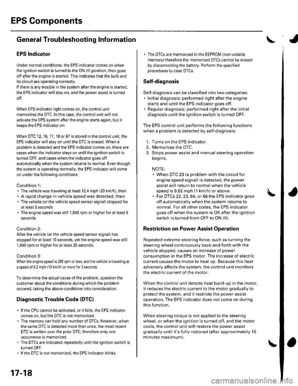
aGeneral Troubleshooting Information
EPS Indicator
Under normal conditions, the EPS indicator comes on when
the ignitlon switch is turned to the ON (ll) position, then goes
off after the engine is started. This indicates that the bulb and
its circuit are operating correctly.
lf there is any trouble in the system after the engine is started,
the EPS indicator will stay on, and the power assist is turned
off.
When EPS indicator light comes on, the control unit
memorizes the DTC. In this case, the control unit will not
activate the EPS system after the engine starts again, but it
keeps the EPS indicator on.
When DTC 12, 16, 17, 18 or 67 is stored in the control unit, the
EPS indicator will stay on until the DTC is erased. When a
problem is detected and the EPS indicator comes on, there are
cases when the indicator stays on untilthe ignition switch is
turned 0FF, and cases when the indicator goes off
automatically when the system returns to normal. Even though
the system is operating normally, the EPS indicator will come
on under the following conditions:
Condition '1:
. The vehicle was traveling at least 12.4 mph (20 km/h), then. A rapid change in vehicle speed was detected, then. The vehicle (or the vehicle speed sensor signal) stopped for
at least 5 seconds. The engine speed was still 'l,640rpmorhigherforatleastS
seconds
Condition 2:
After the vehicle (or the vehicle speed sensor signal) has
stopped for at least 10 seconds, yet the engine speed was still
1,640 rpm or higherfor at least 20 seconds.
Condition 3:
When the engine speed is 280 rpm or less, and the vehicle is traveling at
a speed of 6,2 mph (10 km/h) or more for 3 seconds.
To determine the actual cause ofthe problem, question the
customer about the conditions during which the problem
occured, taking the above conditions into consideration.
Diagnostic Trouble Code (DTCI
. lf the CPU cannot be activated, or itfails,the EPS indicator
comes on, but the DTC is not memorized.. The memory can hold any number of DTCS. However, when
the same DTC is detected more than once, the most recent
DTC is written over the prior DTC, therefore only one
occurrence is memorized.. The DTCS are indicated repeatedly untilthe ignition switch is
turned OFF.. lf the DTC is not memorized,the EPS indicator blinks.
. The DTCS are memorized in the EEPRO| (non-volatile
memory) therefore the memorized DTCS cannot be erased
by disconnecting the battery. Perform the specified
procedures to clear DTCS.
Self-diagnosis
Self-diagnosis can be classified into two categories:.Initial diagnosis: performed right after the engine
starts and until the EPS indicator goes off.. Regular diagnosis: performed right after the initial
diagnosis until the ignition switch is turned OFF.
The EPS control unit performs the following functions
when a problem is detected by self-diagnosis;
'1. Turns on the EPS indicator.
2. Memorizes the DTC.
3. Stops power assist and manual steering operation
begrns.
NOTE:. When DTC 23 (a problem with the circuit for
engine speed signal) is detected, the power
assist will return to normal when the vehicle
speed is 0.62 mph (1 km/h) or above.. Fot DfCs 22,23, 64, or 66 the EPS indicator goes
off automatically when the system relurns to
normal. For all other codes, the EPS indicator
goes off when the system is OK after the ignition
switch is turned from OFF to ON (ll).
Restriction on Power Assist Operation
Repeated extreme steering force. such as turning the
steering wheel continuously back-and-forth with the
vehicle stopped, causes an increase of power
consumption in the EPS motor. The increase of electric
current causes the motor to heat up. Because this heat
adversely affects the system, the control unit monitors
the electric current of the motor.
When the control unit detects heat build-up in the motor,
it reduces the electric current to the motor gradually to
protect the system, and it restricts the power assist
operation. The EPS indicator does not come on during
this function.
When steering torque is not applied to the steering
wheel, or when the ignition is turned off, and the motor
cools, the control unit will restore the power assist
gradually until it's fully restored (after approximately 15
minutes maximum).
17-18
Page 513 of 1139
EPS Components
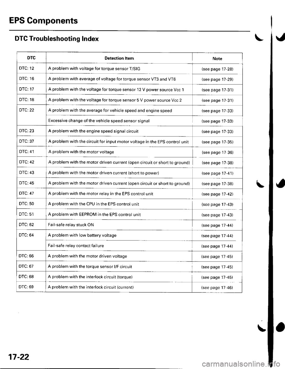
DTC Troubleshooting Index
DTCDetection ltemNote
DTC; 12A problem with voltage for torque sensor T/SlG(see page 17-28)
DTC: 16A problem with average of voltage for torque sensor VT3 and VT6(see page 17-29)
DTC: 17A problem with the voltage for torque sensor 12 V power source Vcc 1(see page 17-31)
DTC: 18A problem with the voltage for torque sensor 5 V power source Vcc 2(see page 17-31)
DfC:22A problem with the average for vehicle speed and engine speed(see page 17-33)
Excessive change of the vehicle speed sensor signal{see page 17-33)
DTC: 23A problem with the engine speed signal circuit(see page 17-33)
DTC: 37A problem with the circuit for input motor voltage in the EPS control unit(see page 17-35)
DTC: 41A problem with the motor voltage(see page 17 36)
DfC: 42A problem with the motor driven current (open circuit or short to grounol(see page '17-38)
DTC: 43A problem with the motor driven current (short to power)(see page 17-41)
DTC: 45A problem with the motor driven current (open circuit or short to grou nol(see page 17-38)
DfC: 47A problem with the motor relav in the EPS control unit{see page 17-42)
DTC: 50A problem with the CPU in the EPS control unit(see page 17-43)
DTC: 51A problem with EEPROM in the EPS control unlt(see page 17-43)
DTC: 62Fail-safe relay stuck ON(see page 17-44)
DTC: 64A problem with low battery voltage
Fail-safe relay contact failure
(see page 17-44)
(see page 17-44)
DTC: 66A problem with the motor driven voltage{see page 17 45)
DTC: 67A problem with the torque sensor l/F circuit(see page 17'45)
DTC: 68A problem with the interlock circuit (torque){see page 17-45)
DTC: 69A problem with the interlock circuit (current)(see page 17-46)
17-22
Page 514 of 1139
![HONDA CIVIC 2003 7.G Workshop Manual Symptom Troubleshooting Index
SymptomDiagnostic procedureAlso check fo]
EPS indicator does not
come on
EPS lndicator Circuit Troubleshooting (see page 17-47)
EPS indicator does not go
off and no DTC i HONDA CIVIC 2003 7.G Workshop Manual Symptom Troubleshooting Index
SymptomDiagnostic procedureAlso check fo]
EPS indicator does not
come on
EPS lndicator Circuit Troubleshooting (see page 17-47)
EPS indicator does not go
off and no DTC i](/img/13/5744/w960_5744-513.png)
Symptom Troubleshooting Index
SymptomDiagnostic procedureAlso check fo]
EPS indicator does not
come on
EPS lndicator Circuit Troubleshooting (see page 17-47)
EPS indicator does not go
off and no DTC is stored
EPS Indicator Circuit Troubleshooting (see page 17-47)
EPS indicator does not stay
on, no DTC is stored, and
there is no power assist
1. Check the motor wires between the EPS control unit and the
motor for a short to ground. Repair as needed.
2. lf the motor wires are OK, replace the steering gearbox
{short in the motor).
17-23
Page 515 of 1139
EPS Gomponents
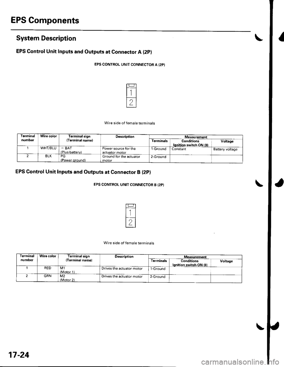
System Description
EPS Gontrol Unit Inputs and Outputs at Connector A (2pl
EPS CONTROL UNIT CONNECTOR A {2P)
Wire side of female terminals
EPS Control Unit Inputs and Outputs at Connector B (2P)
EPS CONTROL UNIT CONNECTOB B {2P}
Wire side of female terminals
TermanalnumbolWire colorTerminal sign(Terminal namelDescriptionMeasurementTerminalsConditionslqnitiqr switch ON (lllVoltage
WHT/BLU-' BAT(Plus bafterv)Power source for theactuator motorl GroundConstantBattery voltage
28LKPGGround forthe actuator2-Ground
TerminalnumDerWire cololTerminalsign{Te.mioalname)DescriptionMeasuremenlTerminalsConditionslqnition switch ON llllVoltage
1REDM1(Motor 1Drives lhe actuator motor1-Ground
2GRNM2Drives the actuator motor2'Ground
17-24