Control HONDA CIVIC 2003 7.G Repair Manual
[x] Cancel search | Manufacturer: HONDA, Model Year: 2003, Model line: CIVIC, Model: HONDA CIVIC 2003 7.GPages: 1139, PDF Size: 28.19 MB
Page 235 of 1139
Fuel and Emissions Systems
(
(
(
System Descriptions (cont'dl
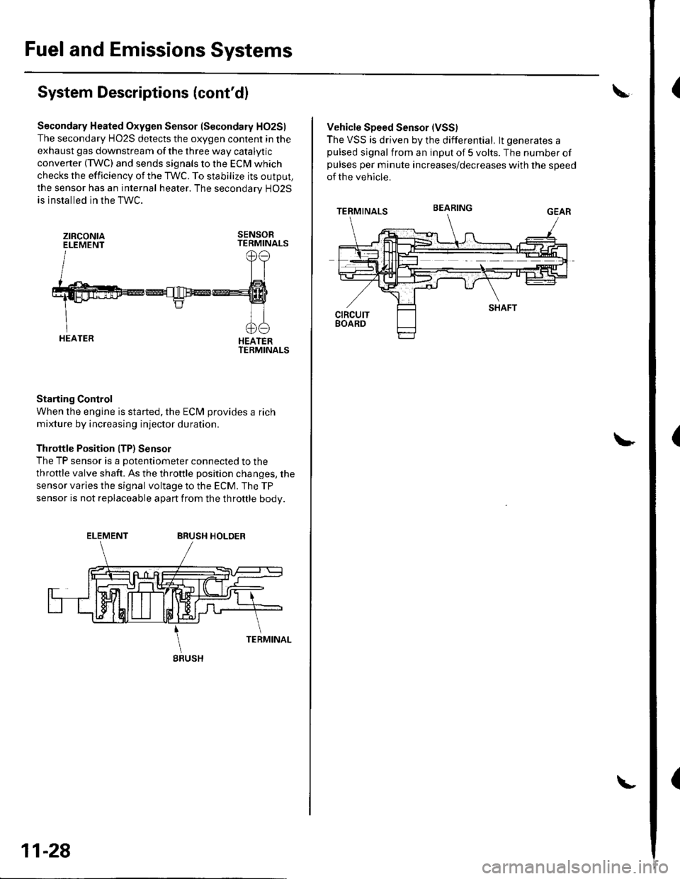
Secondary Heated Oxygen Sensor (Secondary HO2S)
The secondary HO2S detects the oxygen content in the
exhaust gas downstream of the three way catalytic
converter (TWC) and sends signals to the ECM which
checks the efficiency of the TWC. To stabilize its output,
the sensor has an internal heater. The secondarv HO2S
is installed in the TWC.
ztRcoNtaELEMENTSENSORTERMINALS
HEATERTERMINALS
Starting Control
When the engine is started, the ECM provides a rich
mixture by increasing injector duration.
Throttle Position ITP) Sensor
The TP sensor is a potentiometer connected to the
throttle valve shaft. As the throttle position changes, the
sensor varies the signal voltage to the ECM. The TP
sensor is not replaceable apart from the throftle body.
ELEMENTBRUSH HOLDER
gRUSH
11-28
Vehicle Speed Sensor (VSS)
The VSS is driven by the differential. lt generates apulsed signal from an input of 5 volts. The number ofpulses per minute increases/decreases with the speed
of the vehicle.
BEARING
Page 236 of 1139
wEc/wc
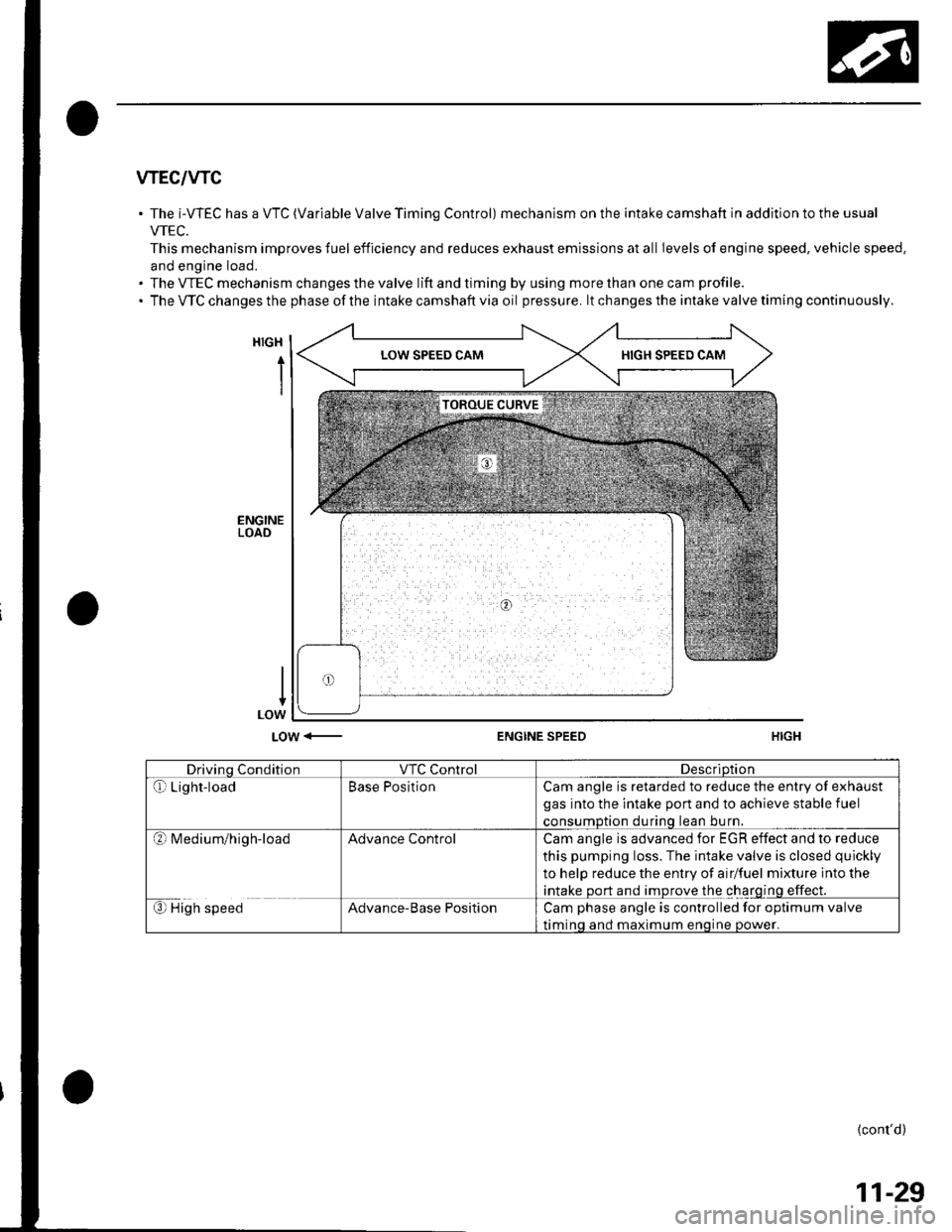
The i-WEC has a VTC (Variable Valve Timing Control) mechanism on the intake camshaft in addition to the usual
VTEC.
This mechanism improves fuel efficiency and reduces exhaust emissions at all Ievels of engine speed, vehicle speed.
and engine load.
The VTEC mechanism changes the valve lift and timing by using more than one cam profile.
The VTC changes the phase of the intake camshaft via oil pressure. lt changes the intake valve timing continuously.
HIGH
i
LOW <-ENGINE SPEED
Drivino ConditionVTC ControlDescriDtion
Qr Light-loadBase PositionCam angle is retarded to reduce the entry of exhaust
gas into the intake port and to achieve stable fuel
consumDtion durinq lean bu rn.
?l M ed iu m/h ig h-loadAdvance ControlCam angle is advanced for EGR effect and to reduce
this pumping loss. The intake valve is closed quickly
to help reduce the entry of airlfuel mixture into the
intake port and improve the charging effect.
€) High speedAdvance-Base PositionCam phase angle is controlled for optimum valve
timinq and maximum enoine oower.
{cont'd)
11-29
Page 237 of 1139
Fuel and Emissions Systems
(System Descriptions (cont'dl
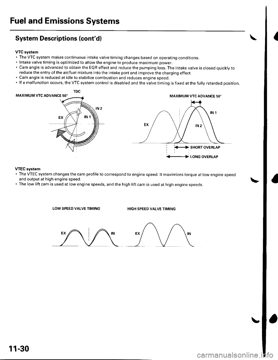
VTC system. The VTC system makes continuous intake valve timing changes based on operating conditions.. Intake valve timing is optimized to allow the engine to produce maximum power.'CamangleisadvancedtoobtaintheEGReffectandreducethepumpingloss.Theintakevalveisclosedquicklyto
reduce the entry of the airlfuel mixture into the intake port and improve the charging effect.. Cam angle is reduced at idle to stabilize combustion and reduces engine speed.'lfamalfunctionoccurs,theVTCsystemcontrol is disabled and the valve timing is fixed at the fully retarded position.
MAXIMUM VTC ADVANCE 50'
i l(-4 sHoRT oVERLAP
'+-|l LoNG oVERLAP
VTEC system' The VTEC system changes the cam profile to correspond to engine speed. lt maximizes torque at low engine speedand output at high engine speed.. The low lift cam is used at low engine speeds, and the high lift cam is used at high engine speeds.
LOW SPEED VALVE TIMINGHIGH SPEED VALVE TIMING
TDC
MAXIMUM VTC ADVANCE 50'
11-30
Page 239 of 1139
Fuel and Emissions Systems
(
{
System Descriptions (cont'd)
ldle Control System
When the engine is cold, the Ay'C compressor is on, the
transmission is in gear, the brake pedal is pressed. thepower steering load is high, or the alternator is
charging, the ECIM controls current to the ldle Air
Control (lAC) valve to maintain the correct idle speed.
Refer to the System Diagram to see the functional
layout of the system.
Brake Pedal Position Switch
The brake pedal position switch signals the ECM when
the brake pedal is oressed.
Electrical Power Steering (EPS) Senser
The EPS sensor signals the ECM when the power
steering load is high.
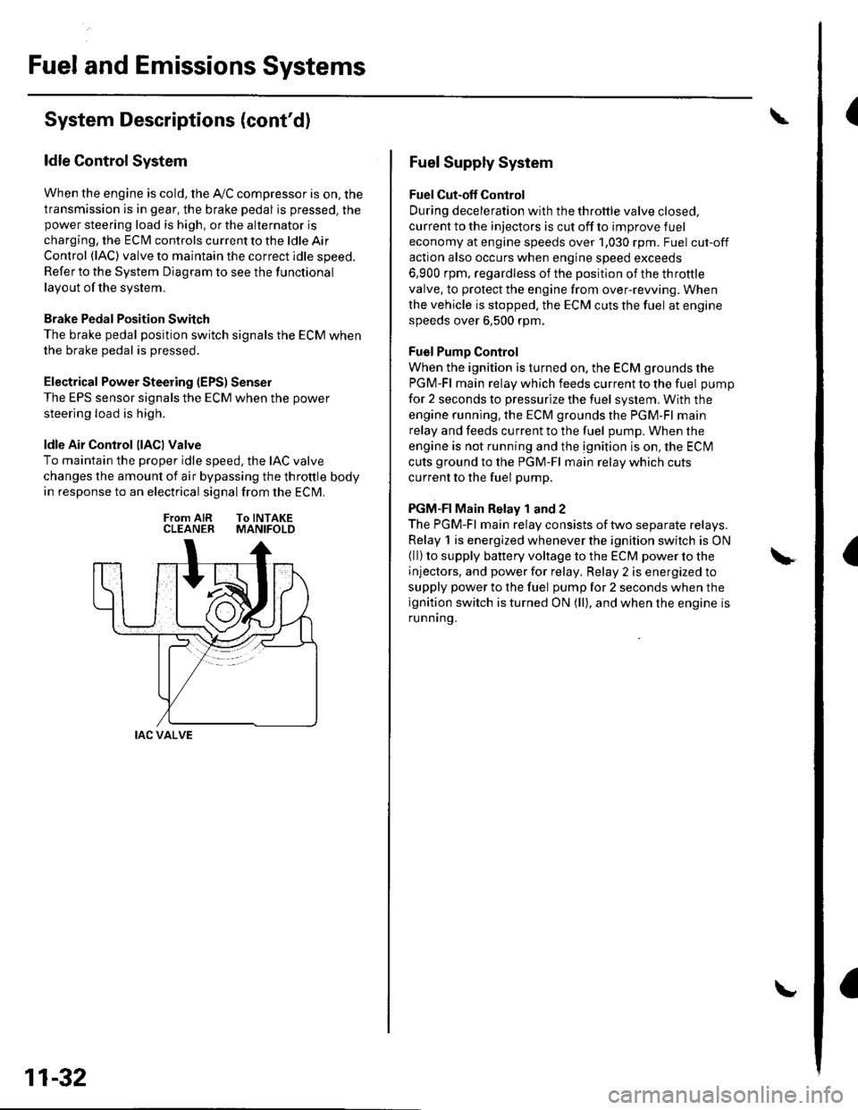
ldle Air Control llACl Valve
To maintain the proper idle speed, the IAC valve
changes the amount of air bypassing the throttle body
in response to an electrical signal from the ECM.
From AIR To INTAKECLEANER MANIFOLD
IAC VALVE
11-32
Fuel Supply System
Fuel Cut-off Control
During deceleration with the throttle valve closed,
current to the injectors is cut off to improve fuel
economy at engine speeds over 1,030 rpm. Fuel cut-off
action also occurs when engine speed exceeds
6,900 rpm, regardless of the position of the throttle
valve, to protect the engine from over-rewing. When
the vehicle is stopped. the ECM cuts the fuel at engine
speeds over 6,500 rpm.
Fuel Pump Control
When the ignition is turned on, the ECM grounds the
PGM-Fl main relay which feeds current to the fuel pump
for 2 seconds to pressurize the fuel system, With the
engine running. the ECM grounds the PGM-Fl main
relay and feeds current to the fuel pump. When the
engine is not running and the ignition is on, the ECI\4
cuts ground to the PGM-Fl main relay which cuts
current to the fuel pump.
PGM-FI Main Relay 1 and 2
The PGM-Fl main relay consists of two separate relays.
Relay 1 is energized whenever the ignition switch is ON(ll) to supply battery voltage to the ECM power to the
injectors, and power for relay, Relay 2 is energized to
supply power to the fuel pump for 2 seconds when the
ignition switch is turned ON (ll), and when the engine is
runnrng.
Page 240 of 1139
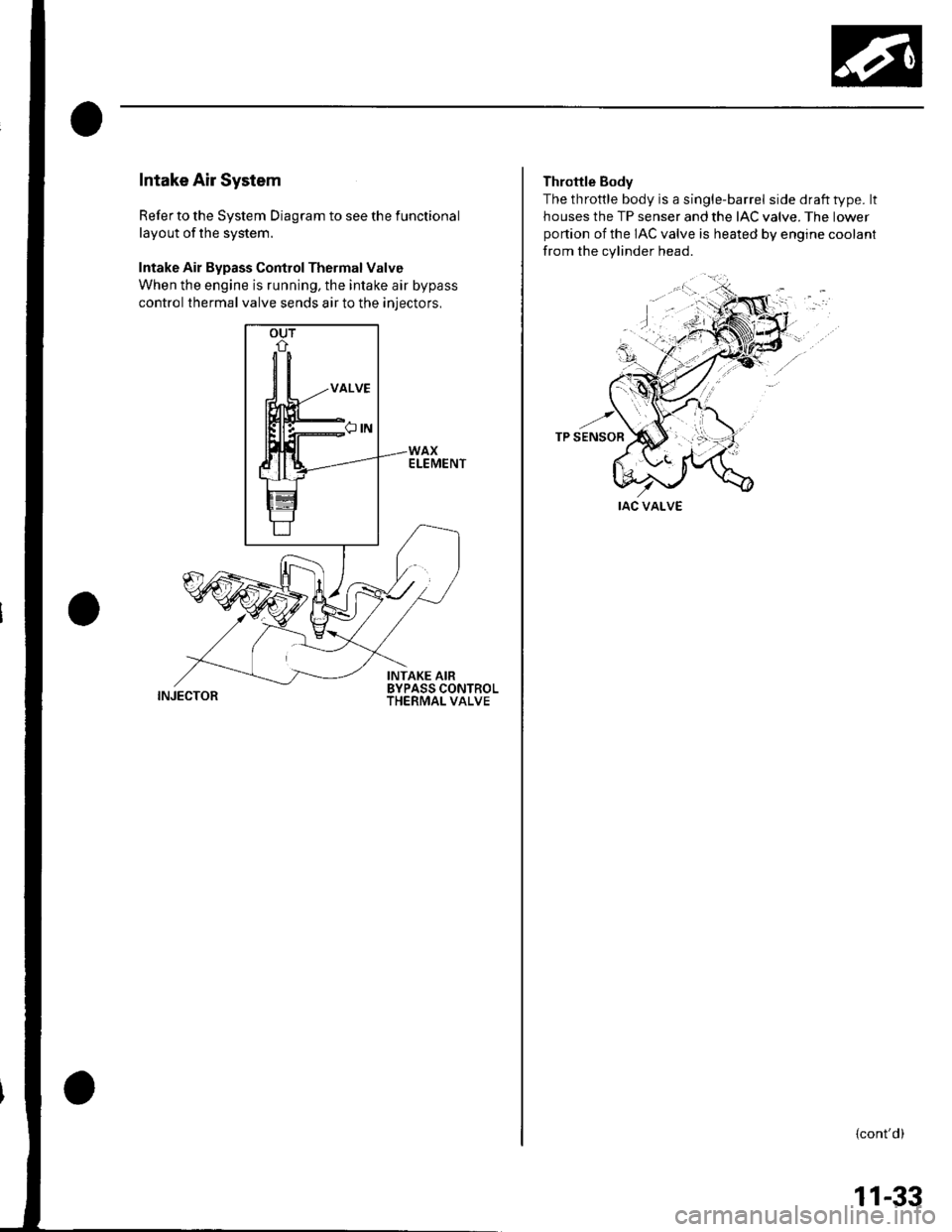
Intake Air System
Refer to the System Diagram to see the functional
layout of the system.
Intake Air Bypass Control Thermal Valve
When the engine is running, the intake air bypass
control thermal valve sends air to the iniectors,
INJECTOR
Throttle Body
The throttle body is a single-barrel side draft type. lt
houses the TP senser and the IAC valve. The lower
portion of the IAC valve is heated by engine coolant
from the cylinder head.
IAC VALVE
{cont'd)
11-33
Page 242 of 1139
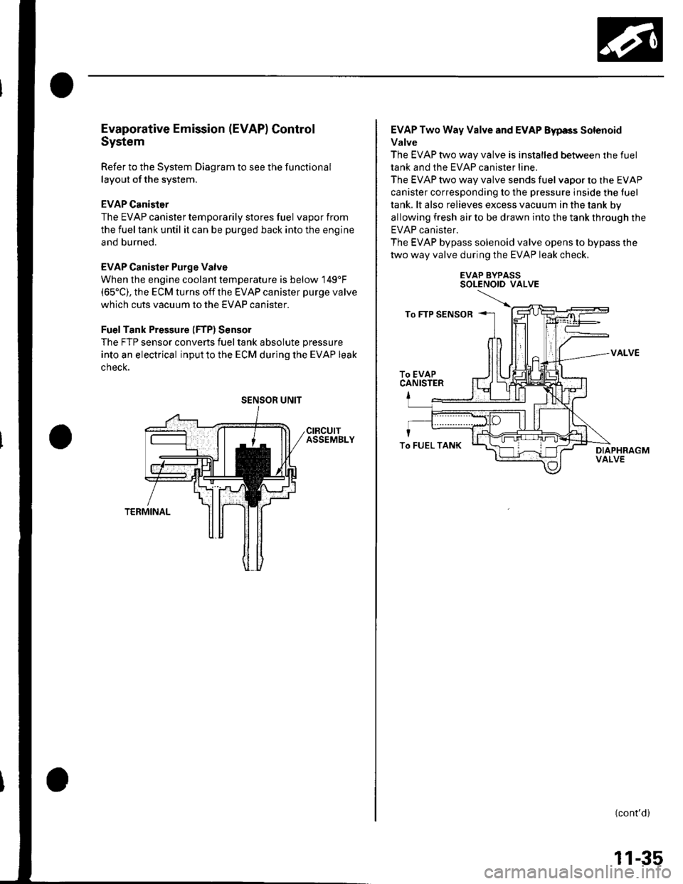
Evaporative Emission (EVAPI Control
System
Refer to the System Diagram to see the functional
layout of the system.
EVAP Canister
The EVAP canister temporarily stores fuel vapor from
the fuel tank until it can be purged back into the engine
and burned.
EVAP Canister Purge Valve
When the engine coolant temperatu re is below 149'F(65'C), the ECM turns off the EVAP canister purge valve
which cuts vacuum to the EVAP canister.
FuelTank Pressure (FTP) Sensor
The FTP sensor converts fueltank absolute pressure
into an electrical inputto the ECM during the EVAP leak
cnecK.
SENSOR UNIT
EVAP Two Way Valve and EVAP Eyp8s Solenoid
Valve
The EVAP two way valve is installed between the fuel
tank and the EVAP canister line.
The EVAP two way valve sends fuel vapor to the EVAP
canister corresponding to the pressure inside the tuel
tank. lt also relieves excess vacuum in the tank by
allowing fresh air to be drawn into the tank through the
EVAP canister.
The EVAP bypass solenoid valve opens to bypass the
two way valve during the EVAP leak check.
EVAP BYPASSSOLENOID VALVE
VALVE
(cont'd)
To FUEL TANK
11-35
Page 243 of 1139
Fuel and Emissions Systems
System Descriptions (cont'dl
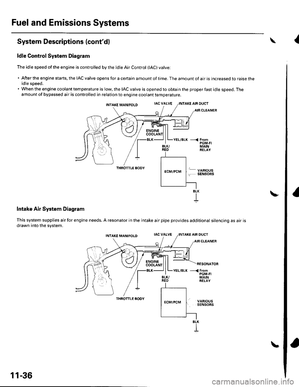
ldle Control System Diagram
The idle speed of the engine is controlled by the ldle Air Control (lAC) varve:
'Aftertheenginestarts,theIACvalveopensforacertainamountoftime.Theamountofairisincreasedtoraisethe
idle sDeed.. When the engine coolant temperature is low, the IAC valve is opened to obtain the proper fast idle speed. Theamount of bypassed air is controlled in relation to engine coolant temperature.
INTAKE MANIFOLDIAC VALVEAKE AIR DUCT
CLEANER
\
BLK/REO
YEL/BLK ---< FromPGM.FIMAINRELAY
THROTTLE AODY
Intake Air System Diagram
This system supplies air for engine needs. A resonator in the intake air
drawn into the svstem.
VARIOUSSENSOnS
pipe provides additional silencing as air is
THROTTLE AODYVARIOUSSENSORS
BLK
BLK
I
11-36
{
Page 244 of 1139
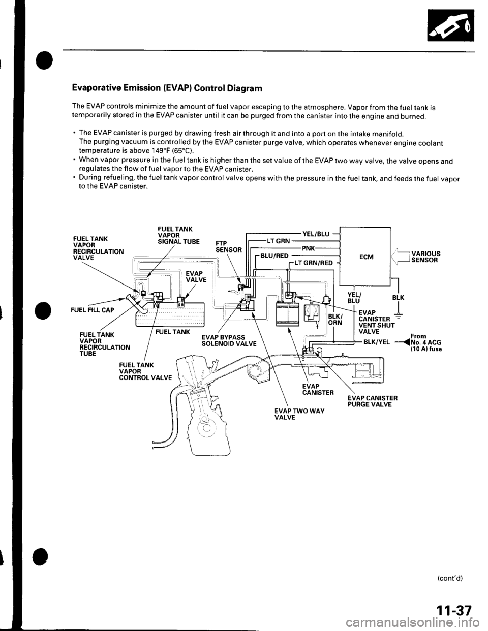
Evaporative Emission (EVAPI Control Diagram
The EVAP controls minimize the amount of fuel vapor escaping to the atmosphere. Vapor from the fuel tanK rstemporarily stored in the EVAP canister until it can be purged from the canister into the engine and burneo.
. The EVAP canister is purged by drawing fresh air through it and into a port on the intake manifold.The purging vacuum is controlled by the EVAP canister purge valve, which operates whenever engine cootanttemperature is above 149'F (65"C).
'WhenvaporpressureinthefueltankishigherthanthesetvalueoftheEVAPtwowayvalve,thevalveopensano
regulates the flow of fuel vapor to the EVAP canister.'Duringrefueling,thefueltankvaporcontrol valve opens with the pressure in the fuel tank, and feeds the fuel vaDorto the EVAP canister.
FUEL TANKVAPORRECIRCULATIONVALVE
FUEL TANKVAPORSIGNAL TUBE
BLU/RED
FUEL FILL CAP
BLK
+EVAPCANISTER
FUEL TANKVENT SHUTVALVE
BLK/YELFrom--
EVAPCANISTER
EVAP TWO WAYVALVE
(cont'd)
11-37
Page 250 of 1139
![HONDA CIVIC 2003 7.G Repair Manual SECONDAFYH02S(s€NsoR 2l
m
tlilTPS€NSOR
--{=l
-{r I
CANISTER VEAITSHUTVALVE
t-_]
--lti lEVAP EYPASSsolENorD
To€PSCONTROLUNIT
CPU
GAUGE ASSEMBTY
(contd)
11-43 HONDA CIVIC 2003 7.G Repair Manual SECONDAFYH02S(s€NsoR 2l
m
tlilTPS€NSOR
--{=l
-{r I
CANISTER VEAITSHUTVALVE
t-_]
--lti lEVAP EYPASSsolENorD
To€PSCONTROLUNIT
CPU
GAUGE ASSEMBTY
(contd)
11-43](/img/13/5744/w960_5744-249.png)
SECONDAFYH02S(s€NsoR 2l
m
tlilTPS€NSOR
'--{=l
-{r I
CANISTER VEAITSHUTVALVE
t-_]
--lti lEVAP EYPASSsolENorD
To€PSCONTROLUNIT
CPU
GAUGE ASSEMBTY
(cont'd)
11-43
Page 254 of 1139
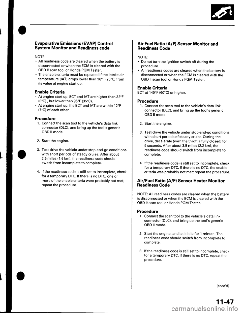
Evaporative Emissions (EVAP) Control
System Monitor and Readiness code
NOTE:
All readiness code are cleared when the batterV is
disconnected or when the ECM is cleared with the
OBD ll scan tool or Honda PGM Tester.
The enable criteria must be repeated if the intake air
temperature (lAT) drops lower than 36'F (20"C) from
its value at engine $an up.
Enable Criteria
At engine start up, ECT and IAT are higher than 32'F(0"C) , but lower than 95'F (35"C).
At engine start up, the ECT and IAT are within 12'F(7'C) of each other.
Procedure
1. Connect the scan tool to the vehicle's data link
connector (DLC), and bring up the tool's generic
OBD ll mode.
2. Start the engine.
3. Test-drive the vehicle under stop-and-go conditions
with short periods of steady cruise. After about
2.5 miles (1.6 km), the readiness code should
switch f rom incomplete to complete.
4. lf the readinesscode isstill setto incomplete, check
for a temporary DTC. lf there is no DTC, one or
more of the enable criteria were probably not met;
repeat the procedure.
Air Fuel Ratio (A/Fl Sensor Monitor and
Readiness Code
NOTE:. Do not turn the ignition switch off during the
orocedure.. All readiness codes are cleared when the baftery is
disconnected or when the ECM is cleared with the
OBD ll scan tool or Honda PGM Tester.
Enable Criteria
ECT at 140'F (60"C) or higher.
Procedure
1. Connect the scan toolto the vehicle's data link
connector (DLC), and bring up the tool's generic
OBD ll mode.
2. Start the engine.
3. Test-drive the vehicle under stop-and-go conditions
with short periods of steady cruise. During the
drive, decelerate (wirh the throttle fully closed) for
5 seconds. After about 3.5 miles (2.2 km). the
readiness code should switch from incomDlete to
complete.
4. lfthereadinesscodeisstill set to incomplete, check
for a temporary DTC. lfthere is no DTC, the enable
criteria was probably not meU repeat the procedure.
Air/Fuel Ratio (A/Fl Sensor Heater Monitor
Readiness Code
NOTE; All readiness codes are cleared when the battery
is disconnected or when the ECM is cleared with the
OBD ll scan tool or Honda PGM Tester,
Procedure'1. Connect the scan tool to the vehicle's data link
connector {DLC), and bring up the tool's generic
OBD ll mode.
2. Start the engine, and let it idle for 1 minute. The
readiness code should switch from incomplete to
comDlete.
3. lf the readiness code is still set to incomplete, check
for a temporary DTC. lf there is no DTC, repeat theproceoure.
(cont'd)
11-47