Control HONDA CIVIC 2003 7.G Manual PDF
[x] Cancel search | Manufacturer: HONDA, Model Year: 2003, Model line: CIVIC, Model: HONDA CIVIC 2003 7.GPages: 1139, PDF Size: 28.19 MB
Page 255 of 1139
Fuel and Emissions Systems
a
a
How to Set Readiness Codes (cont'd)
Misfire Monitor and Readiness Code
. This readiness code is always set to available
because misfiring is continuously monitored.. l\4onitoring pauses, and the misfire counter resets, if
the vehicle is driven over a rough road.. Monitoring also pauses, and the misfire counter
holds at its current value. if the throttle position
changes more than a predetermined value, or if
driving conditions fall outside the range of any
related enable criteria,
Fuel System Monitor and Readiness Code
. This readiness code is always setto available
because the fuel system is continuously monitored
during closed loop operation.. Monitoring pauses when the catalytic converter,
EVAP control system, and Ay'F sensor monitors are
active.. Monitoring also pauses when any related enable
criteria are not being met. Monitoring resumes when
lhe enable criteria is again being met.
Comprehensive Component Monitor and
Readiness Code
This readiness code is always set to available because
the comprehensive component monitor is continuously
running whenever the engine is cranking or running.
11-48
\-
L
Page 258 of 1139
'}
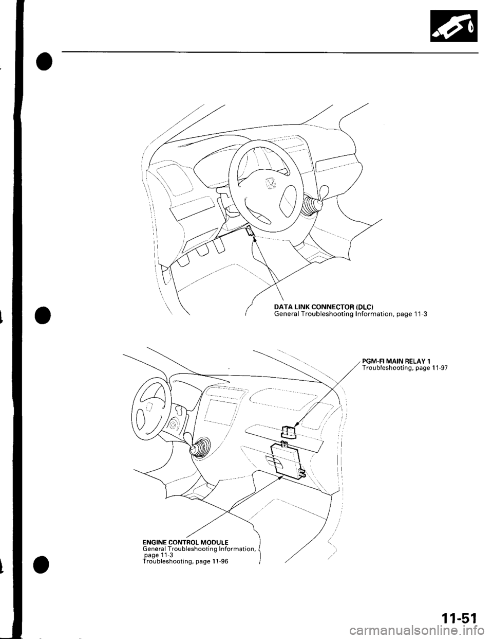
DATA LINK CONNECTOR IDLCIGeneral Troubleshooting Information, page 1 l 3
PGM.FI MAIN RELAY 1Troubleshooting, page 1 1-97
ENGINE CONTROL MODULEGeneral Troubleshootin g Information,page 11 3Troubleshooting, page I 1-96
11-51
Page 271 of 1139
PGM-FI System
aDTG Troubleshootang (cont'dl
DTC P0128: Cooling System Malfunction
NOTE; lf the DTCS listed below are stored at the same
time as DTC P0128. troubleshoot those DTCS first, thenrecheck for P0128.
P0107, P0108, P1128, P1129: N4anifold absolutepressure (MAP) sensor
P] I06, P1 107, P1 108: Barometric pressure (BARO)
sensor
P1259: VTEC system
P01 16, P01 17, P01 18: Engine coolant temperature (ECT)
sensor
P01 12, P01 13: Intake air temperature (lAT) sensor
P0500: Vehicle speed sensor {VSS)P0335, P0336: Crankshaft position (CKP) sensor
P0300: Random misfire
P0301, P0302, P0303, P0304: No. 1, No. 2, No.3 or No.4
cylinder misfire
P0505: ldle control system malfunction
P1519: ldle air control (lAC)valve
DTC P0128 can occasionally set when the hood is
opened while the engine is running.
1. Check the engine coolant level
Is the engine coolant level low?
VES Refill the engine coolant. lf necessary, repair
the coolant leakage.l
NO Go to step 2.
2. Turn the ignition switch ON (ll), and make sure the
A,/C is off.
11-64
\
3. Check the radiator fan.
Does the tadiator fan keep running?
YES Checkthe rad iato r fan circuit (see page 10-
14), the radiator fan switch circuit (Short) (see page
10-'16), and the radiator fan switch (see page 10-17).
Also, inspect the ECT and IAT circuits and terminal
connections. lf the circuits, the switch, and the
connections are OK, update the ECI\4 if it does not
have the latest software. or substitute a known-good ECM, then recheck (see page 1 1-6). lf the
symptom/indication goes away with a known-good
ECM, replace the original ECM.I
NO Replace the thermostat (see page 10-8).1
Page 278 of 1139
DTC P0300: Random Misfire and Any Combination of the Following:
DTC P0301: No. 1 Cylinder Misfire
DTC P0302: No. 2 Cvlinder Misfire
DTC P0303: No, 3 Cvlinder Misfire
DTC P0304: No. 4 Cvlinder Misfire
NOTE:. lfthe misfiring is frequent enough to trigger detection of increased emissions during two consecutive driving cycles.
the MIL will come on, and DTC P0300 (and some comlrination of P0301 through P0304) will be stored.. lf the misfiring is frequent enough to damage the catalyst, the MIL will blink whenever the misfiring occurs, and OTC
P0300 (and some combination of P0301 through P0304) will be stored. When the misfirlng stops, the MIL will remain
on.
1. Troubleshoot the following DTCs first if any of them were stored along with the random misfire DTC(s):
P0'107, P0108, P1128, P1129r N4anifold absolute pressure (MAP) sensor
P0111. P0'172t Fuel svstem
P0335. P0336: Crankshaft position (CKP) sensor
P0505: ldle control system
P1 149, Pl 162, P1 163, P1 164, P 1 165: Air fuel ratio (Ay'F) sensor
P1259: VTEC system
P1361, P1362: Camshaft position (CMP) sensor B {Top dead center (TDC) sensor)
P1519: ldle air control (lAC) valve
2. Test-drive the vehicle to verify the symptom.
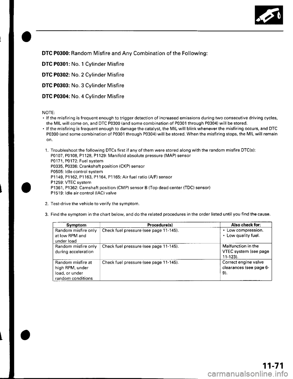
3. Findthesymptom inthechart below, and dothe related procedures in the order listed until you find the cause.
SymptomProcedure(slAlso check foi:
Random misfire only
at low RPM and
under load
Check fuel pressure (see page 1 1-145).. Low compressron.. Low quality fuel.
Random misfire only
du ring acceleration
Check fuel pressure (see page 11-145).Malfunction in the
VTEC system (see page
1'�t-123).
Random misfire at
high RPM, under
load, or under
random conditions
Check fuel pressure (see page 11-145).Correct engine valve
clearances (see page 6-
91.
11-71
Page 306 of 1139
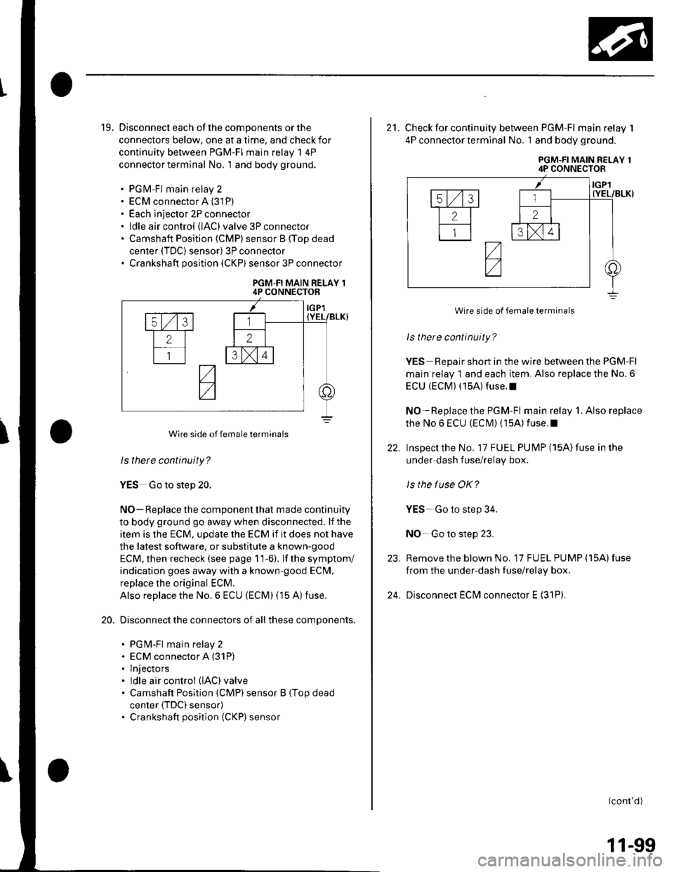
19. Disconnect each of the components or the
connectors below, one at a time, and check for
continuity between PGM-FI main relay 1 4P
connector terminal No. 1 and body ground.
. PGfvl-Fl main relay 2. ECM connector A (31P)
. Each injector 2P connector. ldle air control (lAC)valve 3P connector. Camshaft Position (CMP) sensor B (Top dead
center (TDC) sensor) 3P connector. Crankshaft position (CKP) sensor 3P connector
PGM-FI MAIN RELAY 14P CONNECTOR
ls thete continuity?
YES Go to step 20.
NO- Replace the component that made continuity
to body ground go away when disconnected. lf the
item is the ECM, update the ECM if it does not have
the latest software. or substitute a known-good
ECM, then recheck (see page 11-6). lf the symptom/
indication goes away with a known'good ECM,
replace the original ECM.
Also replace the No. 6 ECU (ECM) (15 A) fuse,
Disconnect the connectors of all these components.
. PGM-Fl main relay 2. ECM connector A (31P)
. lnjectors. ldle air control (lAC)valve
. Camshaft Position {CMP) sensor B (Top dead
center (TDC) sensor). Crankshaft position (CKP) sensor
20.
Wire side of female terminals
22.
21. Check for continuity between PGM-FI main relay 1
4P connector termlnal No. 1 and body ground.
PGM-FI MAIN RELAY 14P CONNECTOR
ls there continuity?
YES Repair short in the wire between the PGM-Fl
main relay 1 and each item. Also replace the No. 6
ECU {ECM) (15A) fuse.l
NO-Replace the PGM-Fl main relay 1. Also replace
the No 6 ECU {ECIM) (15A) f use. I
Inspectthe No. 17 FUEL PUI\4P (15A)fuse in the
under-dash f use/relay box.
ls the tuse OK?
YES Go to step 34.
NO Go to step 23.
Remove the blown No, 17 FU EL PUMP (15A) fuse
from the under-dash fuse/relay box.
Disconnect ECfvl connector E (31P).
(conr'd)
23.
24.
Wire side of female terminals
11-99
Page 324 of 1139
VTEC/VTC
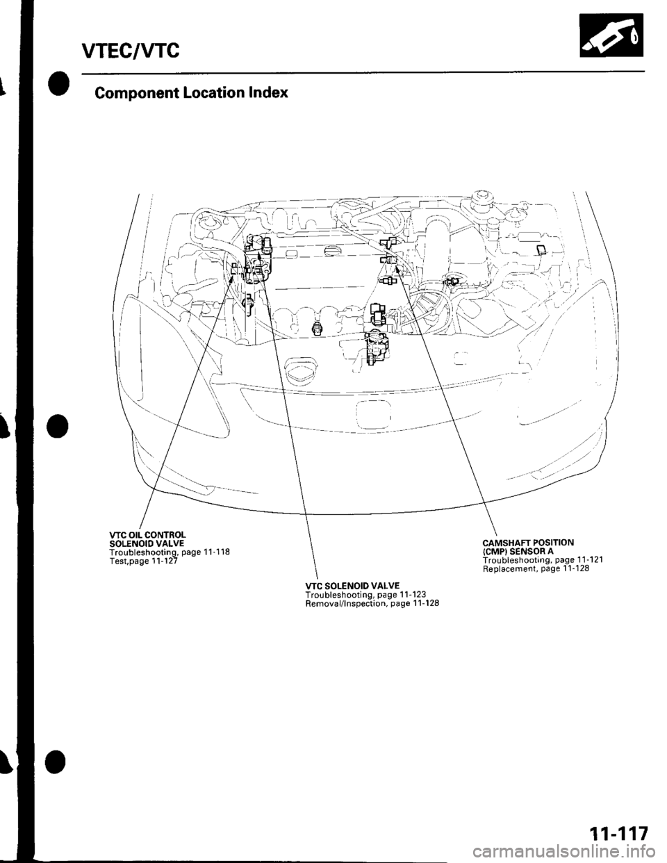
Component Location Index
VTC OIL CONTROLSOLENOID VALVETroubleshooting, page 1 1-118Test,page 11-'l27
-gl
:1
iai- r-:
@'-;'
;'l--i -
lt i..,,--tl
€)
,..
'- tt /
. -' '--'-
CAMSHAFT POSITIONICMPI SENSOR ATroubleshooting, page 1 1-121Replacement, Page l'!-128
VTC SOLENOID VALVETroubleshooting, page 1 1-123Removal/lnspection, page 1 1-128
11-117
Page 325 of 1139
VTEC/VTC
DTG Troubleshooting
DTC P0010: WC Oil Control Solenoid ValveMalfunction
1. Resetthe ECM (see page 11-4).
2. Start the engine. Hold the engine at 3,000 rpm withno load (in neutral) until the radiator fan comes on,
then let it idle.
3. Test-drive at a steady speed between 20-40 mph(30-60 km/h) for 10 minutes.
ls DTC P0010 indicated ?
YES Go to step 4.
NO- Intermittent failure, system is OK at this time.
Check for poor connections or loose terminals at
the VTC oil control solenoid valve and at theECM.I
4. Turn the ignition switch OFF.
5. Disconnect the ECM connector B {24P).
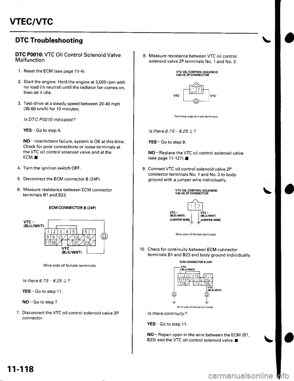
6. Measure resistance between ECrU connector
terminals B1 and 823.
ECM CONNECTOR B I24P)
Wire side of female terminals
ls there 6.75 8.25 Q ?
YES Go to step 1 1.
NO Go to step 7.
7. Disconnect the VTC oil control solenoidvalve2P
connector.
11-118
8. Measure resistance between VTC oil control
solenoid valve 2P terminals No. 1 and No. 2.
VTC OIL CONTAOL SOLENOIDVAI"VE 2P CONNECTOB
Termina sid6 otmate termina s
ls there 6.75 8.25 Q ?
YES-Go to step L
NO-Replace the VTC oil control solenoid valve(see page 11-1271.a
9. Connect VTC oil control solenoidvalve2P
connector terminals No. 1 and No. 2 to bodyground with a jumperwire individually.
wc otl coNTBoL sotENotoVALVE 2P CONNECTOR
-4-t1t2l
wc I lwc*tBr-K/wHT) | liELU/WHT)JUMPER WTREI IJUMPEn W|RE
Wire side of16male te.minats
10. Check for continuity between ECM connector
terminals B1 and 823 and body ground individually.
ls there continuity?
YES Go to step 11.
NO- Repair open in the wire between the ECM (B 1,
B23) and the VTC oil control solenoid valve.I
\
Page 326 of 1139
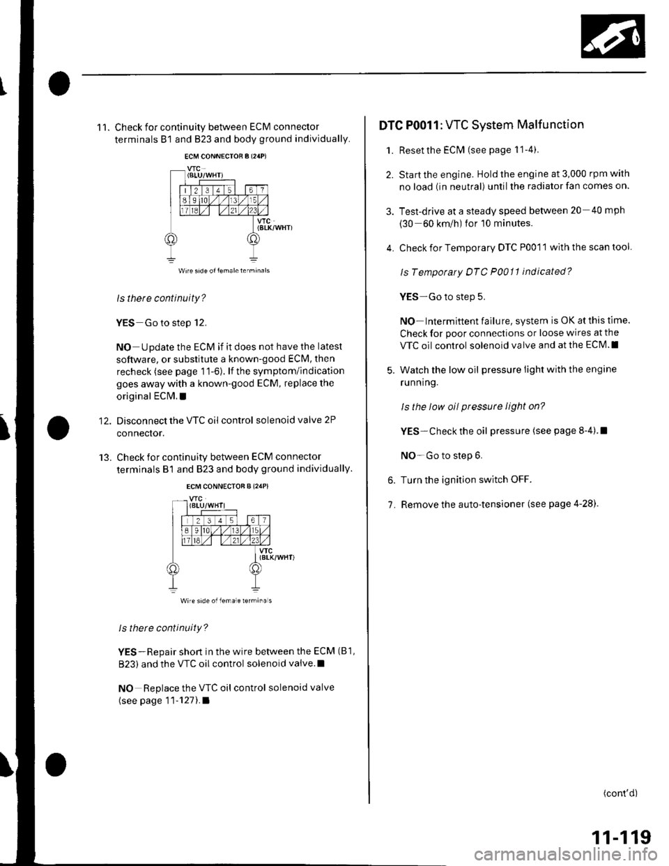
11. Check for continuity between ECM connector
terminals B1 and B23 and body ground individually.
VTC(BtK/WHT)
ls there continuity?
YES Go to step 12.
NO Update the ECM if it does not have the latest
software, or substitute a known-good ECM, then
recheck (see page 11-6). lf the symptom/indication
goes away with a known-good ECM, replace the
original EClvl. !
Disconnect the VTC oil control solenoid valve 2P
connector.
Check for continuity between ECM connector
terminals B1 and 823 and body ground individually.
12.
13.
vfc(8LK/WHT)
Wire side of female rermina s
ls there continuity?
YES-Repair short in the wire between the ECM (B1,
B23) and the VTC oil control solenoid valve.l
NO Replace the VTC oil control solenoid valve
(see page 11-1211.a
4.
DTC P0011: VTC System Malfunction
1. Reset the EClvl (see page 1 1-4).
2. Start the engine. Hold the engine at 3,000 rpm with
no load (in neutral) until the radiator fan comes on.
3. Test-drive at a steady speed between 20 40 mph
(30 60 km/h) for 10 minutes.
Check for Temporary DTC P0011 with the scan tool
ls Tempotaty DTC P0011 indicated?
YES-Go to step 5.
NO- Intermittent failu re, system is OK at this time.
Check for poor connections or loose wires at the
VTC oil control solenoid valve and at the ECM.I
Watch the low oil pressure light with the engine
ru n n ing.
ls the low oil pressute light on?
YES- Check the oil pressure (see page 8-4).I
NO-Go to step 6.
Turn the ignition switch OFF.
Remove the auto-tensioner (see page 4-28).
6.
7.
(cont'd)
11-119
Page 327 of 1139
VTEC/VTC
DTC Troubleshooting (cont'dl
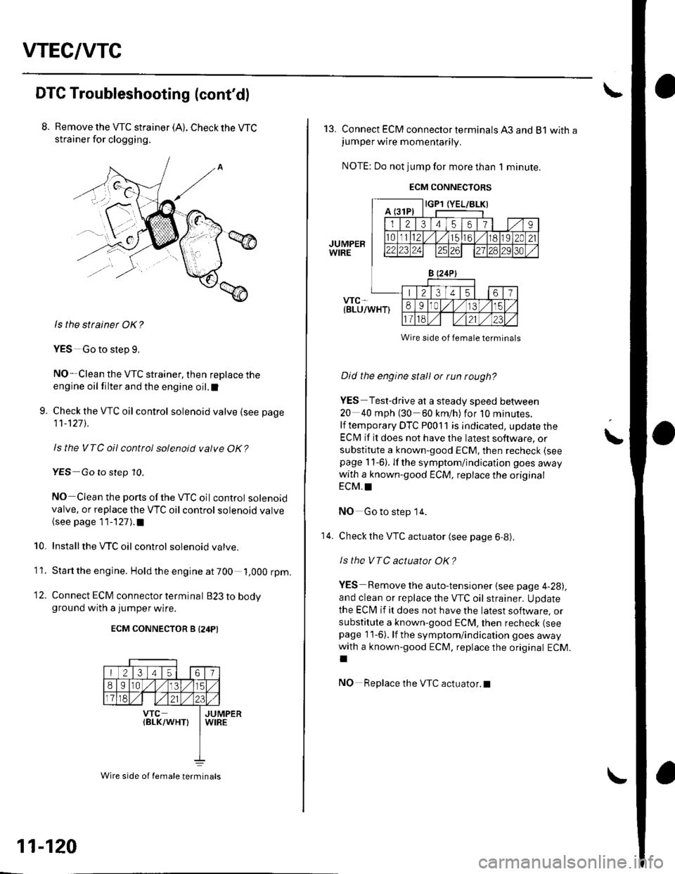
Remove the VTC strainer (A). Check the WC
strainer for clogging.
ls the strainet OK?
YES Go to step g.
NO-Clean the VTC strainer, then replace the
engine oil filter and the engine oil.l
9. Check the VTC oil control solenoidvalve {see page
11-127 ).
ls the VTC oilcontrol solenoid valve OK?
YES Go to step 10.
NO Clean the ports of the WC oil control solenoidvalve, or replace the VTC oil control solenoid valve
{see page 11-127).a
Installthe VTC oil control solenoid valve.
Start the engine. Hold the engine at 700 1,000 rpm.
12. Connect ECM connector terminal B23tobodvground with a jumper wire.
ECM CONNECTOR B {24PI
10.
11.
213 41567
8e l1a ,/1,/15
1181./l l./2123
vTc(BLK/WHT}JUMPERWIRE
11-120
Wire side of temale terminals
13. Connect ECM connector terminals A3 and 81 withajumper wire momentarily.
NOTE: Do not jump for more than 1 minute,
ECM CONNECTORS
Did the engine stall or run rough?
YES Test-drive at a steady speed between
20 40 mph (30 60 km/h) for 10 minutes.
lf temporary DTC P00'l 1 is indicated, update the
ECIVI if it does not have the latest software, or
substitute a known-good ECM, then recheck (see
page 11-6). lf the symptom/indication goes awaywith a known-good ECM, replace the original
ECM. !
NO Go to step 14.
Check the VTC actuator (see page 6,8).
ls the VTC actuatot OK?
YES Remove the auto-tensioner (see page 4-281,
and clean or replace the VTC oil strainer. Update
the ECI\4 if it does not have the latest software, orsubstitute a known-good ECM, then recheck (see
page 11-6). lf the symptom/indication goes awaywith a known-good ECM, replace the original ECM.
T
NO Replace the VTC actuator.t
\
14.
Wire side of female terminals
Page 329 of 1139
VTEC/VTC
10.
DTC Troubleshooting (cont'd)
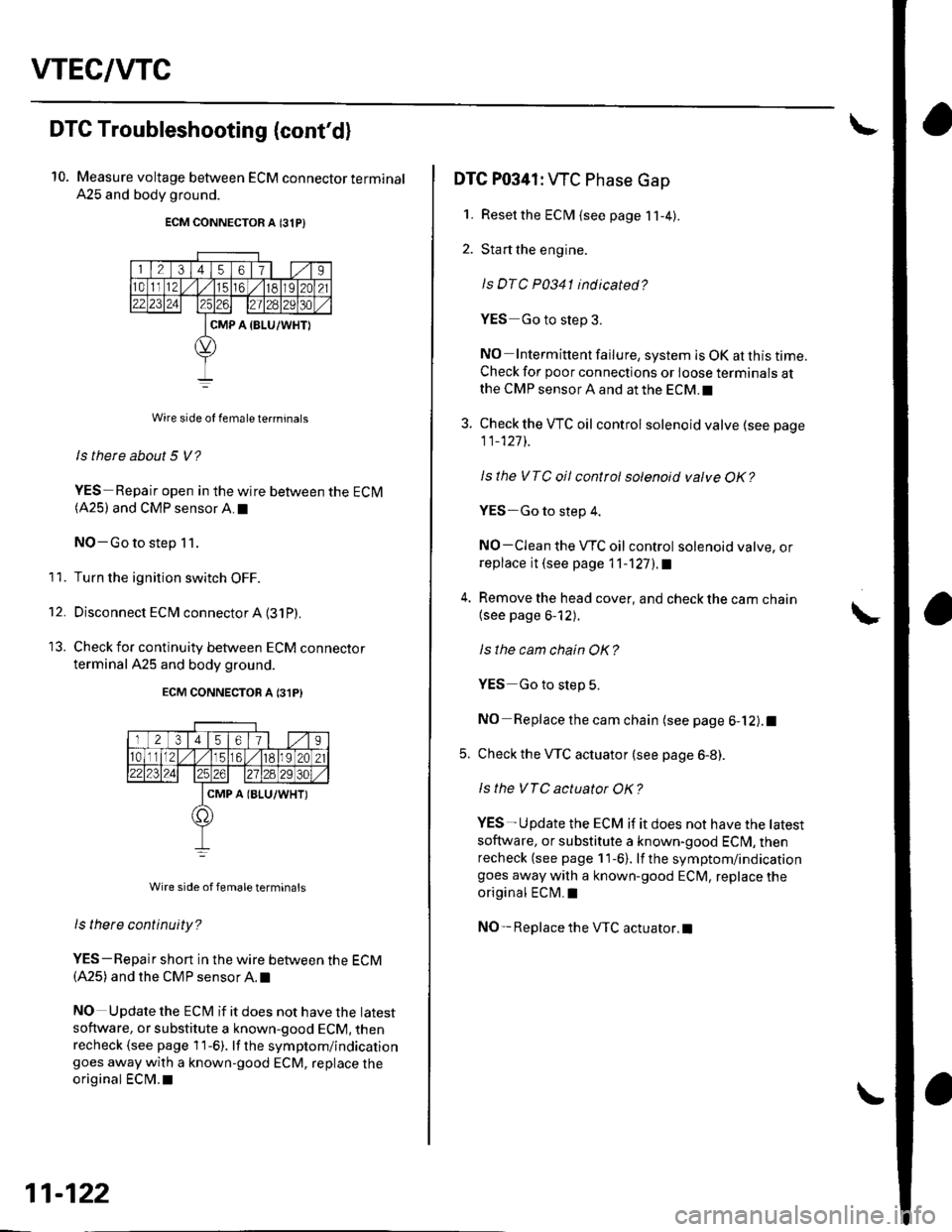
Measure voltage between ECM connector terminal
A25 and body ground.
ECM CONNECTOR A 131P)
Wire side of female te.minals
ls there about 5 V?
YES-Repair open in the wire between the ECM(A25) and CMP sensor A.I
NO-Go to step 11.
Turn the ignition switch OFF.
Disconnect ECM connector A (31P)
Check for continuity between ECM connecror
terminal A25 and body ground.
ECM CONNECTON A 131P}
Wire side of femaleterminals
ls tnere continuity?
YES-Repair short in the wire between the ECM(A25) and the CMP sensor A. t
NO Update the ECt\4 if it does not have the latest
software, or substitute a known-good ECM, thenrecheck (see page 1 1-6). lf the symptom/indicationgoes away with a known-good ECM, replace the
original ECM.I
11.
't2.
11-122
DTC P0341: WC Phase Gap
1. Resetthe ECM {see page 11-4).
2. Start the engine.
ls DTC P0341 indicated?
YES Go to step 3.
NO Intermittent failure, system is OK at this time.Check for poor connections or loose terminals atthe CMP sensor A and at the ECM.I
3. Check the VTC oil control solenoid valve (see page
11_127]-.
Isthe VTC oil control solenoid valve OK?
YES-Go to step 4.
NO-CIean the VTC oil control solenoid valve, orreplace it (see page 11-'l27l.a
4. Remove the head cover, and check the cam chain
{see page 6-12).
ls the cam chain OK?
YES Go to slep 5.
NO Replace the cam chain (see page 6-12).1
5. Check the VTC actuator (see page 6-8).
ls the VTC actuator OK?
YES- U pdate the ECM if it does not have the tatest
soflware, or substitute a known-good ECI\4, thenrecheck (see page 11-6). lf the symptom/indicationgoes away with a known-good ECM, replace the
original ECM.I
NO- Replace the VTC actuator.l