Circuit HONDA CIVIC 2003 7.G Workshop Manual
[x] Cancel search | Manufacturer: HONDA, Model Year: 2003, Model line: CIVIC, Model: HONDA CIVIC 2003 7.GPages: 1139, PDF Size: 28.19 MB
Page 604 of 1139
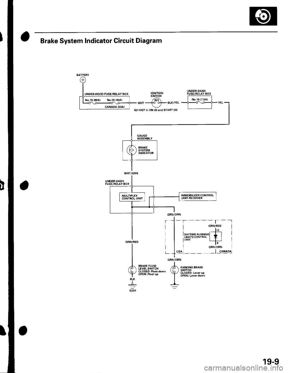
GRN/ORN
,tk ,o"","o ""o*.(b, 3s1E8,.""",,"
I oPEN,Leve,down
I-=:
I
A
YBtK
+csor
Brake System Indicator Circuit Diagram
UNDER.OASHFUSE/FELAYBOX
EBAK€FLUIDIEVELSwlICH
19-9
Page 623 of 1139
Brakes
Conventional Brake Components ................ 1 9-1
ABS (Anti-lock Brake System) Components
Comoonent Location lndex .............,........................... 19-30
General Troubleshooting Information ....................... 19-31
DTC Troubleshooting Index .............. 19-34
Symptom Troubleshooting Index ...,........................... 19-35
System Description ................. ........... 19-36
Circuit Diagram ......... 19-42
DTC Troubleshooting ............... .......... 19-45
ABS Indicator CircuitTroubleshooting ...................... 19-52
Brake System Indicator Circuit
Troubleshooting ...................... ....... 19-55
ABS Modulator-Control Unit Removal and
lnstallation ............. 19-57
Wheel Sensor Insoection ................... 19-59
Wheel Sensor Reolacement .............. 19-59
Page 626 of 1139
ABS Components
General Troubleshooting Information (cont'd)
How to Troubleshoot ABS DTCs
The troubleshooting flowchart procedures assume that
the cause of the oroblem is still Dresent and the ABS
indicator is still on. Following the flowchart when the
ABS indicator does not come on can result in incorrect
diagnosis.
The connector illustrations show the female terminal
connectors with a single outline and the male terminal
connectors with a double outline.
1. Ouestion the customer about the conditions when
the problem occured, and try to reproduce the
same conditions for troubleshooting. Find out
when the ABS indicator came on, such as during
ABS control, after ABS control, when the vehicle
was at a certain speed, etc.
2. When the ABS indicator does not come on during
the test-drive, but troubleshooting is done based on
the DTC, check for loose connectors. poor terminal
contact, etc., before you start troubleshooting.
3. After troubleshooting, clear the DTC,disconnect the
Honda PGM Tester. and test-drive the vehicle.
Make sure the ABS indicator does not come on.
How to Retrieve ABS DTCs
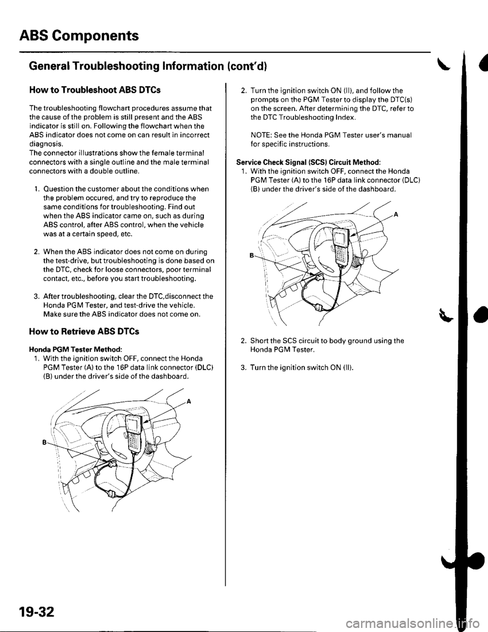
Honda PGM Tester Method:
1, Wjth the ignition switch OFF, connect the Honda
PGM Tester (A) to the 16P data link connector (DLC)
(B) under the driver's side of the dashboard.
19-32
2. Turn the ignition switch ON (ll), and follow the
prompts on the PGM Tester to display the DTC{S)
on the screen. After determining the DTC, refer to
the DTC Troubleshooting Index.
NOTE: See the Honda PGM Tester user's manual
for specific instructions.
Service Check Signal (SCS) Circuit Method:
1. With the ignition switch OFF, connect the Honda
PGM Tester (A) to the 16P data link connector (DLC)
(BI under the driver's side of the dashboard.
2. Short the SCS circuit to body ground using the
Honda PGM Tester.
3. Turn the ignition switch ON (ll).
Page 627 of 1139
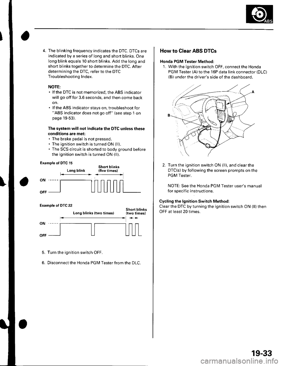
4. The blinking frequency indicates the DTC. DTCS are
indicated by a series of long and short blinks. One
long blink equals 10 shon blinks. Add the long and
short blinks together to determine the DTC. After
determining the DTC, refer to the DTC
Troubleshooting Index.
NOTE:. lf the DTC is not memorized, the ABS indicator
will go off for 3.6 seconds, and then come back
on.. lf the ABS indicatorstays on, troubleshootfor"ABS indicator does not go off" (see step 1 onpage 19-53).
Th€ system will not indicate the DTC unless these
conditions are met:. The brake pedal is not pressed.. The ignition switch is turned ON {ll).. The SCS circuit is shorted to body ground before
the ignition switch is turned ON (ll).
Example ot DTC 15
Long blinkShort blinks{five timesl
Examole of DTC 22
Long blinks (two times)
Turn the ignition swltch OFF,
Disconnect the Honda PG M Tester from the DLC.
5.
How to Clear ABS DTCs
Honda PGM Tester Method:
1. With the ignition switch OFF, connect the Honda
PGM Tester (A)to the l6Pdata link connector (DLC)
{B} under the driver's side of the dashboard.
Turn the ignition switch ON (ll), and clearthe
DTC(s) by following the screen prompts on the
PGM Tester.
NOTE: See the Honda PG l\4 Tester user's manual
for sDeclf ic instructions.
Cycling the lgnition Switch Method:
Clear the DTC by turning the ignition switch ON (ll) then
OFF at least 20 times.
19-33
Page 629 of 1139
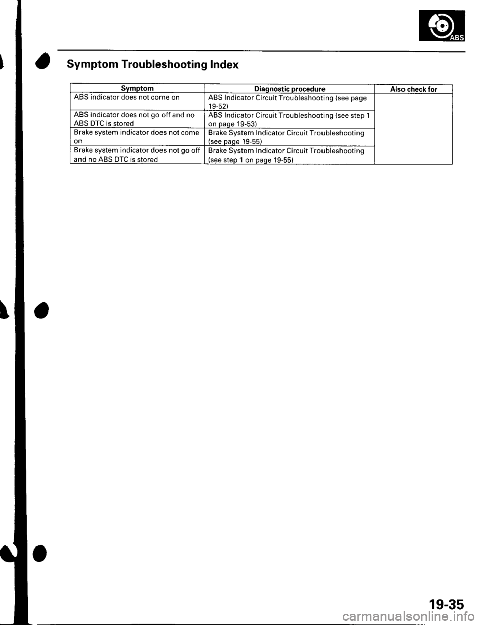
Symptom Troubleshootin g Index
SymptomDiagnostic procedureAlso check forABS indicator does nol come onABS Indicator Circuit Troubleshooting (see page
19-52)
ABS indicator does not go off and no
ABS DTC is stored
ABS Indicator Circuit Troubleshooting {see step 1
on Daqe 19-53)
Brake system indicator does nol come
on
Brake System lndicator Circuit Troubleshooting(see paqe 19-55)
Brake system indicator does not go off
and no ABS DTC is stored
Brake System Indicator Circuit Troubleshooting(see steo 1 on Daqe 19-55)
19-35
Page 633 of 1139
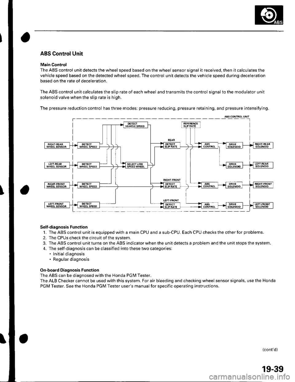
ABS Control Unit
Main Control
The ABS control unit detects the wheel speed based on the wheel sensor signal it received, then it calculates the
vehicle speed based on the detected wheel speed. The control unit detects the vehicle speed during deceleration
based on the rate of deceleration.
The ABS control unit calculates the slip rate of each wheel and transmits the control signal to the modulator unit
solenoid valve when the slip rate is high.
The pressure reduction control has three modes: pressure reducing, pressure retaining, and pressure intensifying.
Self-diagnosis Function
1. TheABScontrol unitisequippedwithamainCPUandasub-CPU.EachCPUcheckstheotherforproblems.
2. The CPUS check the circuit of the system.
3. TheABScontrol unitturns ontheABS ind icator when the unitdetectsa problem andthe unit stops th e system.
4. The self-diagnosis can be classified into these two categories:. lnitial diagnosis. Regular diagnosis
On-board Diagnosis Function
The ABS can be diagnosed with the Honda PGM Tester.
The ALB Checker cannot be used with this system. For air bleeding and checking wheel sensor signals. use the Honda
PGM Tester. See the Honda PGM Tester user's manual for specific operating instructions.
(cont'd)
T---
19-39
Page 634 of 1139
ABS Components
System Description (cont'd)
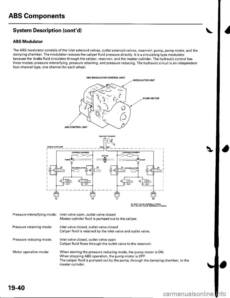
ABS Modulator
The ABS modulator consists of the inlet solenoid valves, outlet solenoid valves, reservoir, pump, pump motor, and the
damping chamber. The modulator reduces the caliper fluid pressure directly. lt is a circulating-type modulator
becausethe brakefluidcirculatesthroughthecaliper,reservoir,andthemastercylinder.Thehydrauliccontrol has
three modes: pressure intensifying, pressure retaining, and pressure reducing. The hydraulic circuit is an independent
four-channeltype, one channel for each wheel.
Pressure intensifying mode: Inletvalve open, outlel valve closed
Master cylinder fluid is pumped out to the caliper.
Pressure retaining mode: lnlet valve closed, outlet valve closed
Caliper fluid is retained by the inlet valve and outlet valve.
Pressure reducing mode: Inlet valve closed, outlet valve open
Caliper fluid flows through the outlet valve to the reservoir.
lvlotor operation mode: When starting the pressure reducing mode, the pump motor is ON.
When stopping ABS operation, the pump motor is OFF.
The caliper fluid is pumped out by the pump, through the damping chamber, to the
master cvlinder.
19-40
Page 636 of 1139
ABS Gomponents
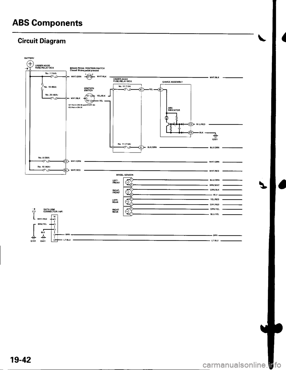
Circuit Diagram
L "*'*" lJ I5l
r**'t?lI r+l
I ^ lo+-sN
Gu csl LqF**,
"'-----
G50l
19-42
Page 638 of 1139
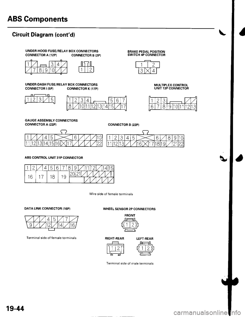
ABS Components
q,
CONNECTOR A {12P)BRAKE PEDAL POSITIONSWITCH 4P CONNECTOR
Circuit Diagram (cont'd)
UNDER-HOOD FUSE/RELAY BOX CONNECTORSCONNECTOR A {12P) CONNECTOR B {2P}
UNDER.DASH FUSE/RELAY BOX CONNECTORSCONNECTOR I {5P)CONNECTOR K I17P)MULTIPLEX CONTROLUNIT 13P CONNECTOR
CONNECTOR B I22PI
1l2l3l,/15
GAUGE ASSEMBLY CONNECTORS
CONNECTOR A I22P)
WHEEL SENSOR 2P CONNECTORS
FRONT
J --T:-l Ltqtt/)l'l L_.:-:J r\-r-----Tr'e:l
RIGHT.REAR LEFT-REAR
tslTt?t /J 1T-1\I tL | rlziJ
Terminal side of male lerminals
ABS CONTROL UNIT 3IP CONNECTOR
OATA LINK CONNECTOR {16P)
Terminal side of female terminals
Wire side of female terminals
1234567
810111213141511
123,/ ,/
67891011n213
1245678I11121415
161118192021/1,/1,/vl,/l
/t,/t/t,/t/
19-44
Page 639 of 1139
\
DTC Troubleshooting
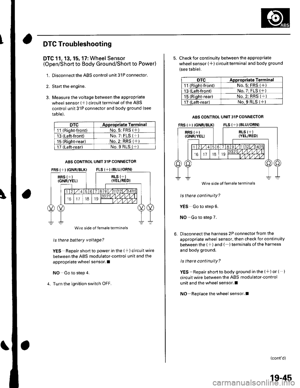
DTC 11, 13, 15, 17: Wheel Sensor
(Open/Short to Body Ground/Short to Power)
1. Disconnect the ABS control unit 31P connector.
2. Sta rt the engine.
3. Measure the voltage between the appropriate
wheel sensor (*)circuitterminal of theABS
control unit 31P connector and body ground (see
table).
DTCADpropriate Terminal
11 (Rioht-front)No.5: FRS (t)
13 (Left-front)No, 7: FLS (*)
15 {Riqht-rear}No. 2: RRS (*)
17 (Left-rear)No.9 RtS (f )
ABS CONTROL UNIT 31P CONNECTOR
FRS {+IIGNR/BLK} FLS I+I (BLU
RRS {+)(GNR/YEL)
Wire side of female terminals
ls thete battery voltage?
YES Repair short to power in the (+) circuit wire
between the ABS modulator-control unit and the
appropriate wheel sensor. I
NO Go to step 4.
4. Turn the ignition switch OFF.
5. Check for continuity between the appropriate
wheel sensor (+ ) circuit terminal and body ground
{see table).
DTCAppropriate Terminal
11 (Riqht-front)No. 5: FRS (+)
13 (Left-front)No. 7: FLS (*)
15 (Rioht-rear)No.2: RRS (*)
17 (Left-rear)No.9 RLS (+l
ABS CONTROL UNIT 31P CONNECTOR
Wire side
ls there continuity?
YES Go to step 6.
NO-Go to step 7.
Disconnect the harness 2P connector from the
appropriate wheel sensor, then check for continuity
between the 1+)and ( )terminals ofthe harness
and body ground.
ls there continuity?
YES-Repair shortto body ground in the (+)or { )
circuit wire between the ABS modulator-control
unit and the wheel sensor.l
NO Repiace the wheel sensor.l
(cont'd)
Wire side of female terminals
19-45