dtc HONDA CIVIC 2003 7.G Workshop Manual
[x] Cancel search | Manufacturer: HONDA, Model Year: 2003, Model line: CIVIC, Model: HONDA CIVIC 2003 7.GPages: 1139, PDF Size: 28.19 MB
Page 787 of 1139
Heating and Air Conditioning
DTC Troubleshooting
DTC 7: An Open in the Air Mix Control Motor
Circuit
1. Test the air mix control motor {see page 2'l-341.
ls the air mix control motor OK?
YES-Go to step 2.
NO-Replace the air mix control motor.l
2. Disconnect the air mix control motor 5P connector.
3. Disconnect heater control panel connectors A {14P)
and B (22P).
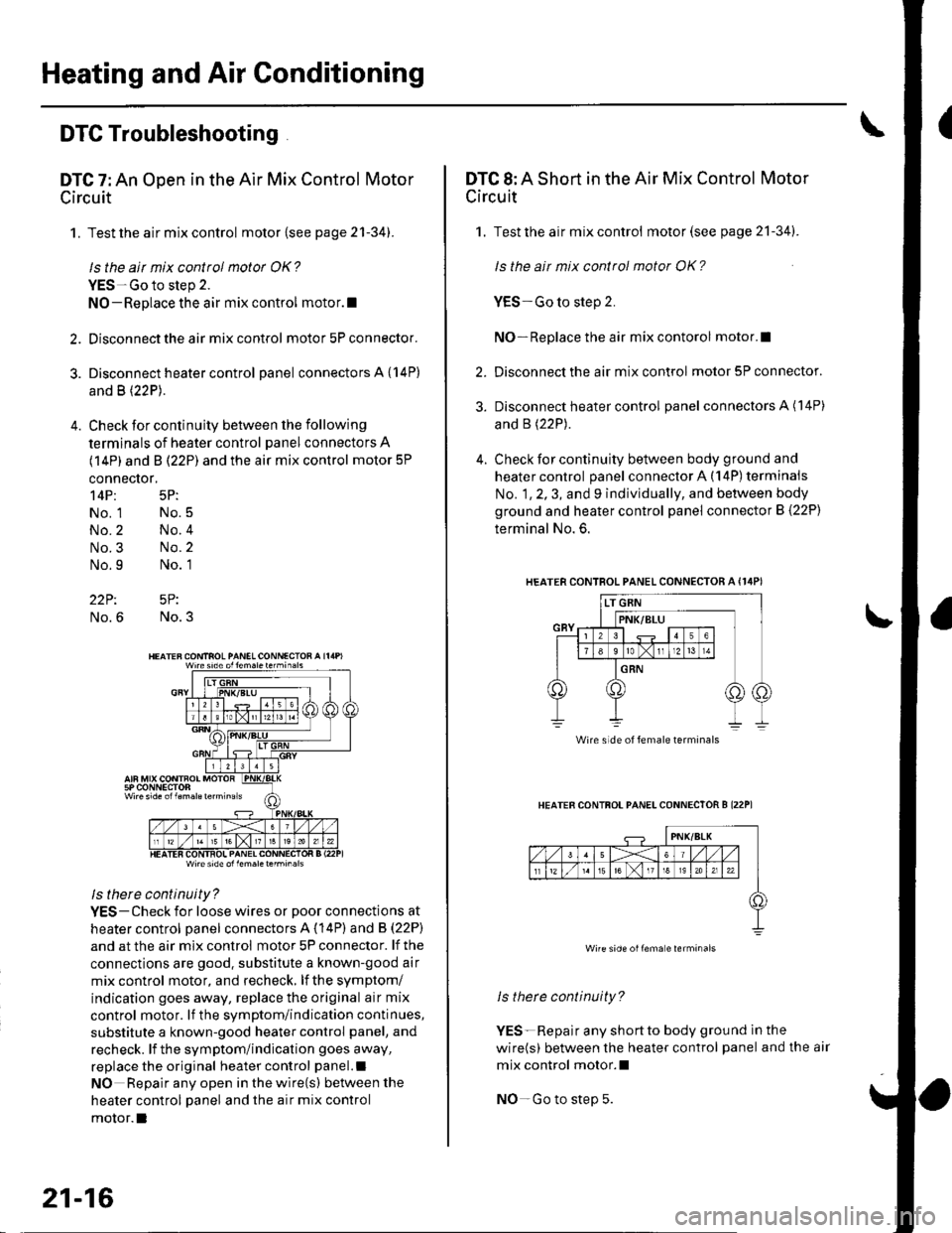
4. Check for continuity between the following
terminals of heater control panel connectors A
(14P) and B (22P) and the air mix control motor 5P
connector,
14P: 5P:
No. 1 No.5
No.2 No.4
No.3 No.2
No.9 No. 1
22P: 5P:
No.6 No.3
Wire side ol lem.letehi.6ls
ls there continuity?
YES-Check for loose wires or poor connections at
heater control oanel connectors A (14P) and B (22P)
and at the air mix control motor 5P connector. lf the
connections are good. substitute a known-good air
mix control motor, and recheck, lf the symptom/
indication goes away, replace the original air mix
control motor. lf the symptom/indication continues,
substitute a known-good heater control panel, and
recheck. lf the symptom/indication goes away,
replace the original heater control panel.l
NO Repair any open inthewire(s) ketweenthe
heater control panel and the air mix control
motor.l
21-16
DTC 8: A Short in the Air Mix Control Motor
Circuit
1. Test the air mix control motor(see page 21-341.
ls the ait mix control motor OK?
YES-Go to step 2.
NO-Replace the air mix contorol motor.I
2. Disconnect the air mix control motor 5P connector.
3. Disconnect heater control panel connectors A (14P)
and B (22P).
4. Check for continuity between body ground and
heater control panel connector A (14P) terminals
No. 1, 2, 3, and 9 individually, and between body
ground and heater control panel connector B (22P)
terminal No. 6.
HEATERCONTROL PANEL CONNECTOR A {I4PI
HEATER CONTFOL PANELCONNECTOR B I22P1
ls therc continuity?
YES-Repair any shortto body ground ln the
wire(s) between the heater control panel and the air
mix control motor.l
NO-Go to step 5.
Wire side of female terminals
Wire side oilema e lerminals
Page 788 of 1139
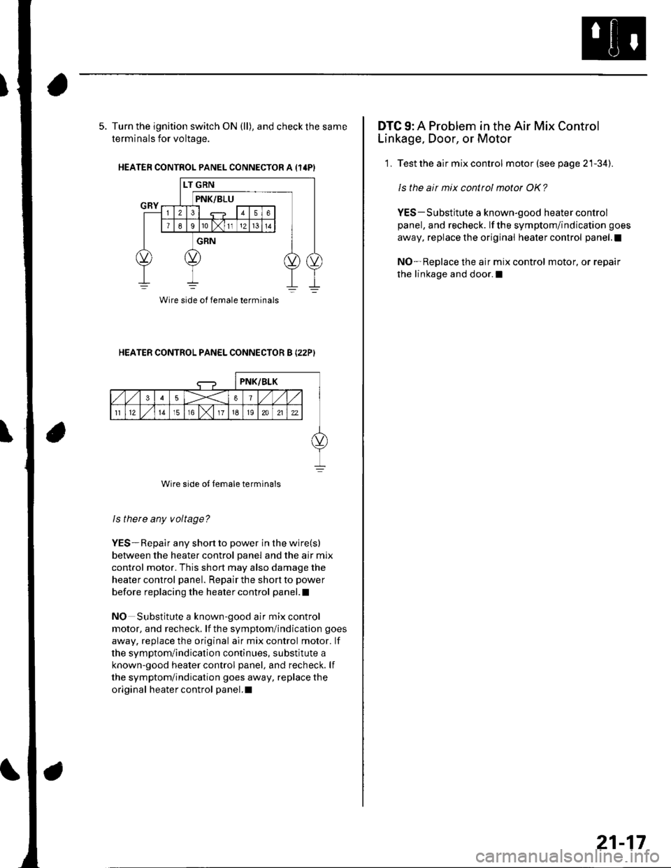
5. Turn the ignition switch ON (ll), and check the same
terminals for voltage.
HEATER CONTROL PANEL CONNECTOR A {14PI
HEATER CONTROL PANEL CONNECTOR B I22PI
Wire side of female terminals
ls there any voltage?
YES-Repair any short to power in the wire(s)
between the heater control panel and the air mix
control motor. This short may also damage the
heater control panel. Repair the short to power
before replacing the heater control panel.l
NO Substitute a known-good air mix control
motor, and recheck. lf the symptom/indication goes
away, replace the original air mix control motor. lf
the symptom/indication continues, substitute a
known-good heater control panel, and recheck. lf
the symptom/indication goes away, replace the
original heater control panel.I
Wire side of female terminals
DTC 9: A Problem in the Air Mix Control
Linkage, Door, or Motor
1, Test the air mix control motor (see page 21-34).
ls the air mix control motor OK?
YES-Substitute a known-good heater control
panel, and recheck. lf the symptom/indication goes
away, replace the original heater control panel.l
NO-Replace the air mix control motor, or repair
the linkage and door.l
21-17
Page 789 of 1139
Heating and Air Conditioning
DTC Troubleshooting.(cont'd)
DTC 10: An Open or Short in the Mode
Control Motor Circuit
1. Test the mode control motor (see page 21-35).
ls the mode cottol motor OK?
YES Go to step 2.
NO Replace the mode control motor.I
Disconnect the mode control motor 10P connector.
Disconnect heater control panel connectors A (14P)
and B \22P1.
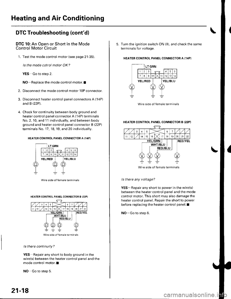
Check for continuity between body ground and
heater control panel connector A (14P) terminals
No. 2, 10, and 11 individually, and between body
ground and heater control panel connector B (22P)
terminals No. '17, 18, 19, and 20 individually.
HEATER CONTROL PANEL CONNECTOR A {14PI
2.
3.
Wire side ol lemale terminals
ls there continuity?
YES Repair any shortto body ground in the
wire(s) between the heater control panel and the
mode control motor.l
NO Go to step 5.
HEATER CONTROL PANELCONNECTOR B {22P)
Wire side of femaLe lerminals
21-18
5. Turn the ignition switch ON (ll), and check the same
terminals for voltage.
HEATEB CONTROL PANEL CONNECTOR A {14P)
Wire side of female terminal
HEATER CONTROL PANEL CONNECTOR B {22PI
35X6
tl1215T61118t92A2122
RED/YELWHT
Wire side of female terminals
ls there any voltage?
YES-. Repair any short to power in the wire(s)
between the heater control panel and the mode
control motor. This short may also damage the
heater control panel. Repair the short to power
before replacing the heater control panel.l
NO- Go to step 6.
Page 790 of 1139
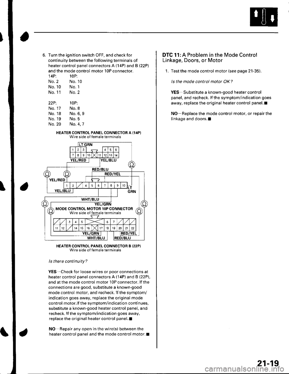
Turn the ignition switch OFF, and check for
continuity between the following terminals of
heater control panel connectors A (14P) and B (22P)
and the mode control motor 10P connector.
14P: 10P:
No. 2 No. '10
No. 10 No, 1
No. 11 No.2
22P: 10P:
No. 17 No.8
No. 18 No.6,9
No. 19 No.5
No. 20 No. 4,7
HEATER CONTROL PANEL CONNECTOR A (14PIWire side of lemale terminals
HEATER CONTROL PANEL CONNECTOR B {22PIWire side of female terminals
ls there continuity?
YES-Check for loose wires or poor connections at
heater control panel connectors A (14P) and B (22P),
and at the mode control motor 10P connector. lf the
connections are good, substitute a known-good
mode control motor, and recheck. lf the symptom/
indication goes away. replace the original mode
control motor.lf the symptom/indication continues,
substitute a known-good heater control panel, and
recheck. lf the symptom/indication goes away,
replace the original heater control panel.l
NO Repair any open in the wire(s) between the
heater control Danel and the mode control motor.l
MODE CONTROL MOTOR lOP CONNECTORWire side of female terminals
DTC 11: A Problem in the Mode Control
Linkage, Doors, or Motor
1. Testthe mode control motor (see page 21-35).
ls the mode control motor OK?
YES Substitute a known-good heater control
panel, and recheck. lf the symptom/indication goes
away, replace the original heater control panel.l
NO Replace the mode control motor, or repair the
linkage and doors.l
21-19
Page 791 of 1139
Heating and Air Gonditioning
DTC Troubleshooting {cont'd)
DTC 12: A Problem in the Blower Motor
Circuit
'1. Check the No. 12 (40A)fuse inthe under-hood
fuse/relay box, and the No. 14 (10A) fuse in the
under-dash f use/relay box.
Are the tuses OK?
YES-Go to step 2.
NO Replace the fuse(s), and recheck.l
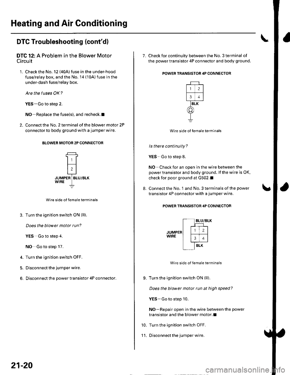
2. Connect the No. 2 terminal of the blower motor 2P
connector to body ground with a jumper wire.
BLOWER MOTOB 2P CONNECTOR
JUMPER ] BLU/BLK
Wire side ol female terminals
3. Turn the ignition switch ON (ll).
Does the blowet motor run?
YES Go to step 4,
NO Go to step 17.
4. Turn the ignition switch OFF.
5. Disconnect the jumper wire.
6. Disconnect the power transistor 4P connector.
21-20
8.
7. Check for continuity between the No. 3 terminal of
the power transistor 4P connector and body ground.
POWER TRANSISTOR 4P CONNECTOR
Wire side ol temale terminals
ls there continuity?
YES-Go to step 8.
NO-Check for an open in the wire between the
power transistor and body ground. lf the wire is OK,
check for poor ground at G502.I
Connect the No. 1 and No. 3 terminals of the power
transistor 4P connector with a jumper wire.
POWER TRANSISTOR 4P CONNECTOR
Wire side of female terminals
Turn the ignition switch ON (ll).
Does the blower motor tun at high speed?
YES-Go to step 10.
NO-Repair open in the wire between the power
transistor and the blower motor.l
Turn the ignition switch OFF.
Disconnect lhe jumper wire.
9.
10.
11.
2
34
BLK
o
Page 793 of 1139
Heating and Air Conditioning
DTC Troubleshooting lcont'd)
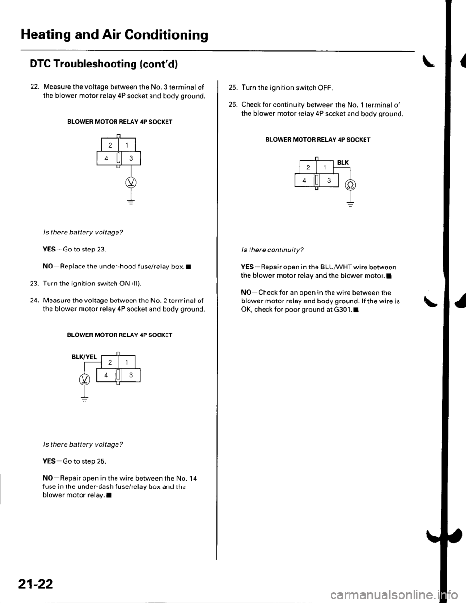
22. Measure the voltage between the No. 3 terminal of
the blower motor relay 4P socket and body ground.
BLOWER MOTOR RELAY 4P SOCKET
21
43
23.
ls there battety voltage?
YES-Go to step 23.
NO Replace the under-hood fuse/relay box.t
Turn the ignition switch ON {ll).
Measure the voltage between the No. 2 terminal of
the blower motor relay 4P socket and body ground,
BLOWER MOTOR RELAY 4P SOCKET
ls there battery voltage?
YES-Go to step 25.
NO Repair open in the wire between the No. 14
fuse in the under-dash fuse/relay box and the
blower motor relay.I
21-22
25.
26.
Turn the ignition switch OFF,
Check for continuity between the No. 1 terminal of
the blower motor relay 4P socket and body ground.
BLOWER MOTOR RELAY 4P SOCKET
ls there continuity?
YES-Repair open in the BLUIr'/HT wire between
the blower motor relay and the blower motor.l
NO Check for an open in the wire between the
blower motor relay and body ground. lf the wire is
OK, check for poor ground at G301.1\
Page 794 of 1139
DTC 14: An Open in the Evaporator
Temperature Sensor Circuit
1. Remove the evaporator temperature sensor (see
page 21-37).
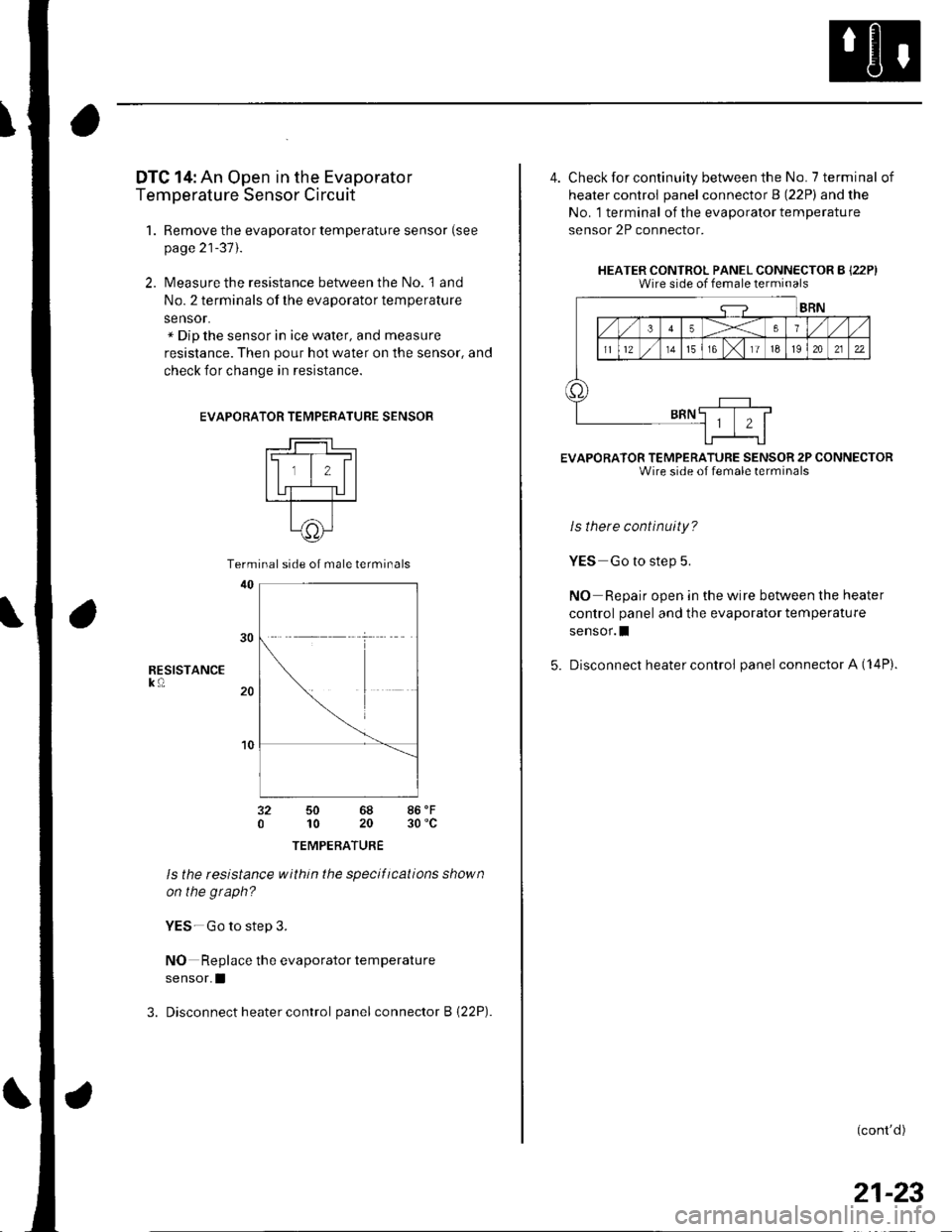
2. Measure the resistance between the No. l and
No. 2 terminals of the evaporator temperature
sensor.x Dip the sensor in ice water, and measure
resistance. Then pour hot water on the sensor, and
check for change in resistance.
EVAPORA
RESISTANCEk0
TOR TEMPERATURE SENSOR
t-lll#l
ll,l,llI UT-TU I---r---T--
t^11c))-l\9/
50 6810 20
TEMPERATURE
ls the tesistance within the specifications shown
on the graph?
YES-Go to step 3.
NO Replace the evaporator temperature
sensor.I
3. Disconnect heater control panel connector B {22P).
86'F30 'c
Terminal side of male terminals
4. Check for continuity between the No. 7 terminal of
heater control panel connector B (22P) and the
No. 1 terminal of the evaporalor temperature
sensor 2P connector.
HEATER CONTROL PANEL CONNECTOR B {22P)Wire side of female terminals
EVAPORATOR TEMPERATURE SENSOR 2P CONNECTORWire side of female terminals
ls there continuity?
YES Go to step 5.
NO Repair open in the wire between the heater
control panel and the evaporator temperature
sensor.I
5. Disconnect heater control panel connector A (14P).
(cont'd)
21-23
Page 795 of 1139
Heating and Air Gonditioning
\
DTC Troubleshooting {cont'd)
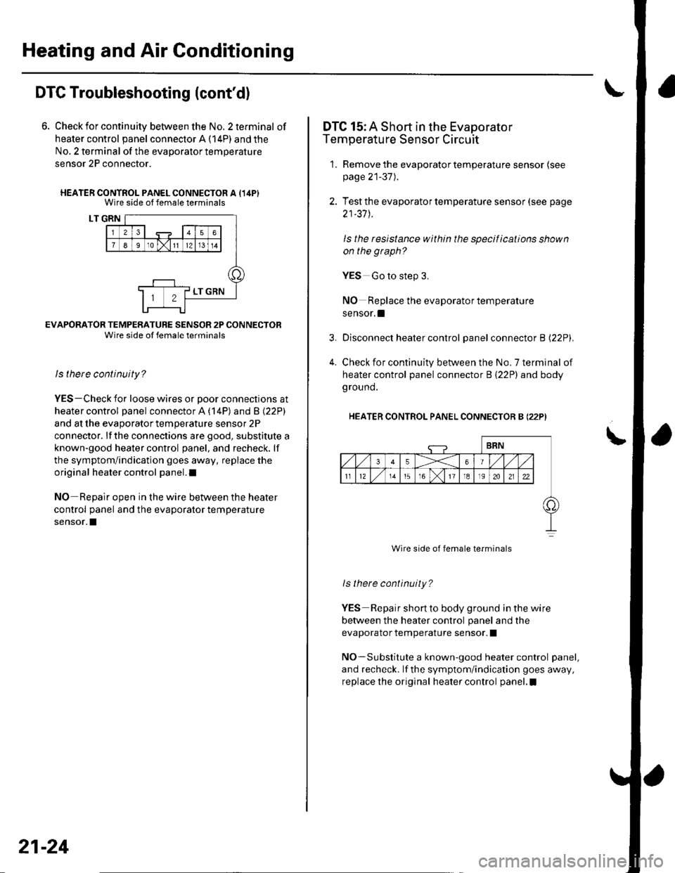
6. Check for continuity between the No. 2 terminal of
heater control panel connector A (14P) and the
No, 2 terminal of the evaporalor temperature
sensor 2P connector.
HEATER CONTROL PANEL CONNECTOR A {14PIWire side of female terminals
LT GRN
EVAFORATOR TEMPERATURE SENSOR 2P CONNECTORWire side of female terminals
ls there continuity?
YES-Check for loose wires or Door connections at
heater control panel connector A ('l4P) and B l22Pl
and at the evaporator temperature sensor 2P
connector. lf the connections are good, substitute a
known-good heater control panel, and recheck. lf
the symptom/indication goes away, replace the
original heater control panel.l
NO Reoair ooen in the wire between the heater
control panel and the evaporator temperature
sensor.I
21-24
4.
DTC 15: A Short in the Evaporator
Temperature Sensor Circuit
1. Remove the evaporator temperature sensor (see
page 21-37).
2. Test the evaporator temperature sensor (see page
21-37 J.
ls the resistance within the specifications shown
on the graph?
YES Go to step 3.
NO Replace the evaporator temperature
sensor. !
Disconnect heater control panel connector B l22Pl.
Check for continuity between the No. 7 terminal of
heater control panel connector B {22P) and body
ground.
HEATER CONTROL PANEL CONNECTOR B (22P)
Wire side of female terminals
ls there continuity?
YES Repair short to body ground in the wire
betvveen the heater control panel and the
evaporator temperature sensor. I
NO-Substitute a known-good heater control panel,
and recheck. lf the symptom/indication goes away,
replace the original heater control panel.I
Page 893 of 1139
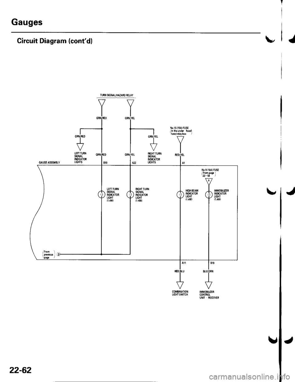
Gauges
\"Circuit Diagram (cont'dl
CoME|NAT|ON tMf,tOBtUZEnLtctlTswtTclt @l TRoLUN|I ftCtIVER
GRNIfiED
I\""'7
VLEFTTUNSIGI'IALII'{DICATORGAUGIASSEi|BLY LTCHTS
\,HIGHSEAM -|. IMMOBITIZERltDtcATon r/: tilucaToB
f,il vll9i,]
22-62
J
Page 895 of 1139
Gauges
2.
3.
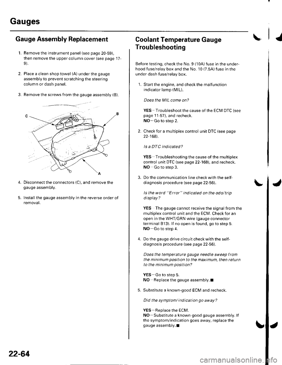
Gauge Assembly Replacement
1.Remove the instrument panel (see page 20-59),
then remove the upper column cover {see page 17-
Place a clean shop towel (A) under the gauge
assembly to prevent scratching the steering
colum n or dash panel.
Remove the screws from the gauge assembly (B).
Disconnect the connectors (C), and remove thegauge assemDry.
Installthe gauge assembly in the reverse order of
removal.
Coolant Temperature Gauge
Troubleshooting
Before testing, check the No. I { 10A) fuse in the under-
hood fuse/relay box and the No. '10 (7.5A) fuse in the
under dash fuse/relay box.
1. Start the engine, and check the malfunction
indicator lamp (MlL).
Does the MIL come on?
YES- Troubleshoot the cause of the ECM DTC (see
page 1 1-57), and recheck.
NO-Go to step 2.
2. Check for a multiplex control unit DTC (see page
22,168).
ls a DTC ind icated?
YES Troubleshooting the cause of the multiplex
control unit DTC {see page 22-168), and recheck.
NO Go to step 3.
3. Do the communication line check with the self-
diagnosis procedure (see page 22-56).
ls the word "Error" indicated on the odo/ttip
d isplay ?
YES The gauge cannot receive the signal from the
multiplex control unit and the ECI\,4. Check for an
open in the WHT/GRN wire (gauge connector
terminal B 13). lf no open is found, go to step 5.
NO Go to step 4.
4. Do the gauge drive circuit check with the self-
diagnosis procedure (see page 22-56).
Does the temperature gauge needle sweep lrom
the minimum position to the maximum, then tetutn
to the minimum position?
YES Go to step 5.
NO Replace the gauge assembly.l
5. Substitute a known-good ECM and recheck.
Did the symptom/ ind ication go away?
YES Replace the ECM.
NO Substitute a known good gauge assembly. lf
the symptom/indication goes away, replace thegauge assembly.l
4.
22-64