Control HONDA CIVIC 2003 7.G Workshop Manual
[x] Cancel search | Manufacturer: HONDA, Model Year: 2003, Model line: CIVIC, Model: HONDA CIVIC 2003 7.GPages: 1139, PDF Size: 28.19 MB
Page 632 of 1139
ABS Gomponents
System Description (cont'd)
Features
When the brake pedal is pressed during driving, the wheels can lock before the vehicle comes to a stop. In such an
event. the maneuverability of the vehicle is reduced if the front wheels are locked, and the stability of the vehicle is
reduced if the rear wheels are locked, creating an extremely unstable condition. The ABS precisely controls the slip
rate of the wheels to ensure maximum grip force from the tires, thereby ensuring the maneuverability and stability of
the vehicle.
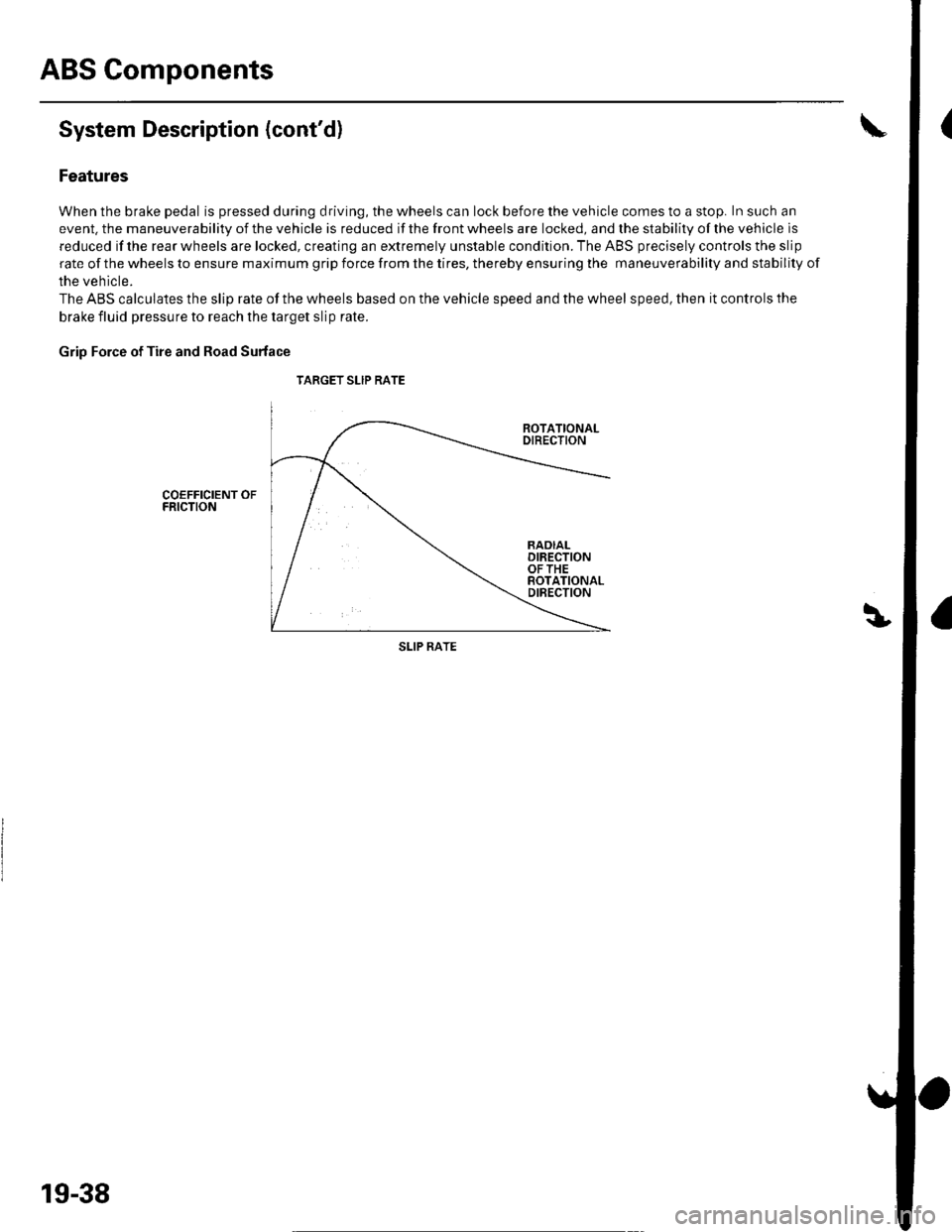
The ABS calculates the slip rate of the wheels based on the vehicle speed and the wheel speed, then it controls the
brake fluid pressure to reach the target slip rate.
Grip Force of Tire and Road Surface
TARGET SLIP RATE
COEFFICIENT OFFRICTION
SLIP RATE
19-38
Page 633 of 1139
ABS Control Unit
Main Control
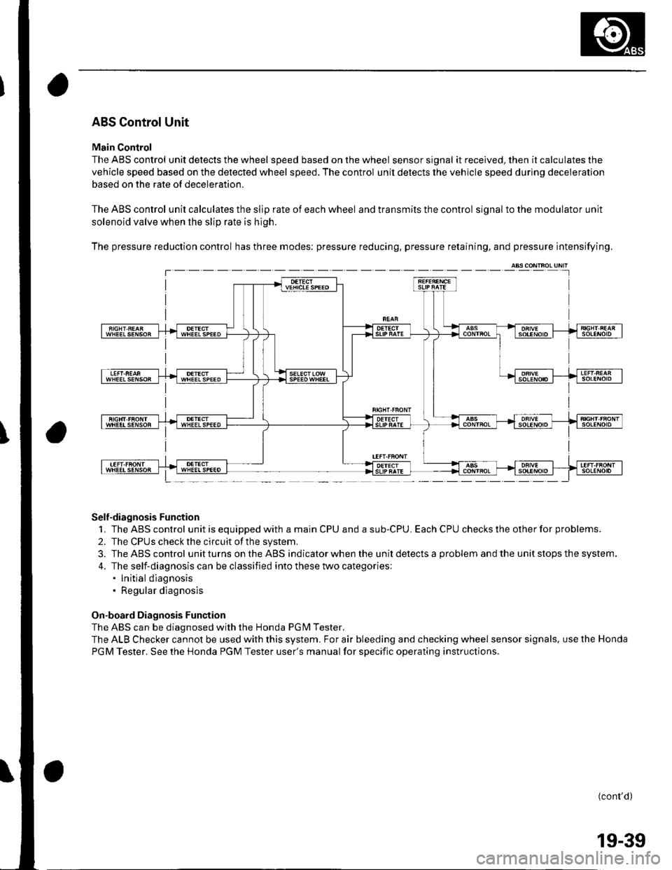
The ABS control unit detects the wheel speed based on the wheel sensor signal it received, then it calculates the
vehicle speed based on the detected wheel speed. The control unit detects the vehicle speed during deceleration
based on the rate of deceleration.
The ABS control unit calculates the slip rate of each wheel and transmits the control signal to the modulator unit
solenoid valve when the slip rate is high.
The pressure reduction control has three modes: pressure reducing, pressure retaining, and pressure intensifying.
Self-diagnosis Function
1. TheABScontrol unitisequippedwithamainCPUandasub-CPU.EachCPUcheckstheotherforproblems.
2. The CPUS check the circuit of the system.
3. TheABScontrol unitturns ontheABS ind icator when the unitdetectsa problem andthe unit stops th e system.
4. The self-diagnosis can be classified into these two categories:. lnitial diagnosis. Regular diagnosis
On-board Diagnosis Function
The ABS can be diagnosed with the Honda PGM Tester.
The ALB Checker cannot be used with this system. For air bleeding and checking wheel sensor signals. use the Honda
PGM Tester. See the Honda PGM Tester user's manual for specific operating instructions.
(cont'd)
T---
19-39
Page 634 of 1139
ABS Components
System Description (cont'd)
ABS Modulator
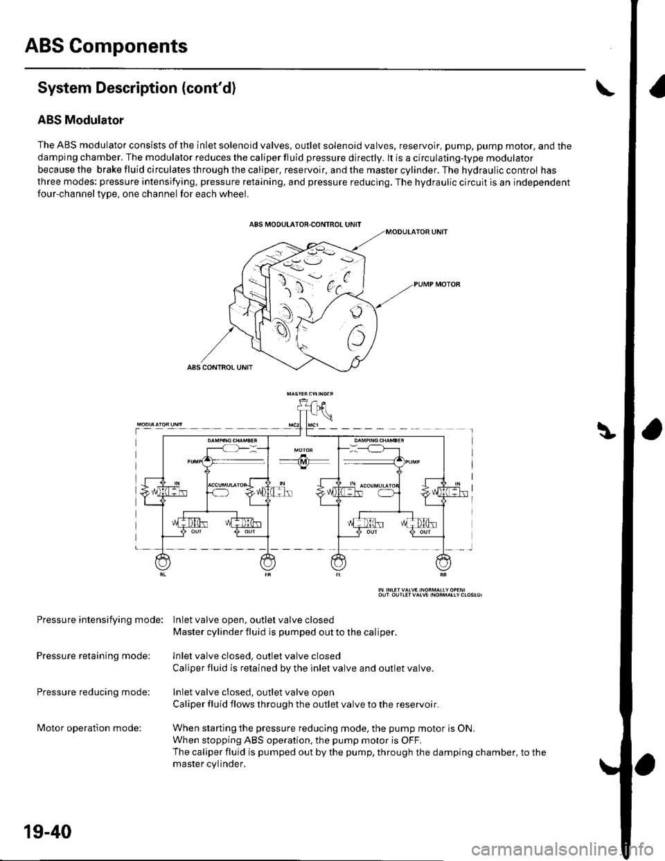
The ABS modulator consists of the inlet solenoid valves, outlet solenoid valves, reservoir, pump, pump motor, and the
damping chamber. The modulator reduces the caliper fluid pressure directly. lt is a circulating-type modulator
becausethe brakefluidcirculatesthroughthecaliper,reservoir,andthemastercylinder.Thehydrauliccontrol has
three modes: pressure intensifying, pressure retaining, and pressure reducing. The hydraulic circuit is an independent
four-channeltype, one channel for each wheel.
Pressure intensifying mode: Inletvalve open, outlel valve closed
Master cylinder fluid is pumped out to the caliper.
Pressure retaining mode: lnlet valve closed, outlet valve closed
Caliper fluid is retained by the inlet valve and outlet valve.
Pressure reducing mode: Inlet valve closed, outlet valve open
Caliper fluid flows through the outlet valve to the reservoir.
lvlotor operation mode: When starting the pressure reducing mode, the pump motor is ON.
When stopping ABS operation, the pump motor is OFF.
The caliper fluid is pumped out by the pump, through the damping chamber, to the
master cvlinder.
19-40
Page 635 of 1139
t
Wheel Sensors
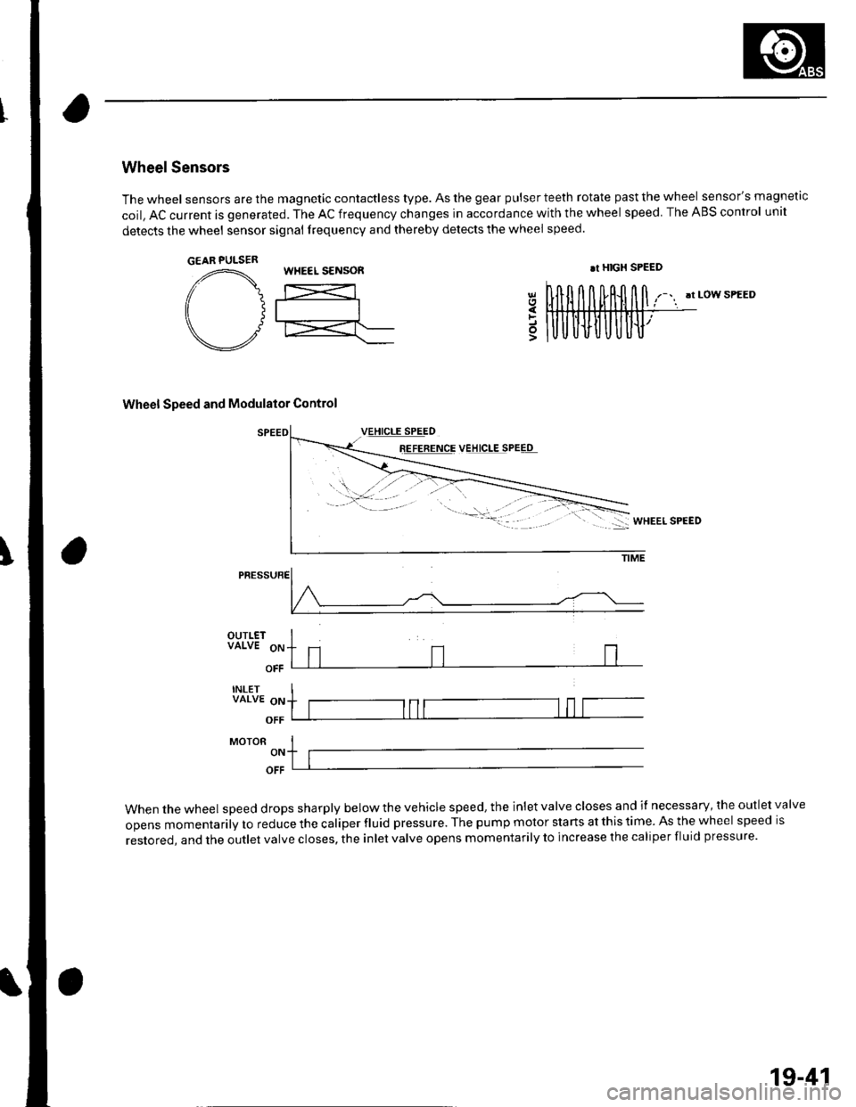
The wheel sensors are the magnetic contactless type. As the gear pulser teeth rotate past the wheel sensor's magnetic
coil, AC current is generated. The AC frequency changes in accordance with the wheel speed. The ABS control unit
detects the wheel sensor signal frequency and thereby detects the wheel speed.
!t LOW SPEED
Wheel Speed and Modulator Control
8E!EEETqE VEJ!q!ESPEEq
5
PRESSURE
OUTLETVALVE 9p
OFF
INLETVALVE oN
OFF
MoroR I-,. ltlOFF
When the wheel speed drops sharply below the vehicle speed, the inlet valve closes and il necessary, the outlet valve
opens momentarily to reduce the caliper fluid pressure. The pump motor starts at this time. As the wheel speed is
restored, and the outlet valve closes, the inlet valve opens momentarily to increase the caliper fluid pressure.
GEAR PULSERWHEEL S€NSOR.r HIGX SPEED
19-41
Page 638 of 1139
ABS Components
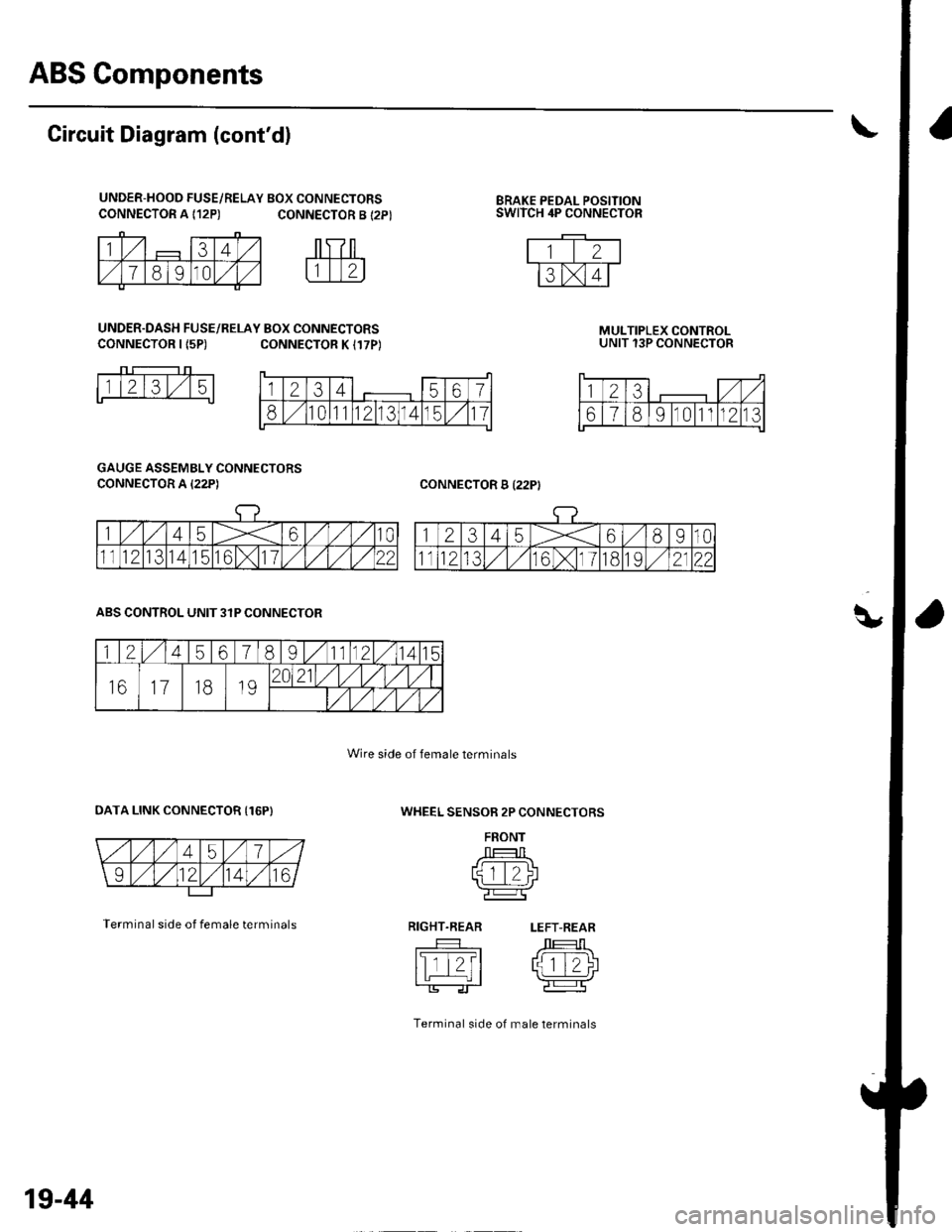
q,
CONNECTOR A {12P)BRAKE PEDAL POSITIONSWITCH 4P CONNECTOR
Circuit Diagram (cont'd)
UNDER-HOOD FUSE/RELAY BOX CONNECTORSCONNECTOR A {12P) CONNECTOR B {2P}
UNDER.DASH FUSE/RELAY BOX CONNECTORSCONNECTOR I {5P)CONNECTOR K I17P)MULTIPLEX CONTROLUNIT 13P CONNECTOR
CONNECTOR B I22PI
1l2l3l,/15
GAUGE ASSEMBLY CONNECTORS
CONNECTOR A I22P)
WHEEL SENSOR 2P CONNECTORS
FRONT
J --T:-l Ltqtt/)l'l L_.:-:J r\-r-----Tr'e:l
RIGHT.REAR LEFT-REAR
tslTt?t /J 1T-1\I tL | rlziJ
Terminal side of male lerminals
ABS CONTROL UNIT 3IP CONNECTOR
OATA LINK CONNECTOR {16P)
Terminal side of female terminals
Wire side of female terminals
1234567
810111213141511
123,/ ,/
67891011n213
1245678I11121415
161118192021/1,/1,/vl,/l
/t,/t/t,/t/
19-44
Page 639 of 1139
\
DTC Troubleshooting
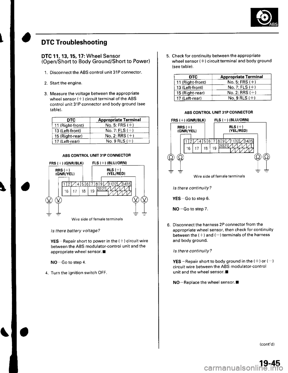
DTC 11, 13, 15, 17: Wheel Sensor
(Open/Short to Body Ground/Short to Power)
1. Disconnect the ABS control unit 31P connector.
2. Sta rt the engine.
3. Measure the voltage between the appropriate
wheel sensor (*)circuitterminal of theABS
control unit 31P connector and body ground (see
table).
DTCADpropriate Terminal
11 (Rioht-front)No.5: FRS (t)
13 (Left-front)No, 7: FLS (*)
15 {Riqht-rear}No. 2: RRS (*)
17 (Left-rear)No.9 RtS (f )
ABS CONTROL UNIT 31P CONNECTOR
FRS {+IIGNR/BLK} FLS I+I (BLU
RRS {+)(GNR/YEL)
Wire side of female terminals
ls thete battery voltage?
YES Repair short to power in the (+) circuit wire
between the ABS modulator-control unit and the
appropriate wheel sensor. I
NO Go to step 4.
4. Turn the ignition switch OFF.
5. Check for continuity between the appropriate
wheel sensor (+ ) circuit terminal and body ground
{see table).
DTCAppropriate Terminal
11 (Riqht-front)No. 5: FRS (+)
13 (Left-front)No. 7: FLS (*)
15 (Rioht-rear)No.2: RRS (*)
17 (Left-rear)No.9 RLS (+l
ABS CONTROL UNIT 31P CONNECTOR
Wire side
ls there continuity?
YES Go to step 6.
NO-Go to step 7.
Disconnect the harness 2P connector from the
appropriate wheel sensor, then check for continuity
between the 1+)and ( )terminals ofthe harness
and body ground.
ls there continuity?
YES-Repair shortto body ground in the (+)or { )
circuit wire between the ABS modulator-control
unit and the wheel sensor.l
NO Repiace the wheel sensor.l
(cont'd)
Wire side of female terminals
19-45
Page 640 of 1139
ABS Components
DTC Troubleshooting (cont'dl
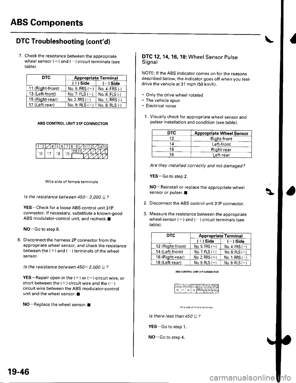
7. Check the resistance between the appropriate
wheel sensor (+) and ( ) circuit terminals {seeta ble).
DTCAppropriate Terminal
l+) Side*lSide
11 {Riqht-front)No.5: FRS (*)No.4:FRS 1-)'13 {Left-front)No. 7: FLS {+iNo.6: FLS (-
15 (Rioht-rear)No. 2: RBS {+)No. 1:RBS (-)
17 (Left-rear)No.9: RLS 1-No.8: BLS (-
ABS CONTROL UNIT 31P CONNECTOR
Wire side of female terminals
Is the rcsistance between 450 2,000 A ?
YES Check for a loose ABS control unit3lP
connector. lf necessary. substitute a known-good
ABS modulator-control unit, and recheck.l
NO Go to step 8.
Disconnect the harness 2P connector from theappropriate wheel sensor, and check the resistance
between the (+) and { )terminalsof thewheel
sensor.
ls the resistance between 450- 2,000 Q ?
YES-Repair open in the (+) or (-) circuit wire, orshort between the (+) circuit wire and the { )circuit wire between the ABS modulator-control
unit and the wheel sensor.l
NO Replace the wheel sensor.l
19-46
DTC12,14, 16, 18: Wheel Sensor Putse
Signal
NOTE: lf the ABS indicator comes on for the reasonsdescribed below, the indicator goes off when you test-drive the vehicle at 31 mph (50 km/nl.
. Only the drive wheel rotated. The vehicle spun. Electrical noise
1. Visually check for appropriate wheel sensorandpulser installation and condition (see table).
DTCAppropriate Wheel Sensor
12Riqht-front
14Left-front
Riqht-rear
18Left-rear
Ate they installed correctly and not damaged?
YES-Go to step 2,
NO Reinstall or replace the appropriate wheelsensor or pulser,I
Disconnect the ABS control unit 31P connector.
Measure the resistance between the appropriate
wheel sensor ( f) and ( ) circuit terminals (see
table).
ls therc less than 450 Q ?
YES Go to step 1.
NO-Go to step 4.
\\|D
2.
3.
DTCAppropriate Terminal
l*) Side) Side
12 {Rioht-front)No.5:FBS (*No.4:FBS
14 (Left-front)No.7;FLS l*No,6:FLS
16 (Riqht.rear)No.2: RRS (*No. 1:BRS
18 (Left-readNo.9: BLS 1-No.8:RLS
Page 641 of 1139
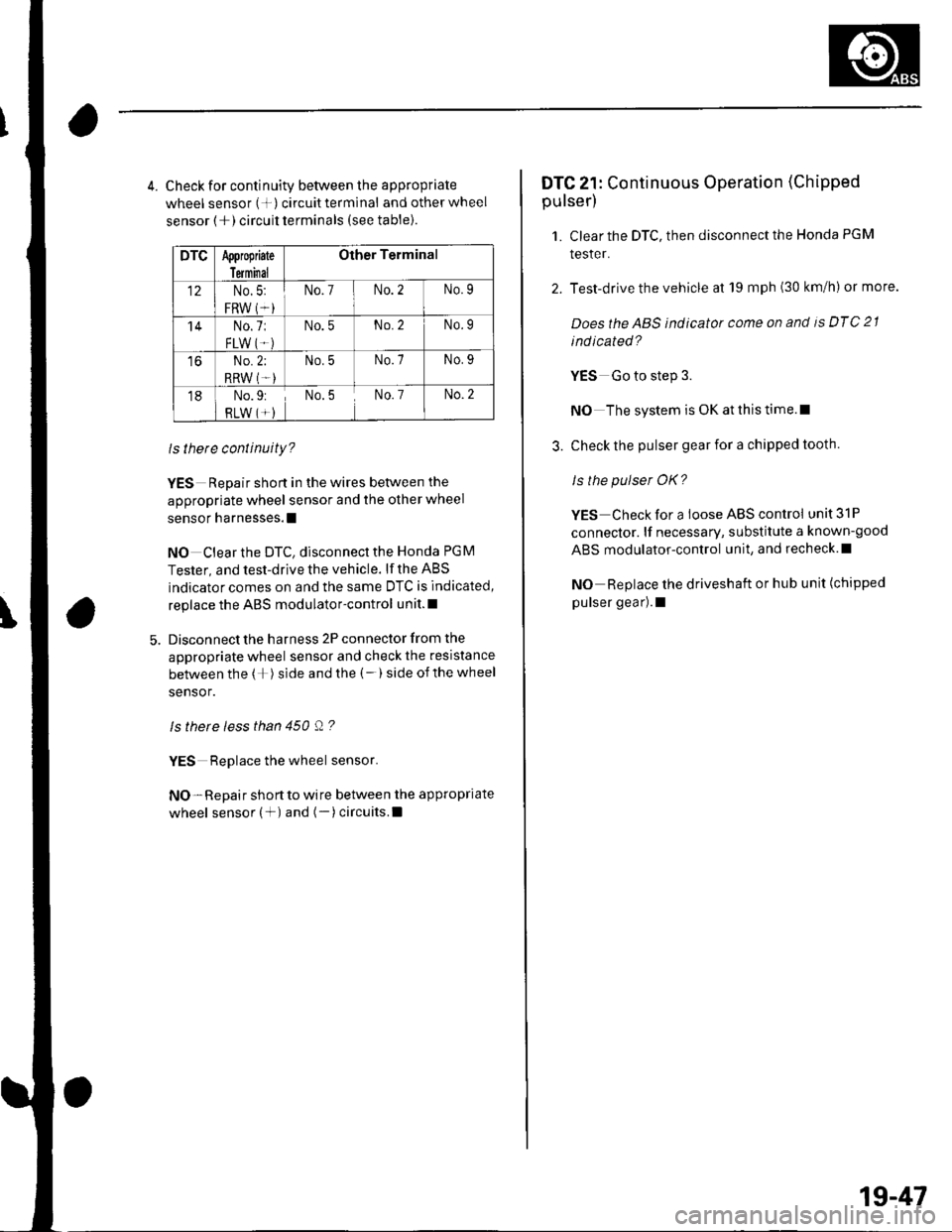
4. Check for continuity between the appropriate
wheel sensor (+) circuittermlnal and otherwheel
sensor (+) circuit terminals (see table).
DTCAppropiate
Terminal
Other Terminal
12No.5:
FRW (*i
No.7No.2No.9
'14No.7:
FLW IT.)
No.5No.2No.9
toNo.2;
RRW (T-)
No.5No.7No.9
18No.9:
RLW (*)No.5No. 7No.2
ls there continuity?
YES Repair short in the wires between the
appropriate wheel sensor and the other wheel
sensor harnesses.l
NO Clear the DTC, disconnect the Honda PGM
Tester, and test-drive the vehicle. lf the ABS
indicator comes on and the same DTC is indicated,
replace the ABS modulator-control unit.l
Disconnect the harness 2P connector from the
appropriate wheel sensor and check the resistance
between the (+) side and the (-) side ofthe wheel
sensor.
ls there less than 450 Q ?
YES Replace the wheel sensor.
NO- Repair short to wire between the appropriate
wheel sensor (+) and (-)circuits.l
DTC 21: Continuous Operation (Chipped
pulser)
1. Clear the DTC, then disconnect the Honda PGM
tesler.
2. Test-drive the vehicle at 19 mph (30 km/h) or more.
Doesthe ABS indicator come on and is DTC 21
ind icated?
YES Go to step 3.
NO The system is OK at this time.l
3. Check the pulser gear for a chipped tooth.
ls the pulser OK?
YES Check for a loose ABS control unit 31P
connector. lf necessary, substitute a known-good
ABS modulator-control unit, and recheck.l
NO Replace the driveshaft or hub unit (chipped
pulser gear).1
1g-47
Page 642 of 1139
ABS Components
DTC Troubleshooting (cont'd)
DTC 31, 32. 33, 34, 35, 36, 37, 38: Solenoid
1. Clear the DTC, then disconnect the Honda PGN4
Tester.
2. Test-drive the vehicle.
Does the ABS ind icator come on and are DT Cs 31,
32, 33, 34, 35, 36, 37, 38 indicated?
YES Replace the ABS modulator-control unit.t
NO The system is OK at this time. t
19-48
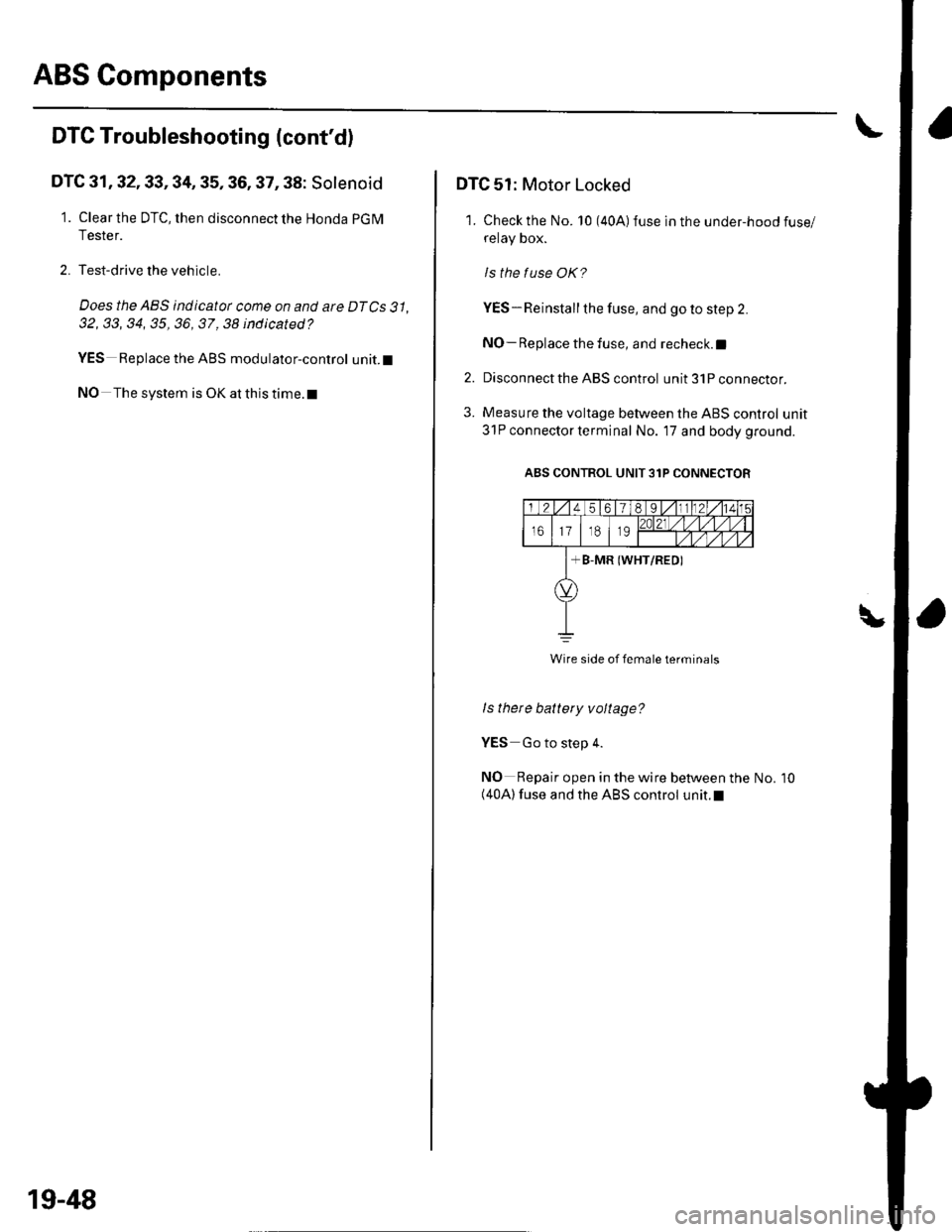
DTC 51: Motor Locked
'1. Check the No. 10 (40A)fuse in the under-hoodfuse/
retay Dox.
ls the tuse OK?
YES-Reinstall the fuse, and go to step 2.
NO- Replace the fuse, and recheck.l
2. Disconnect the ABS control unit 31P connector.
3. Measure the voltage between the ABS control unit
31P connector terminal No. 17 and body ground.
ABS CONTROL UNIT 31P CONNECTOR
I
Wire side of female terminals
ls thete battery voltage?
YES Go to step 4.
NO Repair open in the wire between the(40A) fuse and the ABS control unit.l
No. 10
Page 643 of 1139
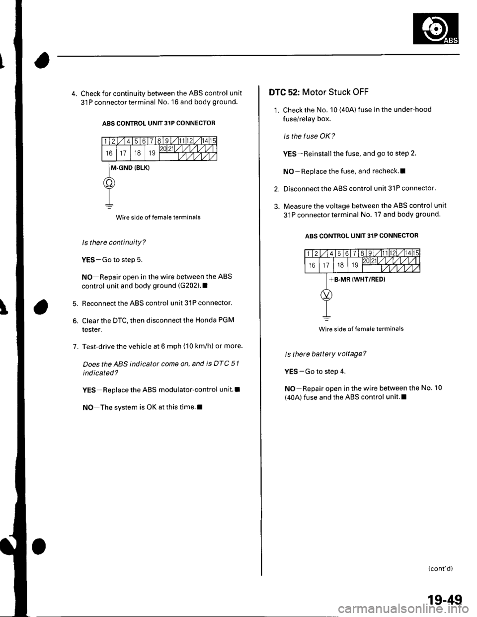
4. Check for continuity between the ABS control unit
31 P connector terminal No. 16 and body grou nd.
ABS CONTROL UNIT 31P CONNECTOR
Wire side of female terminals
ls there continuity?
YES-Go to step 5.
NO Repair open in the wire between the ABS
control unit and body ground (G202).1
Reconnect the ABS control unit 31P connector.
Clear the DTC, then disconnect the Honda PGM
tester.
Test-drive the vehicle at 6 mph (10 km/h) or more.
Doesthe ABS indicator come on, and is DTC 51
indicated?
YES Replace the ABS modulator-control unit.l
NO The system is OK at this time.l
6.
7.
DTG 52: Motor Stuck OFF
1. Check the No. 10(40A) fuse in the under-hood
fuse/relay box.
ls the f use OK?
YES-Reinstall the fuse, and go to step 2.
NO-Replace the fuse, and recheck.l|
Disconnect the ABS control unit 31P connector.
Measure the voltage between the ABS control unit
31P connector terminal No. 17 and body ground
ABS CONTROL UNIT 31P CONNECTOR
2.
3.
ls there battery voltage?
YES-Go to step 4.
NO Repair open in the wire between the
(40A) fuse and the ABS control unit.l
No. 10
(cont'di
Wire side of female terminals
19-49