Control HONDA CIVIC 2003 7.G Workshop Manual
[x] Cancel search | Manufacturer: HONDA, Model Year: 2003, Model line: CIVIC, Model: HONDA CIVIC 2003 7.GPages: 1139, PDF Size: 28.19 MB
Page 696 of 1139
Moonroof
1.
Frame and Drain Tube Replacement
Remove these items:
. Headliner (see page 20-54). Moonroof glass (see page 20-37)
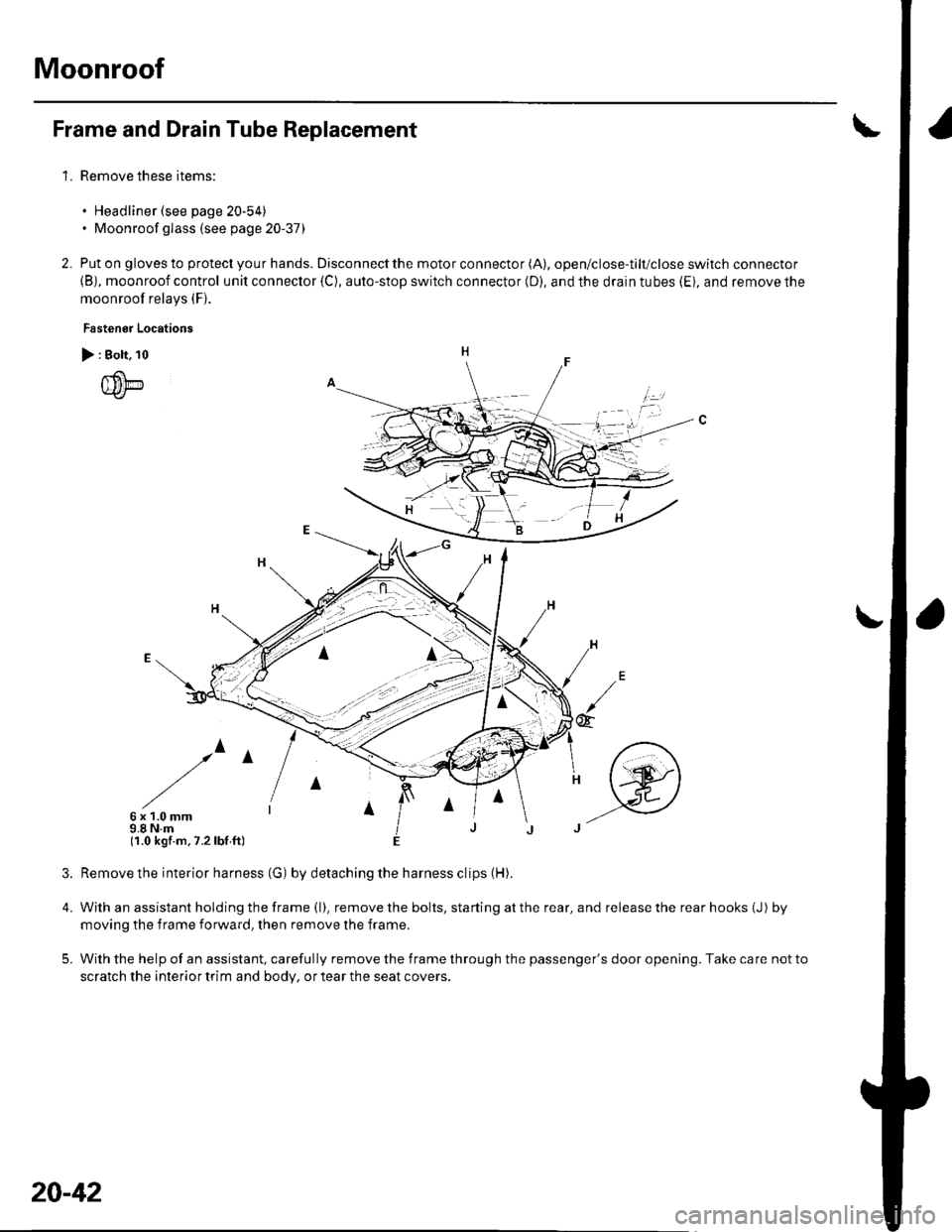
Put on gloves to protect you r hands. Disconnect the motor connector (A), open/close-tilt/close switch connector
{B), moonroof control unit connector {C), auto-stop switch connector (D), and the drain tubes (Ei, and remove the
moonroof relays (F).
Fastenor Locations
> : Bolt, 10
{um
/^
6x1.0mm9.8 N.m(1.0 kgf.m,7.2lbf ft)
4.
5.
2.
irl
@
Remove the interior harness (G) by detaching the harness clips (H).
With an assistant holding the frame (l). remove the bolts, starting at the rear, and release the rear hooks (J) by
moving the f rame forward, then remove the frame.
With the help of an assistant, carefully remove the frame through the passenger's door opening. Take care not to
scratch the interior trim and body, or tear the seat covers.
20-42
Page 716 of 1139
Dashboard
Dashboard Center Panel Removal/lnstallation
NOTE:. Put on gloves to protect your hands.. When prying with a flat-tip screwdriver, wrap it with
protective tape, and apply protective tape around the
related parts, to prevent damage.. Take care not to scratch the dashboard and related
parts.
1. Make sure you have the anti-theft code for the radio,
the write down the frequencies for the preset
buttons.
Remove these items:
. Driver's dashboard lower cover (see page 20-59)
. Passenger's dashboard lower cover (see page
20-63).. Glove box (see page 20-63).. Shift lever trim {see page 20-61).
From the glove box and driver's dashboard Iower
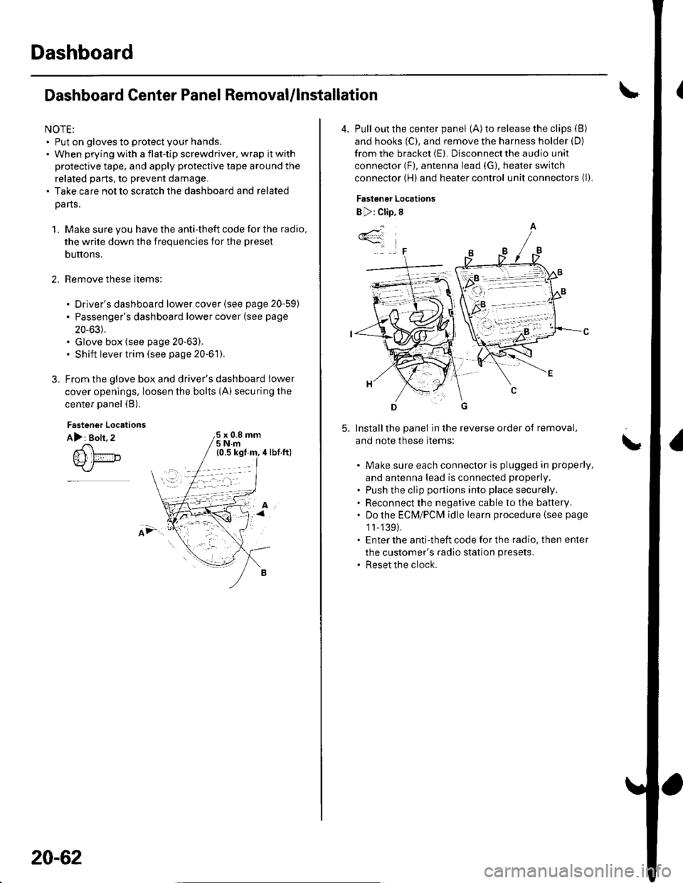
cover openings, loosen the bolts (A) securing the
center panel (B).
2.
Fastener Locations
A): Bolt, 2x 0.8 mm5Nm
;.'
20-62
4. Pull out the center panel (A) to release the clips (B)
and hooks (C), and remove the harness holder (D)
from the bracket (E). Disconnect the audio unit
connector (F), antenna lead (G), heater switch
connector (H) and heater control unit connectors (l).
Fastener Locations
B ): Clip, 8
Installthe panel in the reverse order of removal,
and note these items:
Make sure each connector is plugged in properly,
and antenna lead is connected properly.
Push the clip portions into place securely.
Reconnect the negative cable to the battery.
Do the ECN4/PCt\4 idle learn procedure {see page
1l-139).
Enter the anti-theft code for the radio. then enter
the customer's radio station presets.
Reset the clock.
*4
,F
\
Page 722 of 1139
Dashboard
Dashboard Removal/lnstallation
(cont'd)
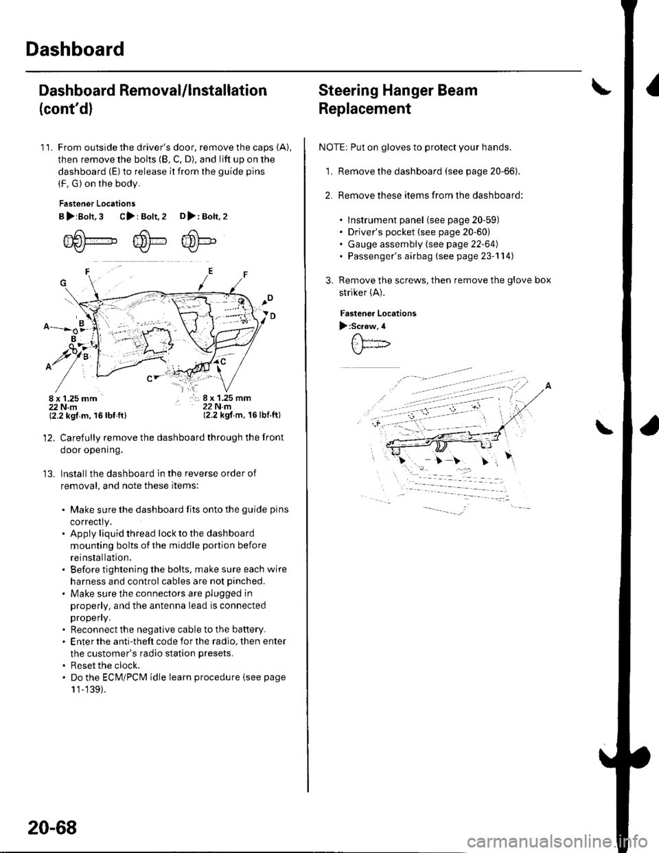
11. From outside the driver's door, remove the caps (A),
then remove the bolts (8, C, D), and lift up on the
dashboard (E) to release it from the guide pins
(F. G) on the body.
Fastener Locations
B>rBolt.3 C>: Bolt,2 D>: Bolt,2
m6[-,,,,",",,-,F6't---'' ffi'!--v{/- Kr* w-
B
$7:
^/761:
/,-,. r:; 8 x 1.25 mm22Nm(2.2 kgf.m, 16lbf.ft)
13.
{2.2 kgf m, 16lbf.ftl
Carefully remove the dashboard through the front
door opening.
lnstall the dashboard in the reverse order of
removal, and note these items:
. Make sure the dashboard fits onto the guide pins
correctly.. Apply liquid thread lock to the dashboard
mounting bolts of the middle portion before
reinstallation.. Before tightening the bolts, make sure each wire
harness and control cables are not pinched.
. Make sure the connectors are plugged in
properly, and the antenna lead is connected
propeny.. Reconnect the negative cable to the battery.. Enter the anti-theft code for the radio, then enter
the customer's radio station presets.
. Reset the clock.. Do the ECM/PCM idle learn procedure isee page
1 '1-139).
20-68
Steering Hanger Beam
Replacement
NOTE: Put on gloves to protect your hands.
1, Remove the dashboard (see page 20-66).
2. Remove these items from the dashboard:
. lnstrument panel (see page 20-59). Driver's pocket (see page 20-60). Gauge assembly (see page 22-64). Passenger's airbag (see page 23-'l 14)
Remove the screws, then remove the glove box
striker (A).
Fastenea Locations
):Screw,4
\
Page 723 of 1139
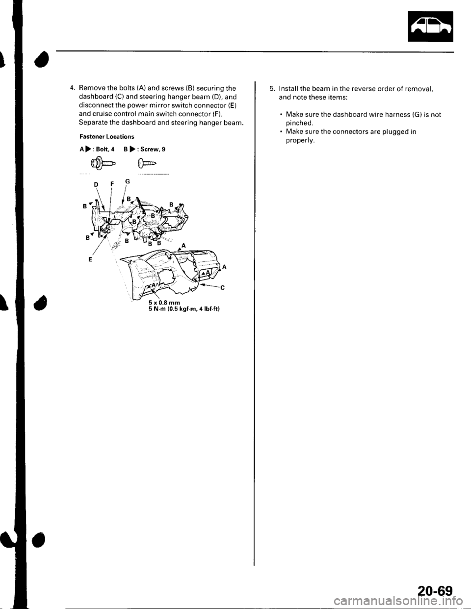
4. Remove the bolts (A) and screws (B) securing the
dashboard (C) and steering hanger beam (D), and
disconnect the power mirror switch connector (E)
and cruise control main switch connector (F).
Separate the dashboard and steering hanger beam.
Faslener Locations
A>rBolt,4 B>:Screw,9
5 N.m {0.5 kgf m,4lbf,ftl
5. Installthe beam in the reverse order of removal,
and note these items:
. N4ake sure the dashboard wire harness (G) is notpinched.
. Make sure the connectors are plugged in
properly.
20-69
Page 731 of 1139
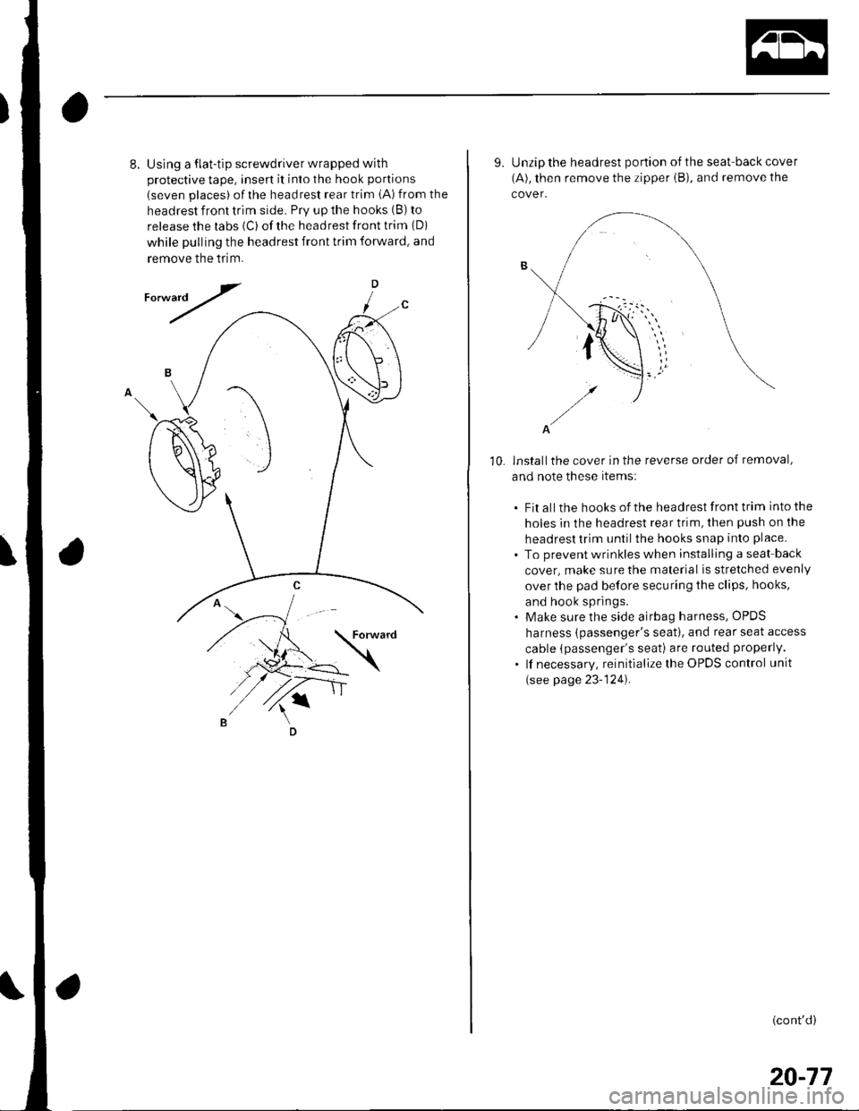
8.Using a flat-tip screwdriver wrapped with
protective tape, insert it into the hook portions
(seven places) ofthe headrest rear trim iA) from the
headrest front trim side. Prv up the hooks (B) to
release the labs (C) of the headrest front trim (Di
while pulling the headrest front trim forward, and
remove the tflm.
D
/
10.
9. Unzip the headrest portion of the seat-back cover
(A), then remove the zipper iB), and remove the
cover.
A
installthe cover in the reverse order of removal,
and note these items:
. Fit all the hooks of the headrest front trim into the
holes in the headrest rear trim, then push on the
headrest trim until the hooks snap into place.
. To prevent wrinkles when installing a seat back
cover, make sure the material is stretched evenly
over the pad before securing the clips, hooks,
and hook springs.. Make sure the side airbag harness, OPDS
harness {passenger's seat). and rear seat access
cable (passenger's seati are routed properly.
. lf necessary, reinitialize the OPDS control unit
(see page 23-124).
(cont'd)
20-77
Page 773 of 1139
21-2
z t-'5
z t-o
z t-o
21-8
21-9
21-10
21-11
21-14
z t- to
HVAC (Heating, Ventilation, and Air Gonditioningl
Heating and Air Conditioning
SpecialTools
Comoonent Location lndex ........
A/C Service Tios and
Precautions
A,/C Refrigerant Oil
ReDlacement
General Troubleshooting
lnformation
DTC Troubleshooting Index .......
Symptom Troubleshooting
1ndex..............
System Description .....................
Circuit Diagram
DTC Troubleshooting ..................
Recirculation Control Motor
CircuitTroubleshooting .......... 21-25
Heater Control Power and Ground
Circuits Troubleshooting ........ 21-27
Condenser Fan Circuit
Troubleshooting ...................... 21-28
Radiator and Condenser Fans
Common Circuit
Troubfeshooting ...................... 21-29
Compressor Clutch Circuit
Troubleshooting ...................... 21-30
A,/C Pressure Switch Circuit
Troubleshooting ...................... 21-32
Air Mix Control Motor
Test and Reolacement ............. 21-34
Mode Control Motor
Test and Replacement ............. 21-35
Recirculation Control Motor
Test and Reolacement ............. 21-36
Evaporator Temperature Sensor
Reolacement and Test ............. 21-31
Power Transistor Test ................. 21 -38
Heater Control Panel and
Push Switch Assemblv
Removal and Installation ........ 21-38
Dust and Pollen Filter
Reolacement ..21-39
Blower Unit Removal and
lnstallation ...... 21-39
Blower Unit Comoonents
ReDlacement ............................ 21-41
Evaporator Core
Reolacement ..21-42*Heater Unit/Core
ReDlacement ..21-43
Heater Valve Cable
Adjustment .....21-46
CompressorReplacement .......... 21-47
Comoressor Clutch Check .......... 21-48
Comoressor Clutch Overhaul ..... 21-49
Compressor Thermal Protector
Reo1acement ............................ 21-51
Comoressor Relief Valve
Reolacement ............................ 21-51
Condenser Reolacement ............ 21-52
Refrigerant Recovery .................. 21-53
System Evacuation ...................... 21-54
System CharginS ......................... 21-55
Refrigerant LeakTest .................. 21-56
A,/C Svstem Tests ........................ 21-57
Page 777 of 1139
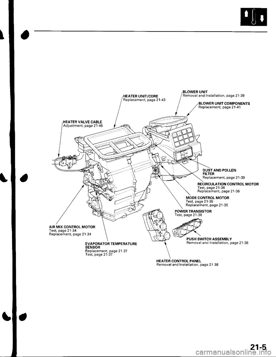
HEATER UNIT/COREBeplacement, page 21-43
BLOWEN UNITRemoval and Installation, page 21-39
HEATER VALVE CABLEAdjustment, page 21-46
BLOWER UNIT COMPONENTSReplacement, page 21-41
DUSTAND POLLENFILTERReplacement, page 21'39
RECIRCULATION CONTROL MOTORTest, page 21-36Replacement, page 21-36
MODE CONTROL MOTORTest, page 21-35Replacement, page 21-35
AIR MIX CONTROL MOTORTest, page 21'34Replacement, page 21'34
POWER TRANSISTORTest, page 21-38
HEATER CONTROL PANELRemovaland Installation, page 21 38
PUSH SWITCH ASSEMBLYRemoval and Installation, page 21'38EVAPORATOR TEMPERATURESENSORReplacement, page 21-37Test, page 21-37
21-5
Page 780 of 1139
Heating and Air Conditioning
General Troubleshooting Information
How to Retrieve a DTC
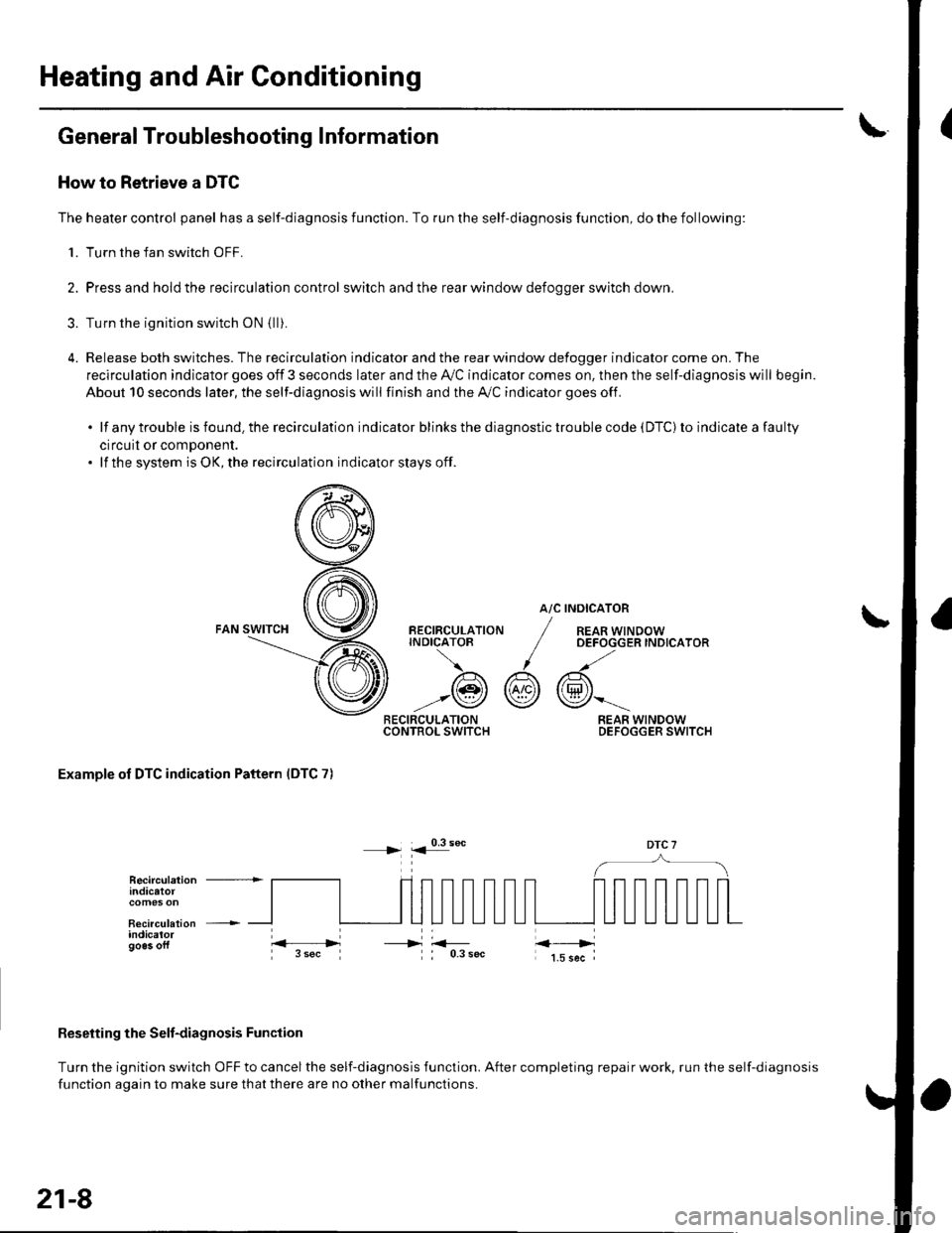
The heater control panel has a self-diagnosis function. To run the self-diagnosis function, do the following:
1. Turn the fan switch OFF.
2. Pressand holdthe recirculation control switch andthe rear window defoooer switch down.
3. Turn the ignition switch oN {lli.
4. Release both switches. The recirculation indicator and the rear window defogger indicator come on. The
recirculation indicator goes off 3 seconds later and the Ay'C indicator comes on. then the self-diagnosis will begin.
About 10 seconds later, the self-diagnosis will finish and the A,/C indicator goes off.
.lfanytroubleisfound.therecirculationindicatorblinksthediagnostictroublecode(DTC)toindicateafaulty
circuil or comDonent.. lf the system is OK, the recirculation indicator stays off.
atc
@r
RECIRCULATIONCONTROL SWITCH
BECIRCULATIONINDICATOB
/A\
-:@
INOICATOR
REAR WINDOWOEFOGGER INDICATOR
REAR WINDOWDEFOGGER SWITCH
Examole of DTC indication Pattern IDTC 7)
DTC 7
Reseiting the Selt-diagnosis Function
Turn the ignition switch OFF to cancel the self-diagnosis function. After completing repair work, run the self-diagnosis
function aoain to make sure thatthere are no other malfunctions.
Recirculation +indicatot
Recirculation +indicalorgo6s oft----->
21-8
Page 781 of 1139
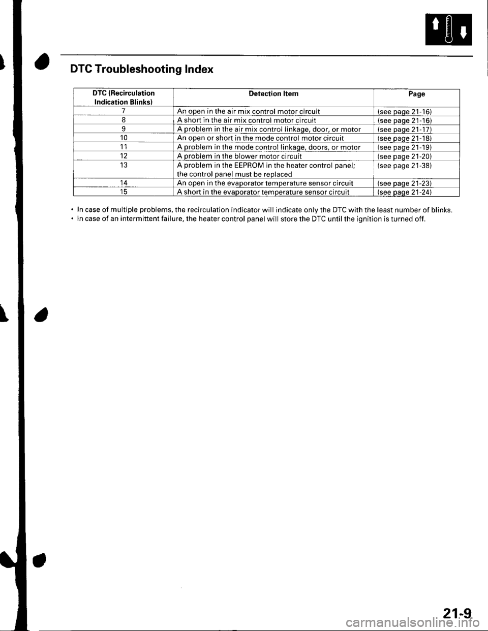
DTC Troubleshooting Index
In case of multiple problems, the recirculation indicator will indicate only the DTC with the least number of blinks.
ln case of an intermittent failure, the heater control panel will store the DTC until the ignition is turned off.
DTC {Recirculation
Indication Blinks)
Detection ltemPage
7An open in the air mix control motor circuit(see paqe 21-16)
8A short ln the air mix control motor circuit(see Daoe 21-'16)
9A problem in the air mix control linkaqe, door, or motor(see paqe 21- 17)
10An open or shon in the mode control motor circuit(see oaqe 21-18)
11A problem in the mode control linkage, doors, or motor(see paqe 21191
12A problem in the blower motor circuit(see paqe 21-20)
13A problem in the EEPROM in the heater control panel;
the control oanel must be reolaced
(see page 21-38)
14An ooen in the evaDorator temDerature sensor circuit(see paqe 21-23)
A short in the evaDoralor temoerature sensor circuit(see oaqe 21-241
21-9
Page 782 of 1139
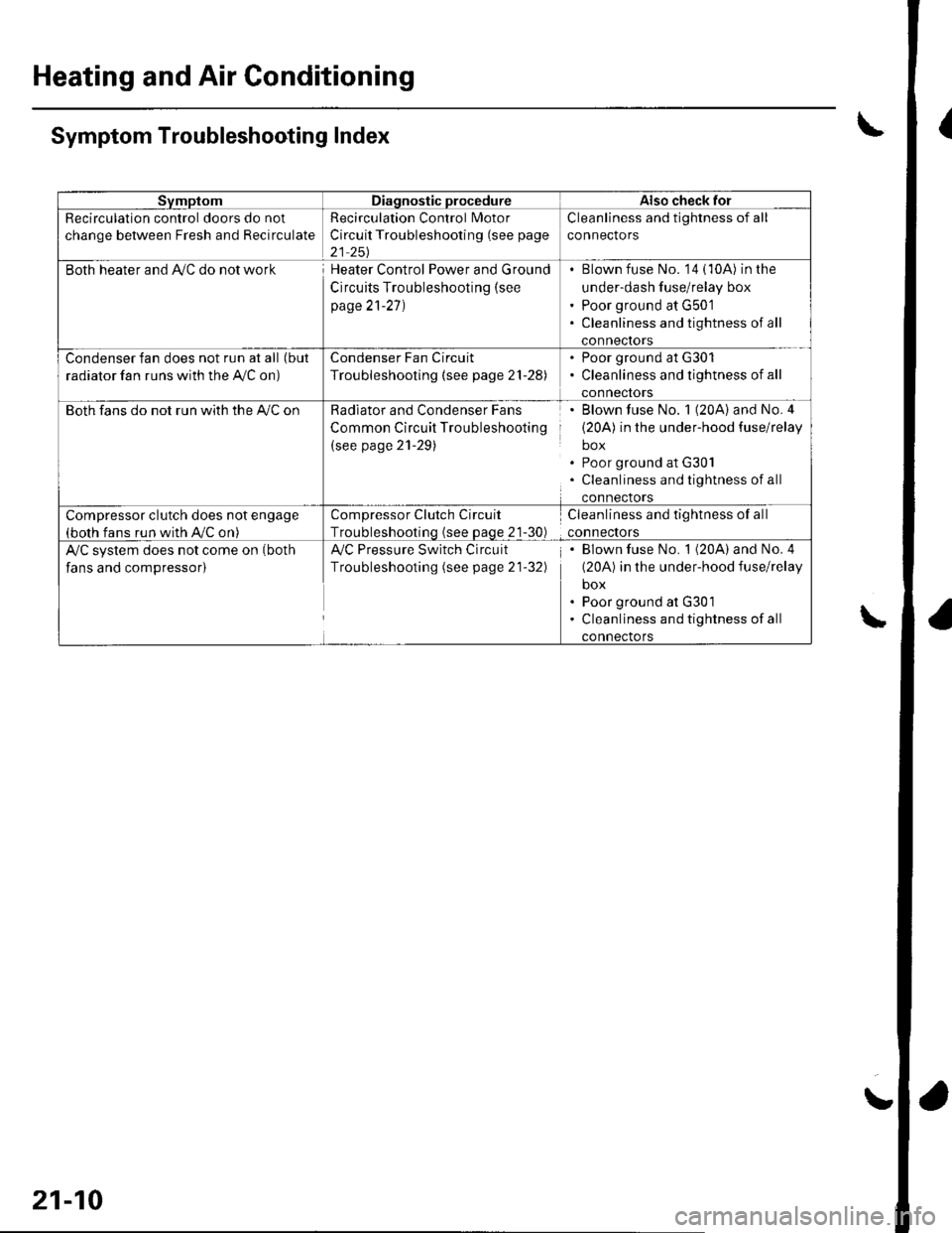
Heating and Air Conditioning
{
a
a
SvmptomDiagnostic procedureAlso check for
Recirculation control doors do not
change between Fresh and Recirculate
Recirculation Control Motor
Circuit Troubleshooting (see page
21 251
Cleanliness and tightness of all
connectors
Both heater and Ay'C do not workHeater Control Power and Ground
Circuits Troubleshooting (see
page 21-27)
Blown fuse No. '14 (10A) in the
under-dash fuse/relay box
Poor ground at G501
Cleanliness and tightness of all
conneclors
Condenser fan does not run at all (but
radiator fan runs with the Ay'C on)
Condenser Fan Circuit
Troubleshooting {see page 21-28)
. Poor ground at G301. Cleanliness and tightness of all
connectors
Both fans do not run with the A,/C onRadiator and Condenser Fans
Common Circuit Troubleshooting
(see page 21-29)
Blown fuse No. 1 (20A) and No.4
(20A) in the under-hood fuse/relay
box
Poor ground at G30l
Cleanliness and tightness of all
connectors
Compressor clutch does not engage(both fans run with A,/C on)
Compressor Clutch Circuit
Troubleshootinq (see Daqe 21-30)
Cleanliness and tightness of all
connectors
A/C system does not come on (both
fans and compressor)
Ay'C Pressure Switch Circuit
Troubleshooting (see page 21-32)
Blown fuse No. 1 (20A) and No. 4
(20A) in the under-hood fuse/relay
box
Poor ground at G301
Cleanliness and tightness of all
connectors
\Symptom Troubleshooting Index
\
21-10
!