Control HONDA CIVIC 2003 7.G Workshop Manual
[x] Cancel search | Manufacturer: HONDA, Model Year: 2003, Model line: CIVIC, Model: HONDA CIVIC 2003 7.GPages: 1139, PDF Size: 28.19 MB
Page 798 of 1139
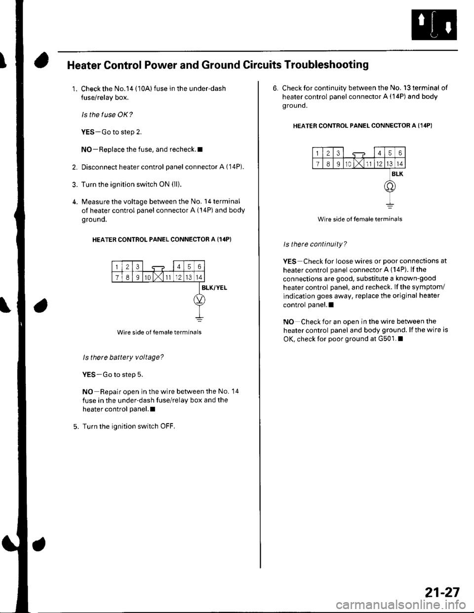
Heater Control Power and Ground Circuits Troubleshooting
1. Check the No.14 (10A)fuse in the under-dash
fuse/relay box.
ls the f use OK?
YES-Go to step 2.
NO-Replace the fuse, and recheck.l
2. Disconnect heater control panel connectorA{'14P).
3. Turn the ignition switch oN (ll).
4. Measure the voltage between the No. l4terminal
of heater control panel connector A (14P) and body
grouno.
HEATER CONTROL PANEL CONNECTOR A {14P}
23456
78I10 l,111214
Wire side of temale terminals
BLK/YEL
ls there battery voltage?
YES-Go to step 5.
NO Repair open in the wire betvveen the No. 14
fuse in the under-dash fuse/relay box and the
heater control panel.l
Turn the ignition switch OFF.
6. Check for continuity between the No. l3terminal of
heater control panel connector A (14P) and body
g rou nd.
HEATER CONTRoL PANEL CONNEcToR A (1ilP)
123456
I89r0 t,1l1214
BLK
.o
Wire side of temaleterminals
ls therc continuity?
YES Check for loose wires or poor connections at
healer control panel connector A (14P). lfthe
connections are good, substitute a known-good
heater control panel, and recheck. lf the symptom/
indication goes away, replace the original heater
control panel.l
NO Check for an open in the wire between the
heater control panel and body ground. lf the wire is
OK, check for poor ground at G501. I
21-27
Page 803 of 1139
Heating and Air Conditioning
Compressor Clutch Circuit
Troubleshooting (cont'dl
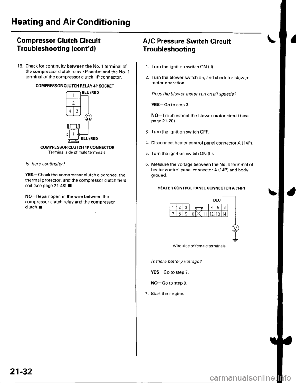
16. Check for continuity between the No. lterminal of
the compressor clutch relav 4P socket and the No. l
terminal of the compressor clutch 1P conneclor.
COMPRESSON CLUTCH RELAY 4P SOCKET
COMPRESSOR CLUTCH 1P CONNECTORTerminal side of male terminals
ls therc continuity?
YES-Check the compressor clutch clearance, the
thermal protector, and the compressor clutch field
coil (see page 21-48).I
NO-Repair open in the wire between the
compressor clutch relay and the compressor
clutch.l
21-32
A/C Pressure Switch Circuit
Troubleshooting
'1. Turn the ignition switch ON {ll).
2. Turn the blower switch on, and check for blower
motor operatron.
Does the blower motor run on all speeds?
YES Go to step 3.
NO Troubleshoot the blower motor circuit (see
page 21-20).
3. Turn the ignition switch OFF.
4. Disconnect heater control panel connectorA ('14P).
5. Turn the ignition switch ON (ll).
6. Measure the voltage between the No, 4 terminal of
heater control panel connector A {14P) and body
grou nd.
HEATER CONTROL PANEL CONNECTOR A (I4P}
1.
ls there battety voltage?
YES Go to step 7.
NO-Go to step 9.
Stan the engine.
Wire side of female termina's
Page 804 of 1139
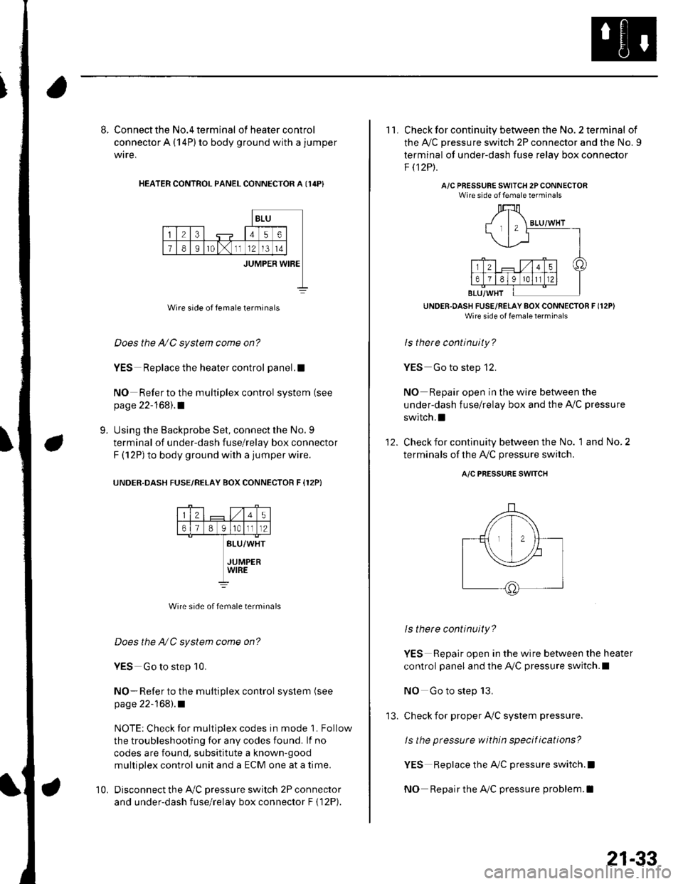
8. Connect the No.4 terminal ofheatercontrol
connector A (14P) to body ground with a jumper
wire,
HEATER CONTROL PANEL CONNECTOR A I14P}
BLU
23456
78Ir0lx1112l3t4
JUMPER WIBE
Wire side of female terminals
Does the A/C system come on?
YES Replace the heater control panel.!
NO Refer to the multiplex control system (see
page 22-168).1
Using the Backprobe Set, connect the No. 9
terminal of under-dash fuse/relay box connector
F (12P) to body ground with a jumper wire.
UNOER.DASH FUSE/RELAY BOX CONNECTOR F {12P}
9.
25
61B g lrotll2
BLU/WHT
JUMPERWIRE
Wire side of female terminals
Does the NC system come on?
YES Go to step 10.
NO- Refer to the multiplex control system (see
page 22-168).1
NOTE: Check for multiplex codes in mode '1. Follow
the troubleshooting {or any codes found. lf no
codes are found, subsititute a known-9ood
multiplex control unit and a ECM one at a time.
Disconnect the Ay'C pressure switch 2P connector
and under-dash fuse/relay box connector F { 12P).
10.
'13.
21-33
11. Check for continuity between the No. 2 terminal of
the A,/C pressure switch 2P connector and the No. 9
terminal of under-dash fuse relav box connector
F t12Pt.
A/C PRESSURE SWITCH 2PCONNECTORWire side of female terminals
UNDER.OASH FUSE/RELAY BOX CONNECTOR F (12P)
Wire side of fenale lerrrinal'
ls there continuity?
YES Go to step 12.
NO Repair open in the wire between the
under-dash fuse/relay box and the A,,/C pressure
switch.I
Check for continuity between the No. 1 and No. 2
terminals of the A,/C pressure switch.
12.
A/C PRESSURE SWITCH
ls there continuity?
YES Repair open in the wire between the heater
control panel and the A,/C pressure switch.l
NO Go to step 13.
check for proper Ay'C system pressure.
ls the pressure within specitications?
YES Replace the AilC pressure switch.l
NO Repair the AilC pressure problem.I
Page 805 of 1139
Heating and Air Conditioning
Air Mix Control Motor Test
1. Disconnect the 5P connector from the air mix
control motor.
2. Connect battery powertothe No. l terminal ofthe
air mix control motor, and ground the No. 2
terminal; the air mix control motor should run, and
stop at Max Cool. lf it doesn't, reverse the
connections;the air mix control motor should run,
and stop at Max Hot. lf the air mix control motor
does not run, remove it. then check the air mix
control linkage and door for smooth movement.
. lf the linkage and door move smoothly, replace
the air mix control motor.. lf the linkage ordoorstickor bind, repairthem as
needed.. lf the air mix control motor runs smoothly, go to
step 3.
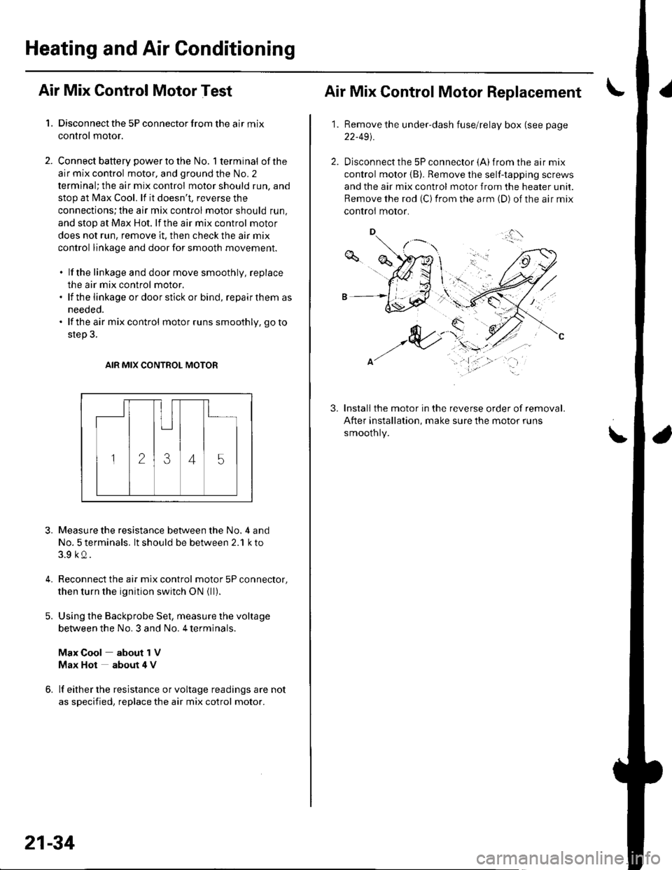
AIR MIX CONTROL MOTOR
3.
4.
Measure the resistance between the No. 4 and
No. 5 terminals. lt should be between 2.1 k to
3.9 kQ.
Reconnect the air mix control motor 5P connector,
then turn the ignition switch ON {ll).
Using the Backprobe Set, measure the voltage
between the No. 3 and No. 4 terminals.
Max Cool about 1V
Max Hot about 4 V
lf either the resistance or voltage readings are not
as specified, replace the air mix cotrol motor.
21-34
Air Mix Control Motor Replacement
1.Remove the under-dash fuse/relay box (see page
22-491.
Disconnect the 5P connector {A) from the air mix
control motor (B). Remove the self-tapping screws
and the air mix control motor from the heater unit.
Remove the rod (C) from the arm (D) of the air mix
controi motor.
Install the motor in the reverse order of removal.
After installation, make sure the motor runs
smoothly.
3.
\'
,.,:l'
Page 806 of 1139
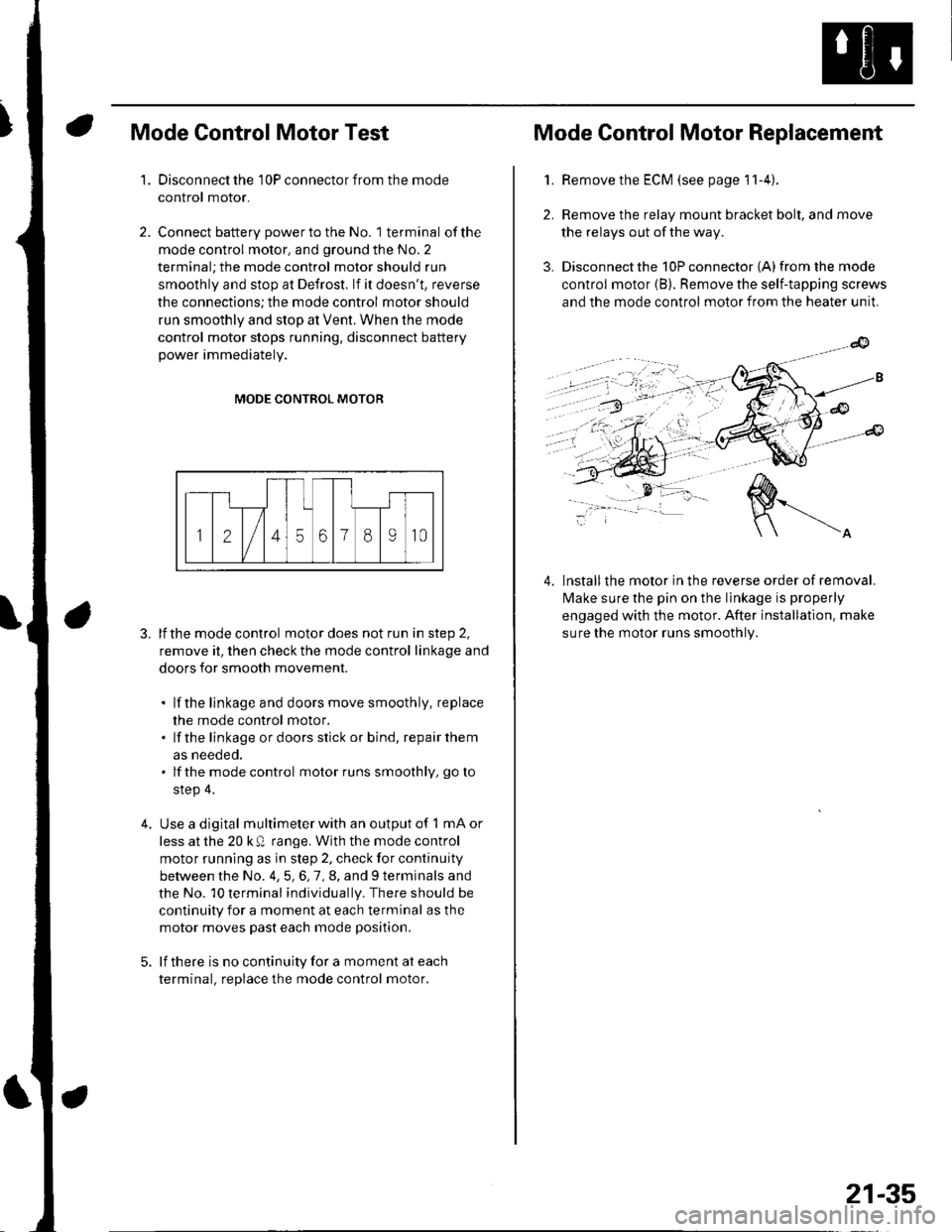
Mode Control Motor Test
Disconnect the 10P connector from the mode
control motor.
Connect battery power to the No. 1 terminal of the
mode control motor, and ground the No. 2
terminal; the mode control motor should run
smoothly and stop at Defrost. lf it doesn't, reverse
the connections; the mode control motor should
run smoothly and stop at Vent. When the mode
control motor stops running, disconnect battery
power immediately.
'1.
4.
MODE CONTROL MOTOR
3. lfthe mode control motor does not run in step 2,
remove it, then check the mode control linkage and
doors for smooth movement.
. lf the linkage and doors move smoothly. replace
the mode control motor.. lf the linkage ordoorsstick or bind, repairthem
as neeoeo.. lfthe mode control motor runs smoothly, go to
step 4.
Use a digital multimeter with an output of 1 mA or
less at the 20 k Q range. With the mode control
motor running as in step 2, check for continuity
between the No. 4,5,6,7,8, and 9 terminals and
the No. 10 terminal individually. There should be
continuity for a moment at each terminal as the
motor moves past each mode position.
lf there is no continuity for a moment at each
terminal. replace the mode control motor.
Mode Control Motor Replacement
2.
3.
1.Remove the ECM (see page 11-4).
Remove the relay mount bracket bolt, and move
the relays out of the way.
Disconnect the 10P connector {A) from the mode
control motor (B). Remove the self-tapping screws
and the mode control motor from the heater unit.
lnstallthe motor in the reverse order of removal.
lvlake sure the pin on the linkage is properly
engaged with the motor. After installation. make
sure the motor runs smoothly.
4.
21-35
Page 807 of 1139
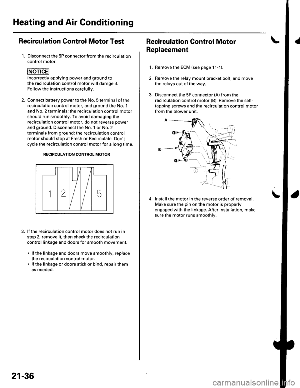
Heating and Air Conditioning
Recirculation Control Motor Test
1. Disconnect the 5P connector from the recirculation
control motor.
Incorrectly applying power and ground to
the recirculation control motor will damge it.
Follow the instructions carefullv.
2. Connect batterv oower to the No. 5 terminal ofthe
recirculation control motor, and ground the No. 1
and No. 2 terminals; the recirculation control motor
should run smoothly. To avoid damaging the
recirculation control motor, do not reverse power
and ground. Disconnect the No. 1 or No. 2
terminals from ground; the recirculation control
motor should stop at Fresh or Recirculate. Don't
cycle the recirculation control motor {or a long time.
RECIRCULATION CONTROL MOTOR
lf the recirculation control motor does not run in
step 2, remove it, then check the recirculation
control linkage and doors for smooth movement.
. lfthe linkage and doors move smoothly, replace
the recirculation control motor.. lf the linkageordoorsstickor bind, repairthem
as neeoeo.
21-36
Recirculation Control MotorI
Replacement
1.Remove the ECM (see page 11-4).
Remove the relay mount bracket bolt. and move
the relays out of the way,
Disconnect the 5P connector (A) from the
recirculation control motor (B), Remove the self-
tapping screws and the recirculation control motor
from the blower unit.
Installthe motor in the reverse order of removal.
Make sure the pin on the motor is properly
engaged with the linkage. After installation. make
sure the motor runs smoothly.
\
Page 809 of 1139
Heating and Air Gonditioning
a
\
Power Transistor Test
1. Disconnect the 4P connector from the power
Iranslslor.
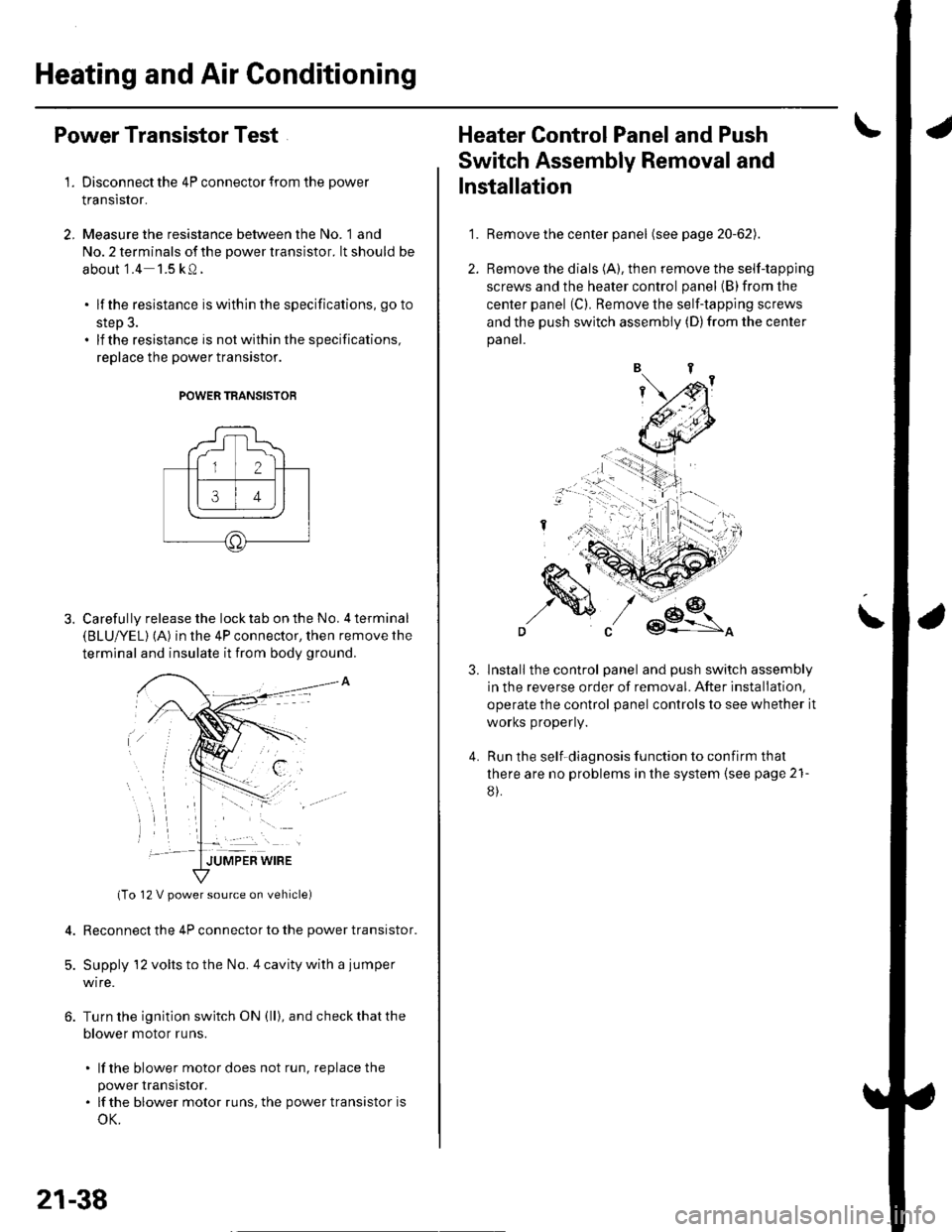
2, Measure the resistance between the No. 1 and
No. 2 terminals of the power transistor. lt should be
about '1.4 1.5 kQ.
. lf the resistance iswithln the specifications, go to
step 3.. lf the resistance is notwithin the specifications,
replace the power transistor.
POWER TRANSISTOB
Carefully release the lock tab on the No. 4 terminal(BLUI/EL) (A) in the 4P connector, then remove the
terminal and insulate it from body ground.
(To 12 V power source on vehicle)
Reconnect the 4P connector to the power transistor.
Supply 12 volts to the No. 4 cavity with a jumper
wire.
Turn the ignition switch ON (ll), and check that the
blower motor runs.
. lf the blower motor does not run, replace the
power rranstsror.. lf the blower motor runs,the powertransistoris
oK.
12 V power source on vehicle)
21-38
1.
Heater Control Panel and Push
Switch Assembly Removal and
Installation
Remove the center panel (see page 20-62).
Remove the dials (A), then remove the self-tapping
screws and the heater control panel (B)from the
center panel (Cl. Remove the self-tapping screws
and the push switch assembly (D)from the center
panel.
lnstall the control panel and push switch assembly
in the reverse order of removal. After installation,
operate the control panel controls to see whether it
worKs propeny.
Run the self-diagnosis function to confirm that
there are no problems in the system (see page 21-
8).
3.
4.
Page 811 of 1139
Heating and Air Gonditioning
Blower Unit Removal and Installation {cont'd}
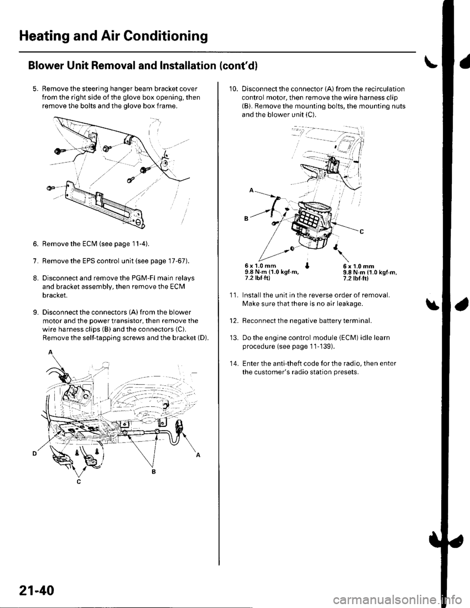
Remove the steering hanger beam bracket cover
from the right side of the glove box opening, then
remove the bolts and the olove box frame.
1.
8.
9.
Remove the ECM (see page 11-4).
Remove the EPS control unit (see page 17-67).
Disconnect and remove the PGM-Fl main relays
and bracket assembly, then remove the ECM
bracket.
Disconnect the connectors {A) from the blower
motor and the power transistor, then remove the
wire harness clips (B) and the connectors (C).
Remove the self-tapping screws and the bracket (D).
A
21-40
10. Disconnectthe connector {A) from the recirculation
control motor, then remove the wire harness clip
{B). Remove the mounting bolts, the mounting nuts
and the blower unit (C).
6x 1.0 mm I9.8 N.m (1.0 kgt.m,7.2 tbt.ftl
6x1.0mm9.8 N.m (1.0 kgf.m,?.2 tbf.ft)
11.
14.
Installlhe unit in the reverse order of removal.
Make sure that there is no air leakage.
Reconnect the negative battery terminal.
Do the engine control module (ECM) idle learn
procedure {see page 11-139).
Enter the anti-theft code for the radio, then enter
the customer's radio station presets.
\
'13.
Page 812 of 1139
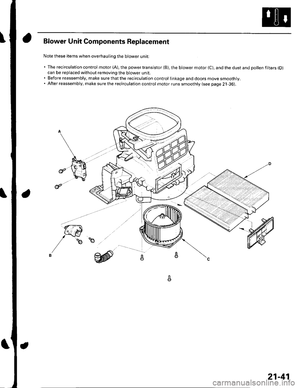
Blower Unit Components Replacement
Nole these items when overhauling the blower unit;
' The recirculation control motor (A), the power transistor (B), the blower motor (C), and the dust and pollen filtefs (D)
can be replaced without removing the blower unit.. Before reassembly, make surethatthe recirculation control linkage and doors move smoothly.. After reassembly, make surethe recirculation control motorruns smoothly (see page 2j-36).
A
21-41
Page 815 of 1139
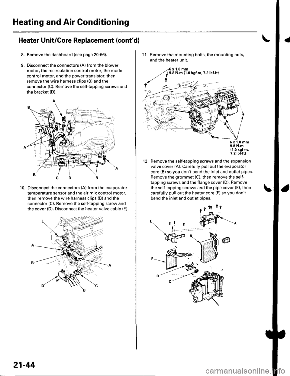
Heating and Air Conditioning
Heater Unit/Core Replacement (cont'd)
8. Remove the dashboard {see page 20-66).
9. Disconnectthe connectors (A) from the blower
motor, the recirculation control motor, the mode
control motor, and the power transistor, then
remove the wire harness clips (B) and the
connector (C). Remove the self-tapping screws and
the bracket (D).
Disconnect the connectors (A) from the evaporator
temperature sensor and the air mix control motor,
then remove the wire harness clips (B) and the
connector (C). Remove the self-tapping screw and
the cover (D). Disconnect the heater valve cable (E).
10,
7t,
21-44
11. Remove the mounting bolts, the mounting nuts,
and the heater unit.
Remove the self-tapping screws and the expansion
valve cover (A). Carefully pull out the evaporator
core (B) so you don't bend the inlet and outlet pipes.
Remove the grommet (C), then remove the self-
tapping screws and the flange cover (D). Bemove
the self-tapping screws and the pipe cover (E), then
carefully pull out the heater core (F) so you don't
bend the inlet and outlet oioes.
@
5x 1.0 mm9.8 N.m11.0 kgl m,7.2 tbf.ftl
12.