Control HONDA CIVIC 2003 7.G Workshop Manual
[x] Cancel search | Manufacturer: HONDA, Model Year: 2003, Model line: CIVIC, Model: HONDA CIVIC 2003 7.GPages: 1139, PDF Size: 28.19 MB
Page 816 of 1139
13. Installthe heater core and the evaporator core in
the reverse order of removal.
14. Installthe heater unit in the reverse order of
removal, and note these items:
. Do not interchange the inlet and outlet heater
hoses, and installthe hose clamps securely.. Refillthe cooling system with engine coolant (see
page 10-6).. Adjust the heater valve cable (see page 2'l-461.. Make sure that there is no coolant leakage.. Make sure that there is no air leakage.. Refer to evaporator core replacement {see step 6
on page 21-42).. Do the engine control module (ECl\4) idle learn
procedure (see page 11-139).. Enter the anti-theft code for the radio, then enter
the customer's radio station Dresets.
21-45
Page 817 of 1139
Heating and Air Conditioning
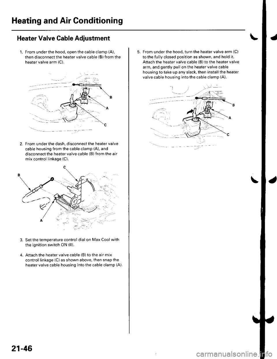
Heater Valve Cable Adjustment
1. From underthe hood, open the cable clamp {A),
then disconnect the heater valve cable (B) from the
heater valve arm {C).
tFrom under the dash, disconnect the heater valve
cable housing from the cable clamp (A), and
disconnect the heater valve cable (B) from the air
mix control linkage {C).
, t.- l
\'r2t' ''' '
' ::"'
Set the temperature control dial on Max Cool with
the ignition switch ON (ll).
Attach the heater valve cable (B) to the air mix
control linkage (C) as shown above, then snap the
heater valve cable housing into the cable clamp (A).
.'.-:',,
-"ll
.....-
21-46
5, From under the hood, turn the heater valve arm {C)
to the fully closed position as shown, and hold it.
Attach the heater valve cable (B) to the heater valve
arm, and gently pull on the heater valve cable
housing to take up any slack, then install the heater
valve cable housing into the cable clamp (A).
.
\
Page 818 of 1139
Compressor Replacement
1. lf the compressor is marginally operable, run the
engine at idle speed, and let the air conditioning
work for a few minutes, then shut the engine off.
2. Make sure you have the anti-theft code for the radio,
then write down the frequencies for the radio's
preset buttons.
3. Disconnect the negative cable from the battery.
4. Recover the refrigerant with a recovery/recycling/
charging station (see page 21-53).
5. Remove the alternator (see page 4-29).
6. Remove the Ay'C condenser fan assembly (see page
10-10).
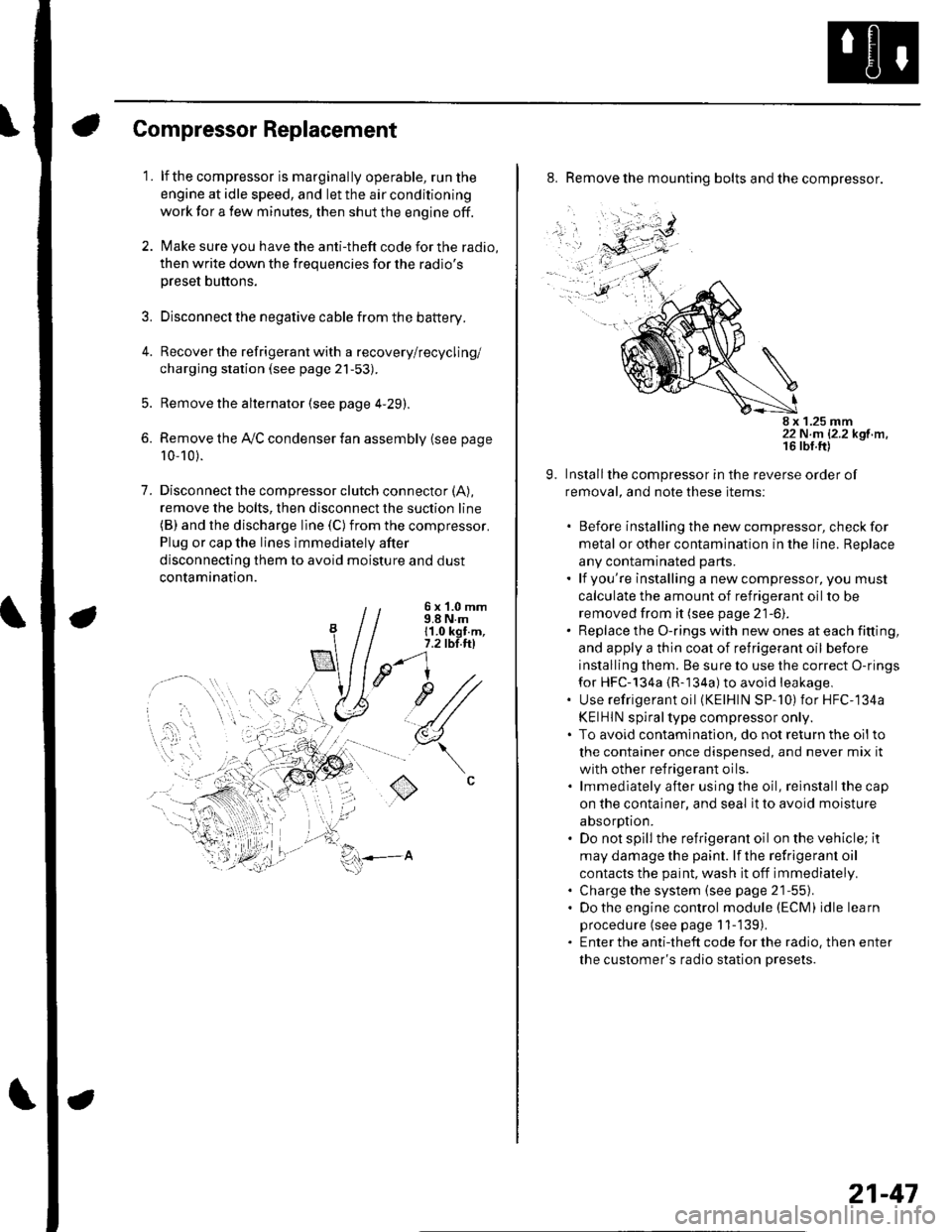
7. Disconnectthe compressor clutch connector (A),
remove the bolts, then disconnect the suction line(B) and the discharge line (C)from the compressor.
Plug or cap the lines immediately after
disconnecting them to avoid moisture and dust
contamination.
6 x '1.0 mm9.8 N.m11.0 kgt.m,7.2 tbl.ttl
u1/
(
o
8. Remove the mounting bolts and the compressor.
8 x 1.25 mm22 N.m 12.2 kgf.m.
9. Installthe compressor in the reverse order of
removal, and note these items:
. Before installing the new compressor, check for
metal or other contamination in the line. Replace
any contaminated parts.. lf you're installing a newcompressor, you must
calculate the amount of refrigerant oil to be
removed from it (see page 21-6).. Replace the O-rings with new ones at each fitting,
and apply a thin coat of refrigerant oil before
installing them. Be sure to use the correct O-rings
for HFC-134a {R-134a) to avoid leakage,. Use refrigerant oil (KElHlN SP-'10) for HFC-134a
KEIHIN spiral type compressor only.. To avoid contaminatlon, do not return the oilto
the container once dispensed, and never mix it
with other refrigerant oils.. lmmediately after using the oil, reinstallthe cap
on the container, and seal it to avoid moisture
absorption.. Do not spill the refrigerant oil on the vehicle; it
may damage the paint. lf the refrlgerant oil
contacts the paint, wash it off immediately.. Charge the system (see page 21-55).. Do the engine control module (ECM) idle learn
procedure (see page 11-'139).. Enter the antitheft code for the radio, then enter
the customer's radio station presets.
21-47
Page 829 of 1139
Heating and Air Conditioning
A/C System Tests (cont'd)
1.
Performance Test
Air conditioning refrigerant or lubricant vapor
can irritate your eyes, nose, or throar.
Be carefulwhen connecting service equipment.
Do not breathe refrigerant or vapor.
The performance test will help determine if the air
conditioner system is operating within specifications.
Use only service equipment that is U.L.-listed and is
cenified to meet the requirements of SAE J2210 toremove HFC-134a (R-134alfrom the air conditioning
system.
lf accidental system discharge occurs, ventilate the
work area before resuming service
R-134a service equipment or vehicle air conditioning
systems should not be pressure tested or leak testedwith compressed air.
Additional health and safety information may be
obtained from the refrigerant and lubricant
manufacturers.
Connect a R-134a refrigerant recover/recycling/
charging station to the high-pressure service port
and the low-pressure service port, following the
equipment manufacturer's instructions.
Determine the relative humidity and air
Iemperaru re.
' Compressed air mixed with R-134a forms a
combustible vapor.. The vapor can burn or explode causing serious
Injury.. Never use compressed air to pressure test
R-134a service equipment or vehicle air
conditioning systems.
21-58
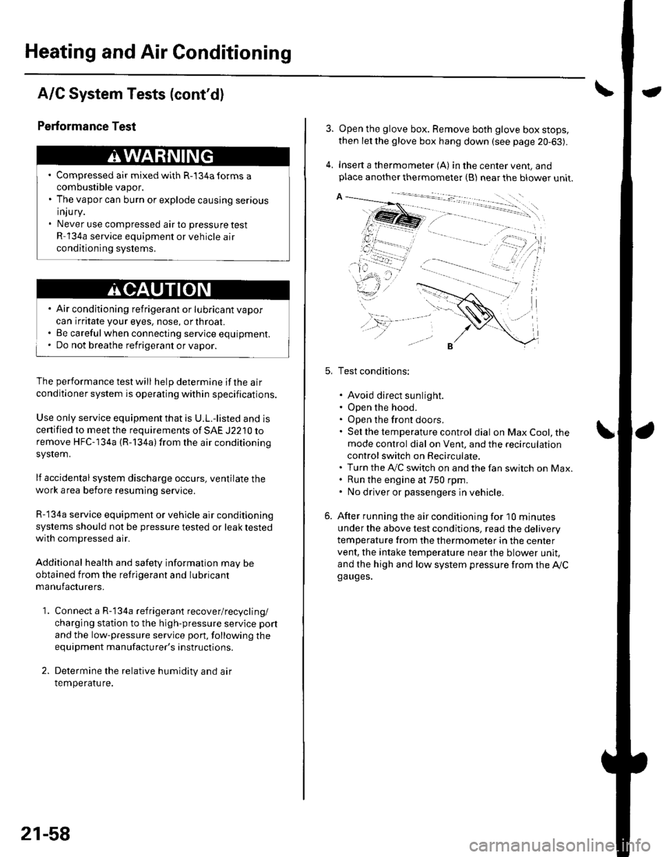
4.
Open the glove box. Remove both glove box stops,
then let the glove box hang down (see page 20-63).
Insert a thermometer (A) in the center vent, andplace another thermometer {B) near the blower unit.
Test conditions:
. Avoid direct sunlight.. Open the hood.. Open the front doors.. Sel the temperature control dial on Max Cool, the
mode control dial on Vent, and the recirculation
control switch on Recirculate.. Turn the A,/C switch on and the fan switch on Max.. Run the engine at 750 rpm.. No driver or passengers in vehicle.
After running the air conditioning for I0 minutes
under the above test conditjons, read the delivery
temperature from the thermometer in the center
vent, the intake temperature near the blower unit,
and the high and low system pressure from the Ay'Cga uges.
Page 831 of 1139
\Body Electrical
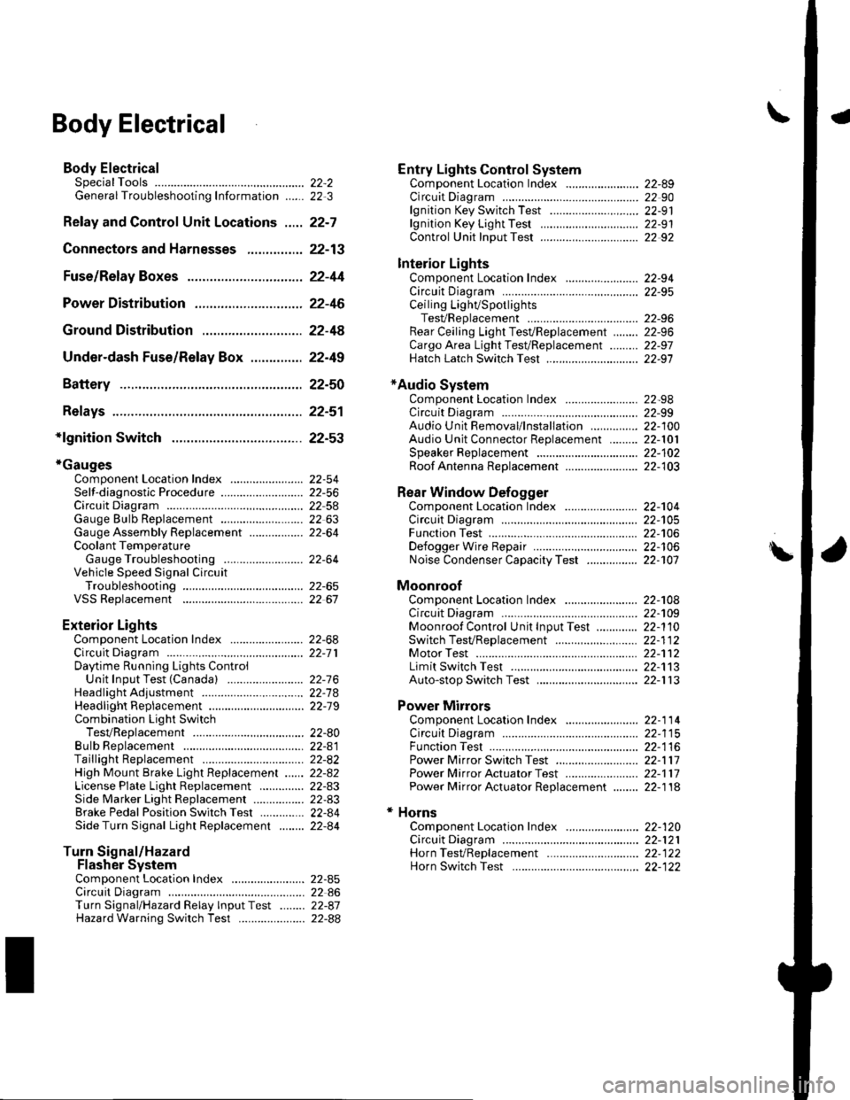
Body ElectricalSpecialToolsGeneral Troubleshooting tntorrnaiion.'......
Relay and Control Unit Locations .....
Connectors and Harnesses
Fuse/Relay Boxes ...............................
Power Distribution .............................
Ground Distribution ...........................
Under-dash Fuse/Relay Box ..............
Battery ..............
Relays ................
*lgnition Switch ..............
*Gauges
Component Location Index .......................Self-diagnostic Procedure ..........................Circuit DiagramGauge Bulb Replacement ..........................Gauge Assembly ReplacementCoolant Temperature
Gauge Troubleshooting .... ....................Vehicle Speed Signal CircuitTroubleshootingVSS Replacement
Exterior LightsComponent Location Index .......................Circuit DiagramDaytime Running Lights ControiUnit Input Test (Canada) ........................Headlight Ad,ustment .................. .. .....Headlighr Replacement ..............................Combination Light SwitchTest/ReplacementBulb ReplacementTaillight Replacement ..........................High Mount Brake Light Replacement ......License Plate Light Replacement ..............Side Marker Light Replacement ................Brake Pedal Position Switch Test ..............Side Turn Signal Light Replacement ........
Turn Signal/HazardFlasher SystemComponent Location Index .......................Circuit DiagramTurn Signal/Hazard Relay lnputTest ........Hazard Warning Switch Test
22,3
22-7
22-13
22-44
22-46
22-4A
22-49
22-50
22-51
22-53
22-5422-5622-5422 6322-64
22-64
22-6522 61
22-6822--71
22-7 622-7422-79
22-AO22-4122-8222-4222-4322-4322-4422-84
22-8�522 A622-8722-88
22-10422-105
22-10622-107
Entry Lights control systemComponent Location Index ....................... 22-89Circuit Diagram ......... 22 90lgnition Key Switch Test .....................,...... 22-9'llgnition Key Light Test ............................... 22-91Control Unit Input Test ..........,.................... 22 92
Interior LightsComponent Location Index ....................... 22-94Circuit Diagram ......... 22-95Ceiling LighVSpotlightsTesVReplacement ................................... 22-96Rear Ceiling Light TesVReplacem ent ........ 22-96Cargo Area Light Test/Replacem ent ......... 22-97Hatch Latch Switch Test ..,..,....................... 22-97
*Audio SystemComponent Location Index ....................... 22-98Circuit Diagram ......... 22,99Audio Unit Removal/lnstallation ............... 22-1OOAudio Unit Connector Replacement ......... 22-101Speaker Replacement ................................ 22-102Roof Antenna Rep1acement ....................-.. 22-103
Rear Window DefoggerComponent Location Index ...........Circuit Diasram .. ....... .. ..... ....... ...:::::.::.::.Function TestDefogger Wire Repair .................................Noise Condenser CapacityTest ................
MoonroofComponent Location Index ....................... 22-1OBCircuit Diagram ......... 22-109Moonroof Control Unit Input Test ............. 22-'l10Switch TesVReplacement ........,.....,........... 22-1 12Motor Test ................. 22-112Limit Swilch Test ...... 22-'l'13Auto-stop Switch Test ................................ 22-1 13
Power MirrorsComponent Location Index ....................... 22-114Circuit Diagram ......... 22-115Function Test ............. 22-116Power Mirror Switch Test .......................... 22-ll7Power Mirror Actuator Test ....................... 22-117Power Mirror Actuator Replacement ........ 22-11A
* HornsComponent Location Index ....................... 22-120Circuit Diagram ......... 22-121Horn TesVReplacement ...........................-. 22-122Horn Switch Test .,.... 22-122
\
Page 832 of 1139
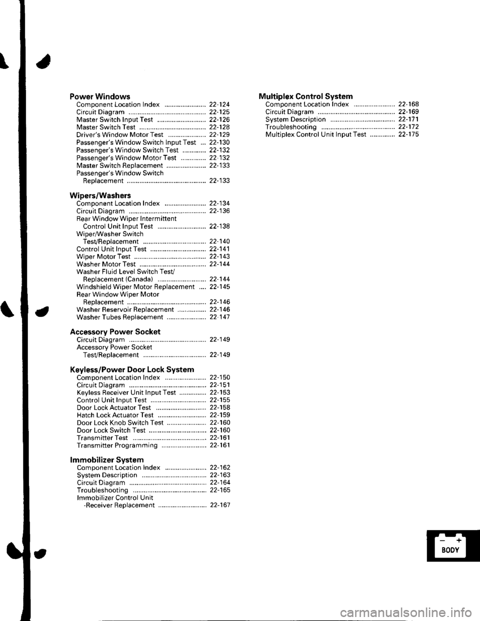
Power WindowsComponent Location Index ..........
circuit Diagram . .. ............... .........:.::::.::::.:Master Switch Input Test ...........................Master Switch TestDriver's Window Motor Test .....................
Passenger's Window Switch lnput Test ...Passenger's Window Switch Test .............
Passenger's Window Motor Test ..............
lMaster Switch Replacement ......................
Passenger's Window SwitchReplacement
Wipers/WashersComponent Location Index .......................
Circuit DiagramRear Window Wiper Intermiftent
Control Unit Input Test ...........................Wiper/Washer SwitchTesVReplacementControl Unit Input Test ...............................Wiper Motor Test
Washer Motor TestWasher Fluid Level Switch TesV
Replacement (Canadal ..........................
Windshield Wiper Motor Replacement ....
Rear Window Wiper MotorReplacementWasher Reservoir Replacement ................
Washer Tubes Beplacement ......................
Accessory Power SocketCircuit Diagram ......... 22-149
Accessory Power Socket
TesVReplacement ................................... 22-1 49
Keyless/Power Door Lock System
Component Location Index ....................... 22-150
Circuit Diagram ......... 22-151Keyless Receiver Unit InputTest ............... 22-153
Control Unit Input Test ............................... 22-155
Door LockActuatorTest .........,.......,..,.,..... 22-158Hatch LockActuatorTest ........................... 22-159
Door Lock Knob Switch Test ...................... 22-160
Door Lock Switch Test ................................ 22-160
Transmitter Test ....... 22-161
Transmitter Programming ......................... 22-161
Multiplex Control SystemComponent Location Index ...........
circuit Diagram ...... ........................::.:..:.::.:
Svstem DescriDtionTroubleshootingMultiolex Control Unit InDut Test .............
22 12422-12522-12622-12822-129
22- t30
22-13222 13222-133
22-133
22-134
22-138
22-14022-14122-14322-144
22-14422-145
22-14622-14622 147
22,16422-16922-17'l22,11222-175
lmmobilizer Systemcomponent Location Index ...........
System Description ....... ............. ..:..:..:.:...
Circuit DiagramTroubleshootinglmmobilizer Control Unit-Receiver Replacement ...........................
22-16222-16322-164
22-167
Page 838 of 1139
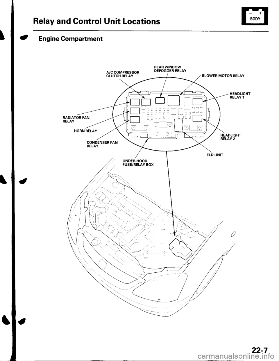
Relay and Control Unit Locations
Engine Compartment
RADIATOR FANRELAY
BLOWER MOTOR RELAY
HORN RELAY
CONDENSER FANRELAY
UNDER-HOODFUSE/RELAY BOX
\...
,-:1-'...
ELD UNIT
22-7
Page 839 of 1139
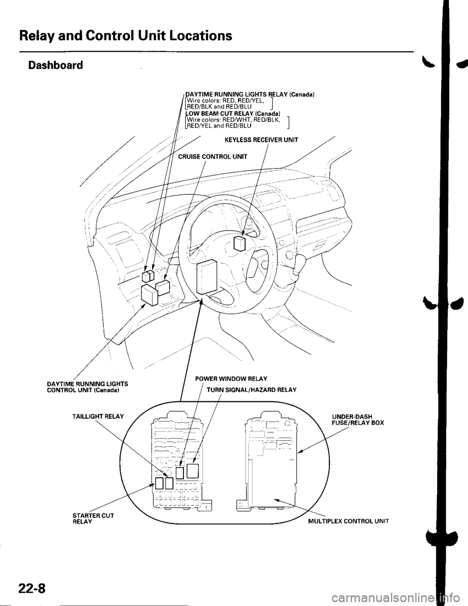
Relay and Gontrol Unit Locations
Dashboard
_DAYTIME RUNNING LIGHTS EELAY lCanada)lWire colorsr RED, RED/YEL, ILRED/BLK and RED/8LU I_LOW BEAM CUT RELAY lcanada) _lWire colors: REDMHT, RED/BLK, ILBEDA/EL and RED/BLU I
KEYLESS RECEIVER UNIT
CRUISE CONTROL UNIT
'
'-.:- ':
..? ;,
POWER WINOOW RELAY
TURN SIGNAL/HAZARD RELAY
TAILLIGHT RELAYUNDER.DASHFUSE/RELAY BOX; .[:_- -
-l:r --
22-8
MULTIPLEX CONTROL UNIT
Page 841 of 1139
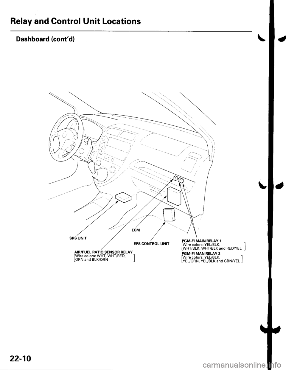
Relay and Control Unit Locations
a
\
Dashboard (cont'd)
L
SRS UNIT
EPS CONTROL UNITPGM.FI MAIN RELAY 1lWire colors: YEUBLK,LWHT/BLK, WHT/BLK and RED/YEL
PGM.FI MAN RELAY 2fwire colors: YEUBLK, ILYEUGRN, YEUBLK and GRN/YEL I
AIR/FUEL RATIO SENSOR RELAY[Wire colorsr WHT, WHT/RED, IOBN and BLK/ORN I
22-10
Page 843 of 1139
![HONDA CIVIC 2003 7.G Workshop Manual Relay and Control Unit Locations
Door and Seat
Drivers Door:
Passengers Seat:
l\:
].\
POWER WINDOW MASTER SWITCHlHas built-in control unit)
22-12 HONDA CIVIC 2003 7.G Workshop Manual Relay and Control Unit Locations
Door and Seat
Drivers Door:
Passengers Seat:
l\:
].\
POWER WINDOW MASTER SWITCHlHas built-in control unit)
22-12](/img/13/5744/w960_5744-842.png)
Relay and Control Unit Locations
Door and Seat
Driver's Door:
Passenger's Seat:
l\:
].\
POWER WINDOW MASTER SWITCHlHas built-in control unit)
22-12