Front HONDA CIVIC 2003 7.G User Guide
[x] Cancel search | Manufacturer: HONDA, Model Year: 2003, Model line: CIVIC, Model: HONDA CIVIC 2003 7.GPages: 1139, PDF Size: 28.19 MB
Page 34 of 1139
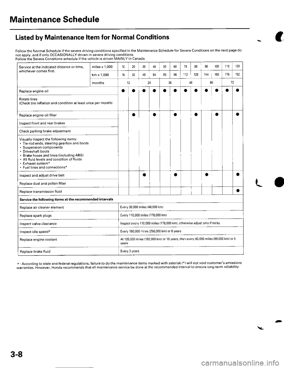
Maintenance Schedule
Service atthe indicated distance ortime,whichever comes first.miles x 1,000t020304050708090 100110r20
km x 1,000163248648096112128144 160192
months12243486012
Replace engine oilooooaooaaoOa
Rotate tires{Check tire intlation and condition at least once per month)
Replace engine oil filterooaaaa
Inspect front and rear brakes
Check parking brake adjustment
Visually inspect the following items:. Tie-rod ends, steering gearbox and boots. Suspension components. Driveshaft boots. Brake hoses and lines (including ABSi. Allfluid levels and condition of{luids. Exhaust system*. Fuel lines and connections*
Inspect and adjust drive beltaaaa
Replace dust and pollen filter
Reolace transmission fluid
Servicethe following items at the recommended intervals
a
Replace air cleaner elementEvery 30,000 miles (48,000 km)
Replace spark plugsEvery 110,000 miles (176,000 Lm)
Inspect valve clearanceInspect every 110,000 miles {176,000 km), otherwise adiusl only if noisy.
Inspect idle speed*Every 160.000 mr es 1256,000 km) or 8 years
Replace engine coolantAt 120,000 miles (192,000 km) or 10 years, then every 60,000 miles (96,000 km) or 5
Replace brake fluidEvery 3 years
Listed by Maintenance ltem for Normal Conditions
Follow the Normal Schedule if the severe driving conditions specified in the lMaintenance Schedule for Severe Conditions on the next page do
not apply, and if only OCCASIONALLY driven in severe driving conditions.Follow the Severe Conditions schedule if the vehicle is driven MAINLY in Canada.
* : According to state and lederal regulations, failure to do the maintenance items marked with asterisk (*) will not void customer's emissions
warranties. However, Honda recommends that all maintenance service be done at the recommended interval to ensure long-term reliability-
c
3-8
Page 35 of 1139
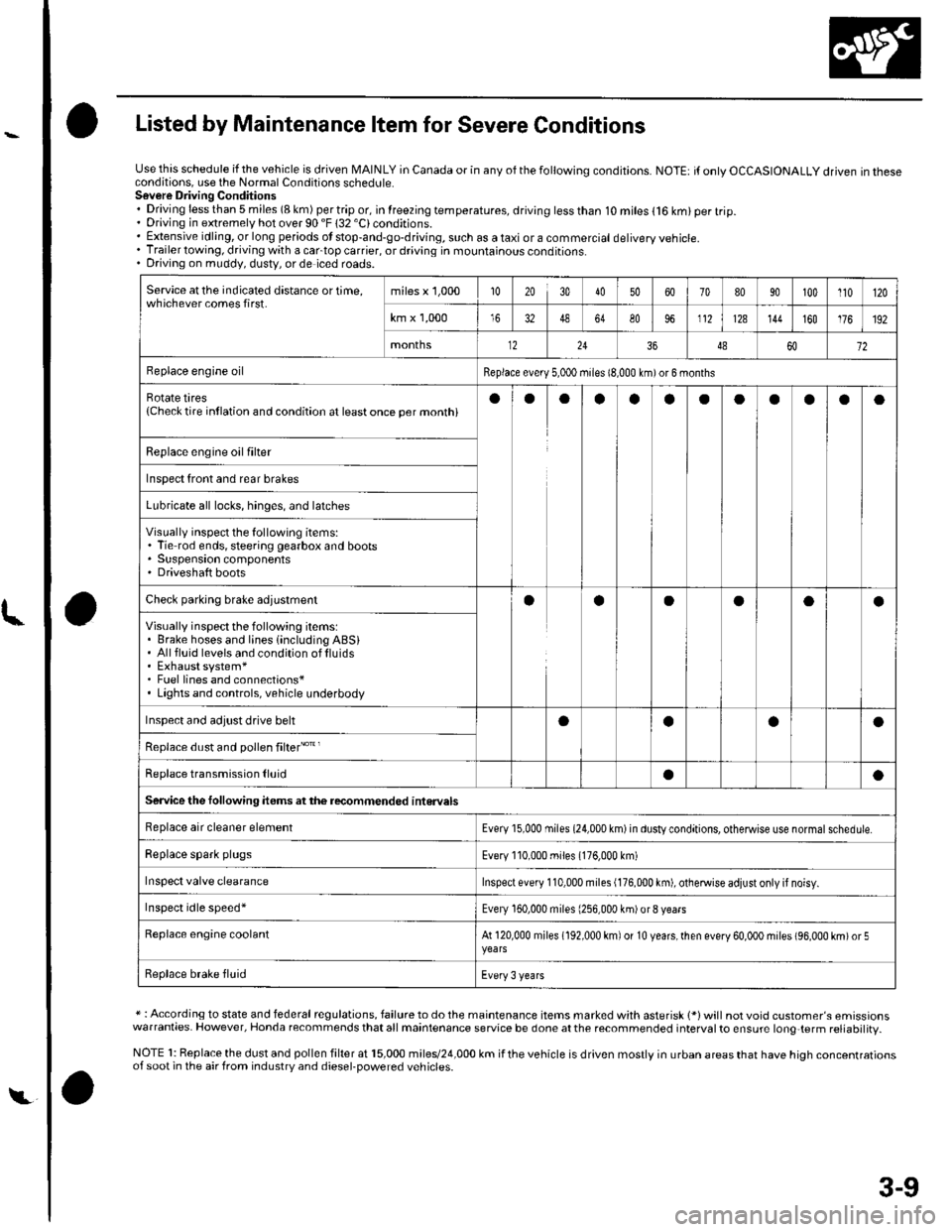
Listed by Maintenance ltem for Severe Conditions
Use this schedule if the vehicle is driven MAINLY in Canada or in anv of the followina conditions.NOTE: it only OCCASIONALLY driven in theseconditions, use the Normal Conditions schedute.Sovere Driving Conditions. Driving less than 5 miles (8 km) per trip or, in lreezing temperatures, driving less than. Driving in extremely hot over 90 "F 132 'C)conditions.10 miles (16 km) per trip.
. Extensive idling, or long periods ot stop-and-go-driving, such as a taxi or a commercial delivery vehicle.. Trailer towing, driving with a cartop carrier, or driving in mountainous conditions.. Driving on muddy, dusty, or de iced roads.
Service at the indicated distance or time,whichever comes first.miles x 1,000102030405060708090100110120
km x 1,0001648648096112128144160176192
months122436486072
Replace engine oilReplace every 5,000 miies 18,000 km)or 6 months
Rotate tires{Checktire intlation and condition at leastonce per monthiaoaaoaaoaaao
Replace engine oil fiher
Inspect front and rear brakes
Lubricate all locks, hinges, and latches
Visually inspect the following items:. Tie rod ends, steering gearbox and boots. Suspension components' Driveshaft boots
Checl parking brale adjuslmentaaOaoa
Visually inspect the following items:. Brake hoses and lines {including ABSi. Allfluid levels and condition oflluids. Exhaust system*. Fuel lines and connections*. Lights and controls, vehicle underbody
Inspect and adjust drive behoaoa
Replace dust and pollen filter"o't'
Replace transmission lluidaa
Service the following items atthe recommended interuals
Replace air cleaner elementEvery 15,000 miies (24,000 km) in dusty conditions, otheMise use normal schedule.
Replace spark plugsEvery 110,000 miles (176,000 km)
Inspect valve clearanceInspect every 110,000 miles (176,000 km), otheMise adiust only if noisy.
Inspect idle speed'Every 160,000 miles (256,000 km)or8 vears
Replace engine coolantAt 120,000 miles (192,000 km) of 10 years,lhen every 60,000 miles (96,000 km)or 5
Replace brake fluidEvery 3 years
* : According to state and federal regulations, failure to do the maintenance items marked with asterisk 1*)will not void customer's emissionswarranties. However, Honda recommends that all maintenance service be done at the recommended interval to ensure long{erm reliabilitv.
NOTE 1: Replace the dust and pollen filter at 15,000 miles/24,000 km if the vehicle is driven mostly in urban areas that have high concentrationsof soot in the air from industrv and diesel-Dowered vehicles.
t,
3-9
Page 64 of 1139
l\-Alternator Replacement
1. Make sure you have the anti-theft code for the radio,
then write down the frequencies for the radio'spreset buttons,
2. Disconnect the negative cable from the battery first,
then disconnect the positive cable.
3. Remove the front bumper (see page 20-85).
4. Remove the right side headlight (see page 22-79).
5. Remove the reserve tank from the bracket.
6. Remove the drive belt (see page 4-26).
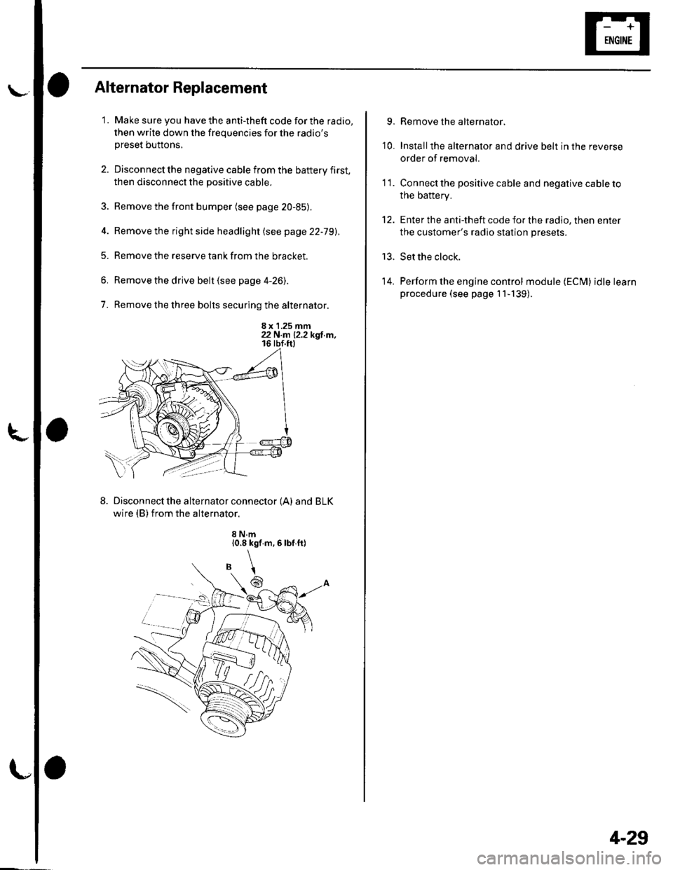
7. Remove the three bolts securing the alternator.
8 x 1.25 mm22 N.n 12.2 kgl.m,
Disconnect the alternator connector (A) and BLK
wire (B) from the alternator.
8 N.m10.8 kgf.m,6lbf.ft)
\
6
'I 1.
9.
10.
13.
14.
Remove the alternator.
Installthe alternator and drive belt in the reverse
order of removal.
Connect the positive cable and negative cable to
the battery.
Enter the anti-theft code for the radio, then enter
the customer's radio station presets.
Set the clock.
Perform the engine control module {ECM) idle learn
procedure (see page 11-139).
tt.
4-29
Page 66 of 1139
L
Special Tools Required. Driver 07749-0010000. Attachment,52 x 55 mm 07746-0010400
NOTE: Refer to the Exploded View as needed during
this procedure.
1, Test the alternator and regulator before you
remove them (see page 4-22l,.
2. Remove the alternator (see page 4-29).
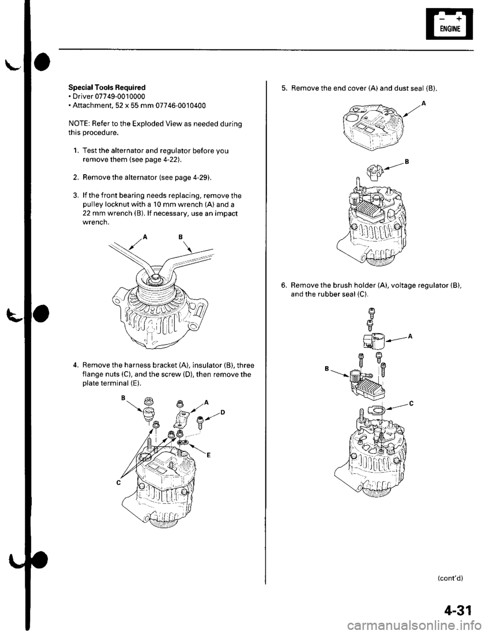
3. lf the front bearing needs replacing, remove thepulley locknut with a 10 mm wrench (A) and a
22 mm wrench (B). lf necessary, use an impact
wrencn.
Remove the harness bracket (A), insulator (B). three
flange nuts (C), and the screw (D), then remove theplate terminal (E).
,( ( , tt I;r_ lLt
5. Remove the end cover (A) anddustseal {B).
Remove the brush holder (A), voltage regulator (B),
and the rubber seal {C}.
6.
L1i.21---^
tqLJ
B-"--|.
(cont'd)
1!q[-dr,:l
4-31
Page 67 of 1139
Charging System
Alternator Overhaul (cont'dl
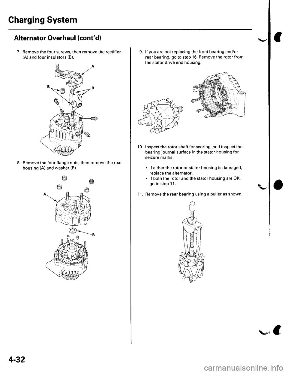
7. Remove the four screws, then remove the rectifier
(A) and four insulators (B).
Remove the four flange nuts, then remove the rear
housing (A) and washer (B).
o\
4-32
f.r,e
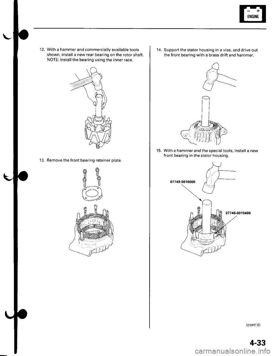
9. lf you are not replacing the front bearing and/or
rear bearing, go to step '16. Remove the rotor from
the stator drive end housing.
Inspect the rotor shaft for scoring, and inspect the
bearing journal surface in the stator housing for
setzure marks.
. lf eitherthe rotororstatorhousing isdamaged,
replace the alternator,. lf both the rotor and the stator housing are OK,
go to step 11.
'l 1. Remove the rear bearing using a puller as shown.
10.
\"
Page 68 of 1139
\-
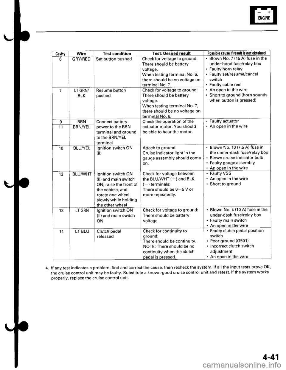
12. With a hammer and commercially available tools
shown, install a new rear bearing on the rotor shaft.
NOTE: Installthe bearing using the inner race.
13. Remove the front bearing retainer plate.
sqHE
6e
us
f-\
-:1s---'^/
14. Supportthe stator housing in a vise, and drive out
the front bearing with a brass drift and hammer.
15. With a hammer and the specialtools, install a new
front bearing in the stator housing.
07749-0010000
07746-0010400
(cont'd )
4-33
Page 76 of 1139
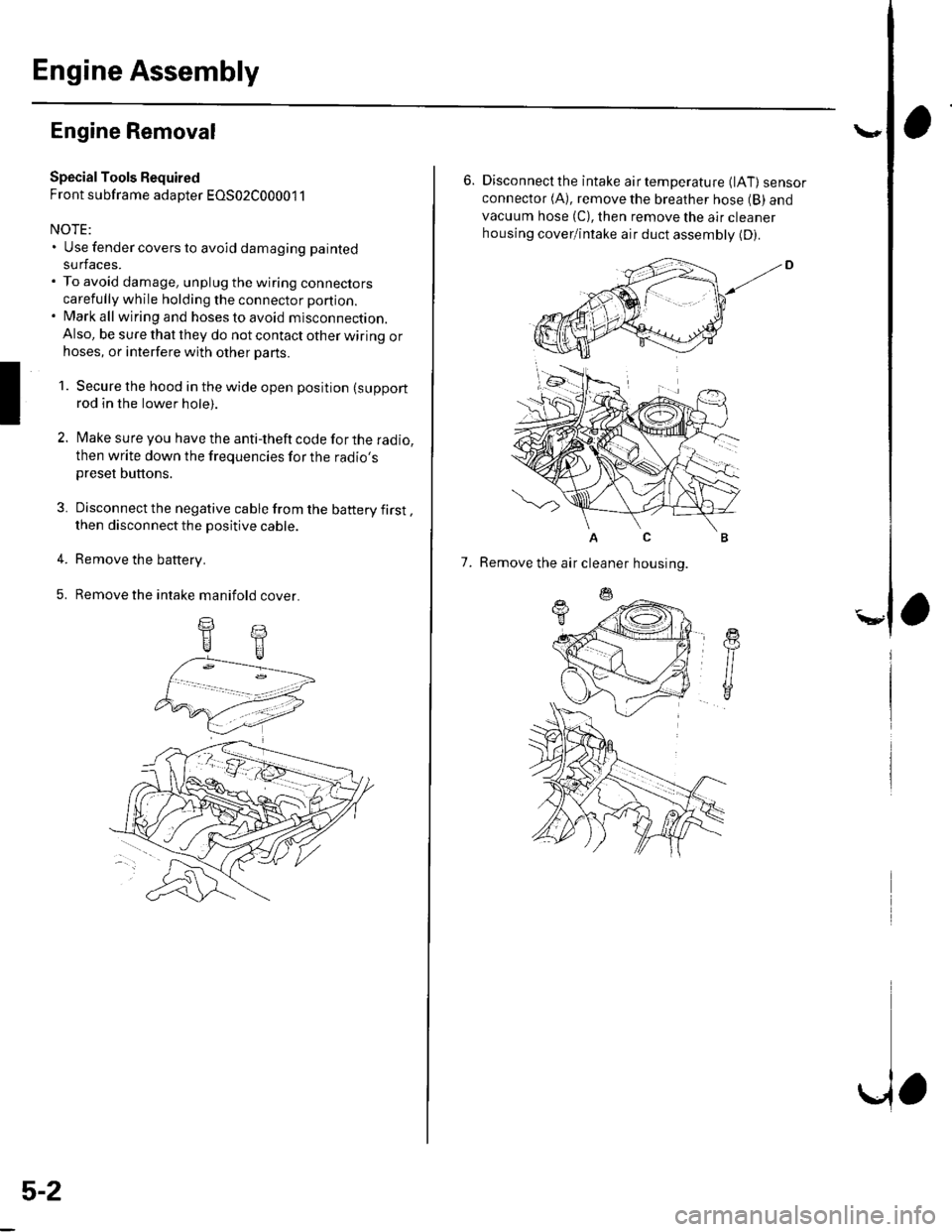
CavityWireTest conditionTest: Desired resultPossible cause il result is not obtained
6GRYiREDSet button pushedCheck for voltage to ground:
There should be battery
voltage,
When testing terminal No.6,
there should be no voltage on
terminal No. 7.
Blown No.7 (15 A)fuse in the
under-hood fuse/relay box
Faulty horn relay
Faulty sevresume/cancel
swrtch
Faulty cable reel
An open in the wire
Shon to ground (horn sounds
when button is pressed)
7LT GRN/
BLK
Resume button
pusneo
Check for voltage to ground:
There should be battery
voltage.
When testing terminal No.7,
there should be no voltage on
terminal No. 6.
BRNConnect battery
power to the BRN
terminal and ground
to the BRNIVEL
termrnal
Check the operation of the
actuator motor: You should
be able to hear the motor.
. Faulty actuator. An open in the wire11BRNI/EL
10B LUIVE Llgnition switch ON
0r)
Attach to groundi
Cruise indicator light in the
gauge assembly should come
on.
Blown No. 10 (7.5 A) fuse in
the under-dash fuse/relay box
Blown cruise indicator bulfl
Faulty gauge assembly
An open in the wire
12BLU/VVHTlgnition switch ON
(ll) and main switch
ON; raise the front of
the vehicle, and
rotate one wheel
slowly while holding
the other wheel
Check for voltage between
thE BLU/VVHT (+) ANd BLK
( )terminals:
Thereshouldbe0 5Vor
more repeatedly.
Faulty VSS
An open in the wire
Short to ground
13LT GRNlgnition switch oN
{ll) and main switch
ON
Check for voltage to ground:
There should be battery
voltage.
Blown No. 4 (10 A)fuse in the
under-dash fuse/relay box
Faulty main switch
An oDen in the wire
14LT BLUClutch pedal
reteaseo
Check for continuity to
grouno:
There should be continuity.
NOTE:There should be no
continuity when the clutch
oedal is Dressed.
Faulty clutch pedal position
swtlcn
Poor ground (G501)
Incorrect clutch switch
adjustment
An open in the wire
lf any test indicates a problem, find and correct the cause, then recheck the system. lf all the input tests prove OK,
the cruise control unit may be faulty. Substitute a known-good cruise control unit and retest. lf the system works
properly, replace the cruise control unit.
4-41
Page 82 of 1139
Engine Assembly
I
Engine Removal
Special Tools Required
Front subframe adapter EOS02C00001 1
NOTE:. Use fender covers to avoid damaging painted
surfaces.. To avoid damage, unplug the wiring connectors
carefully while holding the connector portion.. Mark all wiring and hoses to avoid misconnection.
Also, be sure that they do not contact other wiring orhoses, or interfere with other parts.
1. Secure the hood in the wide open position (support
rod in the lower hole).
2. Make sure you have the anti-theft code for the radio,
then write down the frequencies for the radio'spreset buttons.
3. Disconnect the negative cable from the battery first,then disconnect the positive cable.
4. Remove the battery.
5. Remove the intake manifold cover.
II
5-2
\,
6. Disconnectthe intake airtemperature (lAT) sensorconnector (A), remove the breather hose (B) and
vacuum hose (C), then remove the air cleaner
housing cover/intake air duct assemblv (D).
AC
7. Remove the air cleaner housing.
Page 85 of 1139
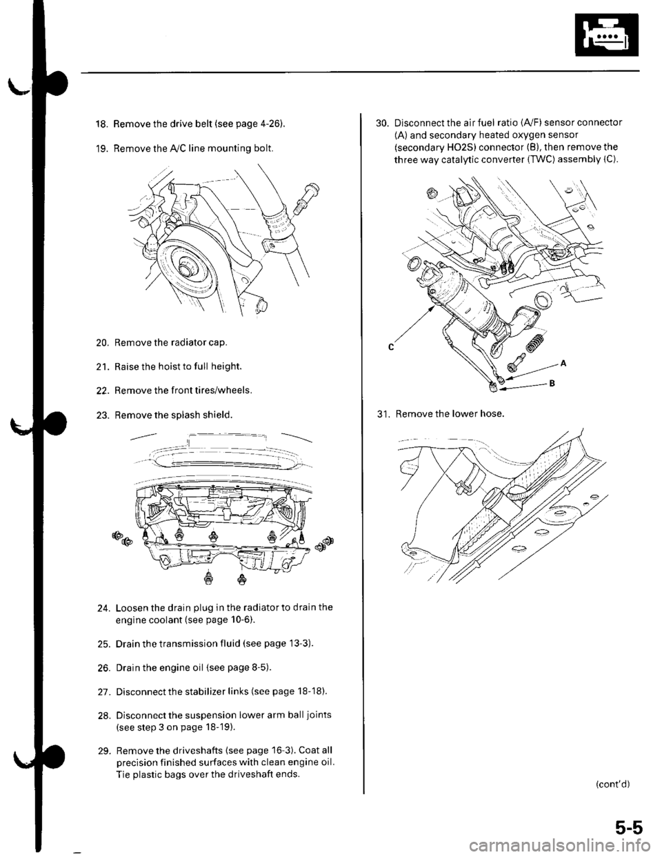
18.
19.
Remove the drive belt (see page 4-26).
Remove the lvC line mounting bolt.
20. Remove the radiator cap.
21. Raise the hoist to full height.
22. Remove the front tires/wheels.
23. Remove the splash shield.
o@
24. Loosen the drain plug in the radiatorto drain the
engine coolant (see page 10-6).
25. Drain the transmission fluid (see page 13'3).
26. Drain the engine oil {see page 8-5).
27. Disconnect the stabilizer links (see page 18-18).
28. Disconnect the suspension lower arm ball joints
(see step 3 on page 18-19).
29. Remove the driveshafts {see page 16-3). Coat all
precision finished surfaces with clean engine oil.
Tie plastic bags over the driveshaft ends.
30. Disconnect the air fuel ratio {4,/F) sensor connector
(A) and secondary heated oxygen sensor
(secondary HO2S) connector (B), then remove the
three way catalytic converter {TWC) assembly {C).
31. Remove the lower hose.
(cont'd)
5-5
Page 87 of 1139
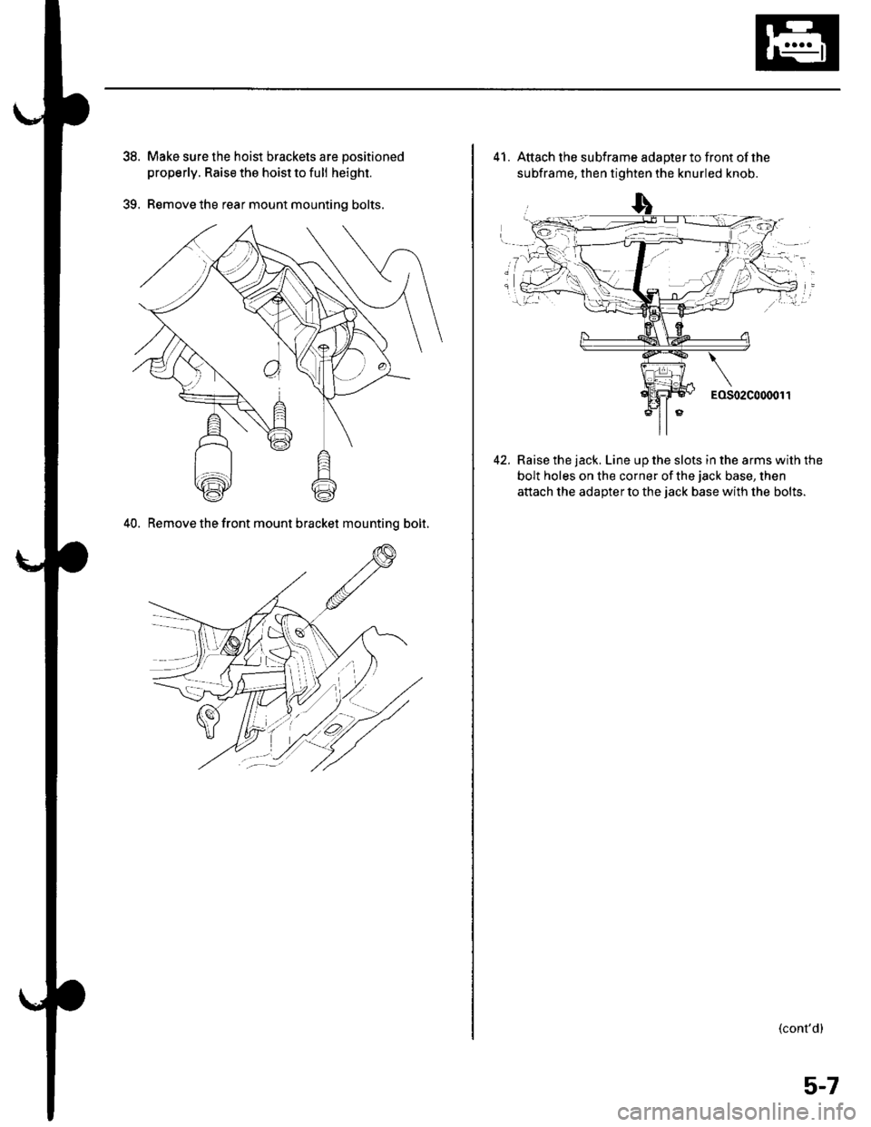
39.
Make sure the hoist brackets are positioned
properly. Raise the hoist to full height.
Remove the rear mount mounting bolts.
40. Remove the front mount bracket mountinq bolt.
41. Attach the subframe adapterto front ofthe
subframe, then tighten the knurled knob.
Raise the jack. Line up the slots in the arms with the
bolt holes on the corner of the jack base, then
attach the adaDter to the iack base with the bolts.
(cont'd)
5-7