Front HONDA CIVIC 2003 7.G Owner's Manual
[x] Cancel search | Manufacturer: HONDA, Model Year: 2003, Model line: CIVIC, Model: HONDA CIVIC 2003 7.GPages: 1139, PDF Size: 28.19 MB
Page 88 of 1139
Engine Assembly
Engine Removal (cont'd)
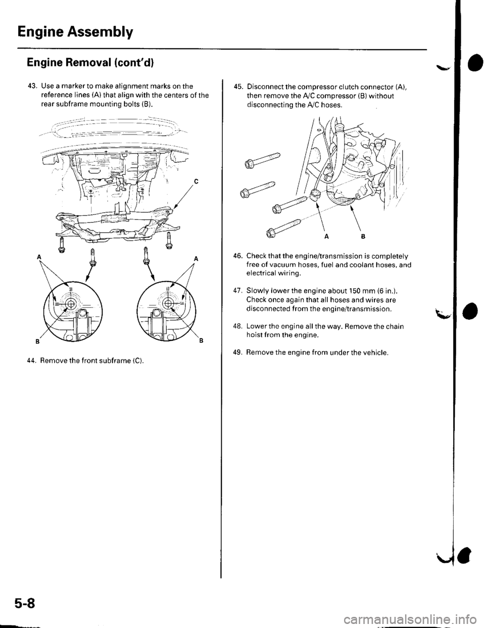
43. Use a marker to make alignment marks on the
reference lines (A) that align with the centers of the
rear subframe mounting bolts (B).
, !:_- _l.= :r -- ---.-','- -
44. Remove the front subframe (C).
5-8
ffi4
ffit'"
45. Disconnect the compressor clutch connector (A),
then remove the Ay'C compressor (B)without
disconnecting the A'./C hoses.
Check that the engine/transmission is completely
free of vacuum hoses, fuel and coolant hoses, and
electrical wiring.
Slowly lower the engine about 150 mm (6 in.).
Check once again that all hoses and wires are
disconnected trom the engine/transmission.
Lower the engine all the way. Remove the chain
hoist from the engine.
Remove the engine from under the vehicle.
46.
47.
48.
49.
Page 89 of 1139
Engine lnstallation
Special Tools Required
Front subframe adapter EOS02C00001 1
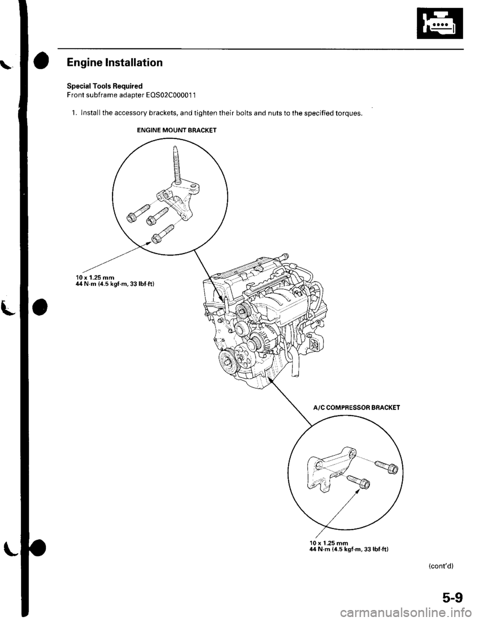
1. lnstallthe accessory brackets, and tighten their bolts and nuts to the specified torques.
10 x 1.25 mmil4 N.m {4.5 kgf.m,33lbl.ft)
A/C COMPRESSOR BRACKET
10 x 1 ,25 mm44 N.m {4.5 kgf.m,33lbt.ft)
(cont'dl
ENGINE MOUNT BRACKET
5-9
Page 91 of 1139
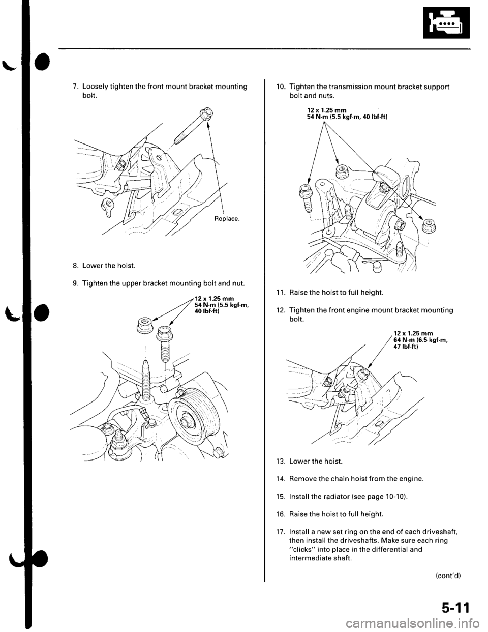
7. Loosely tighten the front mount bracket mounting
bolt.
Lower the hoist.
Tighten the upper bracket mounting bolt and nut.
8.
9.
10. Tighten the transmission mount bracket support
bolt and nuts.
12 x 1.25 mm54 N m {5.5 kgt m, 40 lbf.ft}
Raise the hoist to full height.
Tighten the front engine mount bracket mounting
bolt.
'l '1.
't2.
12 x 1.25 rnrn64 N.m {6.5 kgf.m,47 tbt.ftl
13. Lower the hoist.
14. Remove the chain hoist from the engine.
'15. Installthe radiator (see page 10-10).
'16. Raise the hoist to full height.
17. Install a new set ring on the end of each driveshaft,
then install the driveshafts. Make sure each ring"clicks" into place in the differential and
intermediate shaft.
(cont'd)
:l
5-11
Page 106 of 1139
10.
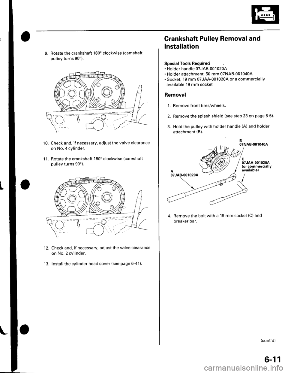
9. Rotate the crankshaft 180" clockwise (camshaft
pullev turns 90').
Check and, if necessary, adjust the valve clearance
on No.4 cylinder.
Rotate the crankshaft 180" clockwise (camshaft
pulley turns 90").
Check and, if necessary, adjust the valve clearance
on No. 2 cylinder.
Install the cylinder head cover (see page 6-41).
11.
12.
Crankshaft Pulley Removal and
Installation
Special Tools Required. Holder handle 07JAB-001020A. Holder attachment, 50 mm 07NAB-001040A. Socket, 19 mm 07JAA-001020,4 or a commercially
available 19 mm socket
Removal
1. Remove front tires/wheels.
2. Remove the splash shield (see step 23 on page 5-5).
3. Hold the pulley with holder handle (A) andholder
attachment (B).
B07NAB-001040A
el
/ Srroo.oo,oroo/ (or commercially
f available)
/
Remove the bolt with a 19 mm socket (C) and
breaker bar.
(cont'd)
6-11
Page 107 of 1139
Cylinder Head
Crankshaft Pulley Removal and
Installation (cont'dl
Installation
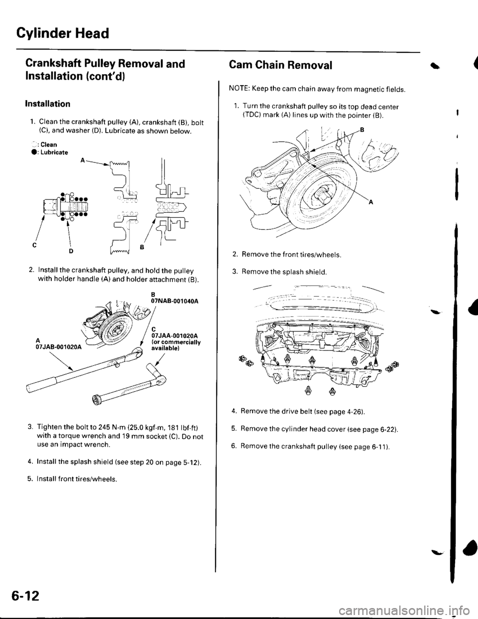
1. Clean the crankshaft pulley (A), crankshaft (B), bolt(C). and washer (D). Lubricate as shown below.
. .: Clean
O; Lubricate
Installthe crankshaft pulley, and hold the pulley
with holder handle (A) and holder attachment {B).
B07NAB-0010iroA
A07JAB-001020A
Tighten the bolt to 245 N.m (25.0 kgf.m, 181 tbf.ft)with a torque wrench and 19 mm socket (C). Do notuse an impact wrench.
Install the splash shield (see step 20 on page 5-12).
Insta ll front tires/wh eels.
ll
ll
t[] rL-'....-----=a
(-, ,
5U-1JItt-
5.
6-12
\-
Cam Chain Removal
NOTE: Keep the cam chain away from magnetic fields.
1. Turn the crankshaft pulley so ils top dead center(TDC) mark (A) lines up with the poinrer (B).
Remove the front tires/wheels.
Remove the splash shield.
a
2.
3.
-,,--.=.-----__--_
4. Remove the drive belt (see page 4-26).
5. Remove the cylinder head cover (see page 6-22).
6. Remove the crankshaft pulley (see page 6-11).
\
Page 149 of 1139
1.
OilPan Removal
Drain the engine oil (see page 8-5).
lf the engine is still in the vehicle, remove the
subframe.
-1 Attach the chain hoist to the engine (see step
35 on page 5-6).-2 Disconnectthe suspension lower arm balljoints (see step 3 on page 18-19).-3 Remove the rear mounl mounting bolts (see
step 39 on page 5-7).-4 Remove the front mount mounting bolt (see
step 40 on page 5-7).-5 Use a marker to make alignment marks on the
reference lines that align with the centers of
the rear subframe mounting bolts. Remove the
front subframe (see step 43 on page 5-8).
Remove the bolts/nuts securing the oil pan.
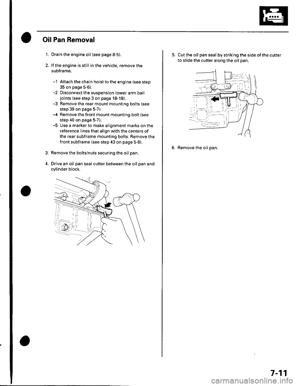
Drive an oil pan seal cutter between the oil pan and
cylinder block.
5. Cut the oil panseal bystrikingthesideofthecutter
to slide the cutter along the oil pan.
6. Remove the oil pan.
7-11
Page 166 of 1139
Engine Block
Oil Pan Installation (cont'dl
6. lf the engine is still in the vehicle, install the
subframe,
-1 Installthe subframe. Align the reference lines
on the subframe with the bolt head center, then
tighten the bolts (see step 5 on page 5-10).-2 Tighten the front mounting bolt (see step 6 onpage 5-10).-3 Tighten the rear mount mounting bolts (see
step 7 on page 5-11).-4 Connect the suspension lower arm ball joints
(see step 6 on page 18-19).
7. After assembly, wait at least 30 minutes before
filling the engine with oil.
7-28
v
Transmission End Grankshaft Seal
Installation - In Car
Special Tools Required. Driver 07749-0010000. Oil seal driver attach ment 96 07ZAD-PNAA100
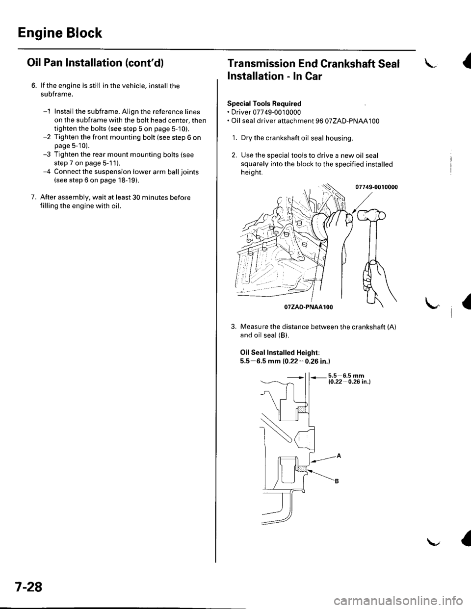
'1. Dry the crankshaft oil seal housing.
2. Use the special tools to drive a new oil seal
squarely into the block to the specified installed
height.
07749-0010000
and oil seal (B).
Oil Seal Installed Height:
5.5 6.5 mm 10.22-0.26 in.l
5.5 6.5 mml0.22- O.26 in .l
I
/$rRfr4T
tr*W(r
-]t
fl\OTZAD.PNAAlOO
Measure the distance between the crankshaft (A)
a
Page 174 of 1139
Engine Lubrication
OilPump Overhaul
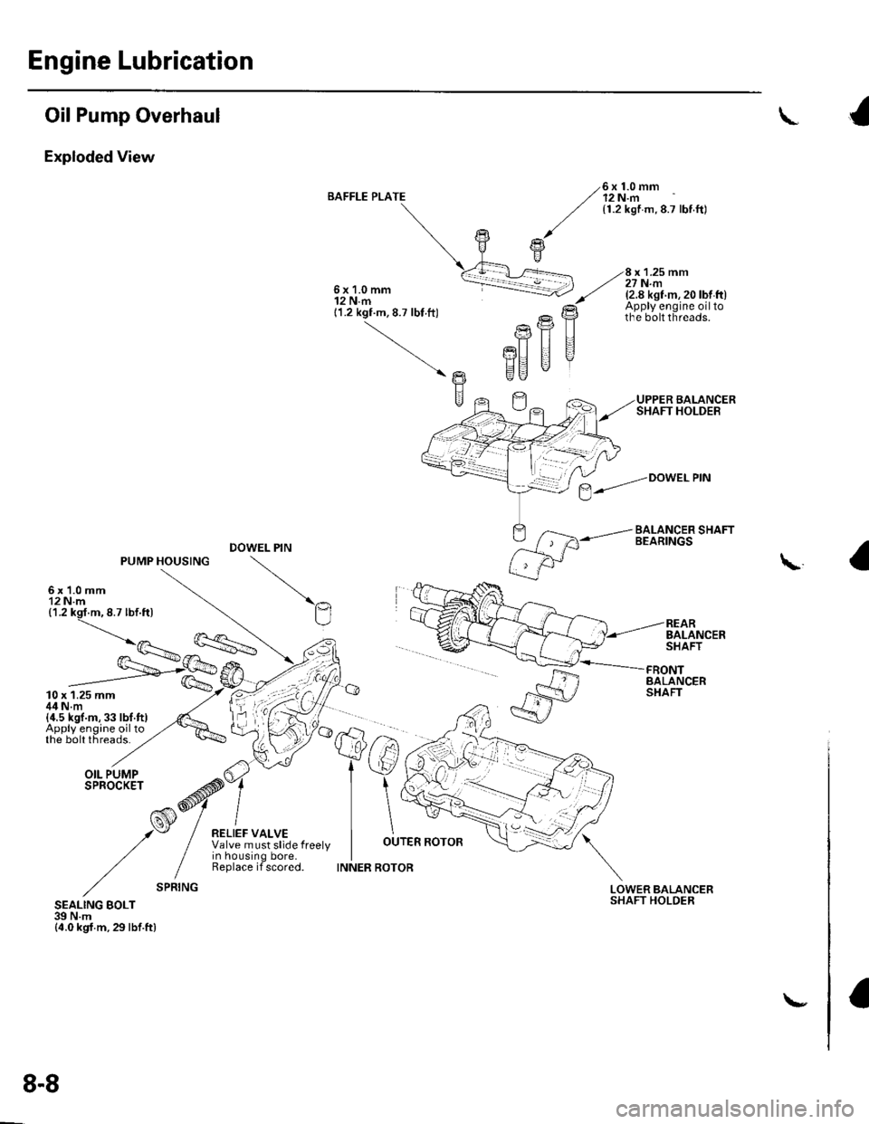
Exploded View
BAFFLE PLATE6x1.0mm12 N.m{1.2 kgf m,8.7 lbf.ft)
x 1.25 mm27 N.m6x1.0mm12 N.m11.2 kgf.m, 8.7 lbt ft)
(2.8 kst m, 20 lbt ft)Apply engine oiltothe bolt threads.
UPPER BALANCERSHAFT HOLDER
BALANCER SHAFTBEARINGS
Ptr
PU II
EU "
DOWEL PIN
REARBALANCERSHAFT
\
- /=.---'n
fs/
tw
FRONTBALANCERSHAFT
LOWERSHAFTBALANCERHOLDERSEALING BOLT39 N.m{4.0 kgf.m,29lbf.ftl
$--."Dowetem
8-8
\-
Page 177 of 1139
1.
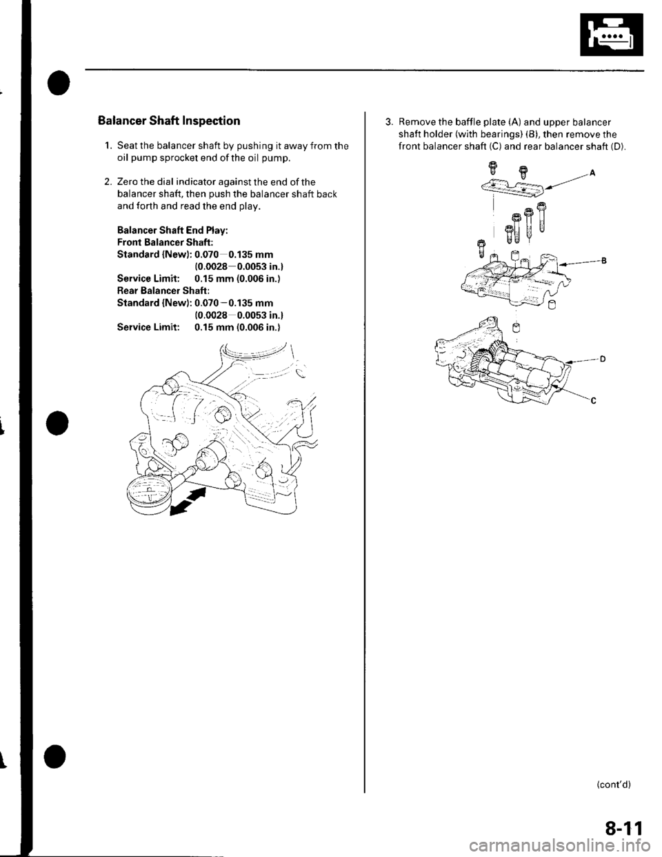
Balancer Shaft Inspection
Seat the balancer shaft by pushing it away from the
oil pump sprocket end ofthe oil pump.
Zero the dial indicator against the end of the
balancer shaft, then push the balancer shaft back
and forth and read the end olav.
Balancer Shaft End Play:
Fronl Balancer Shaft:
Standard {Newl: 0.070 0.135 mm
{0.0028 0.0053 in.}
Service Limit: 0.15 mm (0.006 in.)
Rear Balancer Shaft:
Standard {New): 0.070-0.135 mm(0.0028 0.0053 in.l
Service Limit: 0.15 mm (0.006 in.)
2.
3. Remove the baffle plate (A) and upper balancer
shaft holder {with bearings) (B), then remove the
front balancer shaft (C) and rear balancer shaft (D).
9H.A''/.r L=] j/
R
Rfl|]
3I] UUr Be
+-
(cont'd)
8-11
Page 178 of 1139
Engine Lubrication
Oil Pump Overhaul (cont'dl
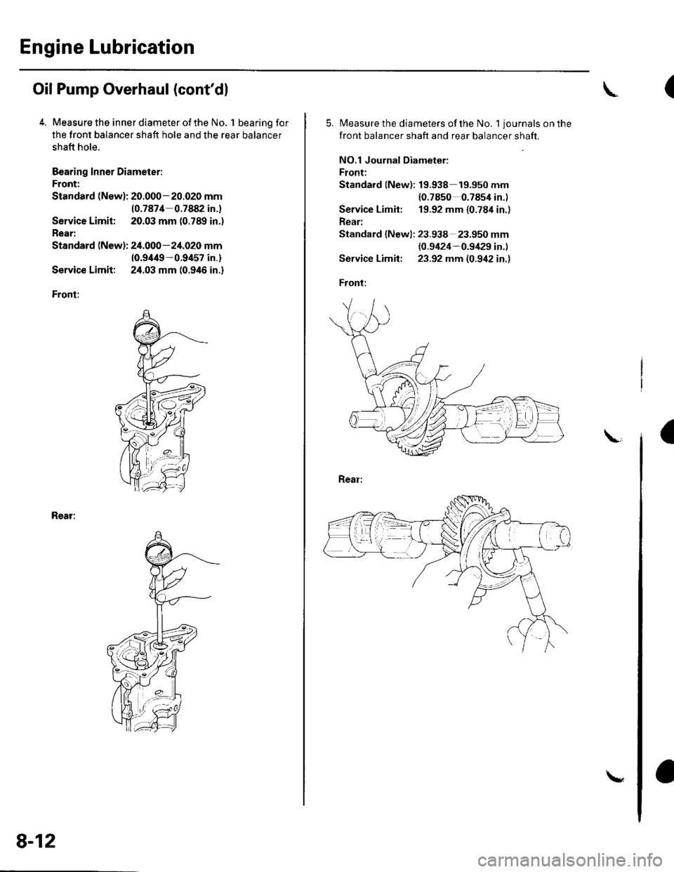
4. Measure the inner diameter of the No. 1 bearing for
the front balancer shaft hole and the rear balancer
shaft hole.
Bearing Inner Diameier:
Front:
Standard (New): 20.000-20.020 mm(0.7874 0.7882 in.)
Service Limit; 20.03 mm (0.789 in.)
Rear:
Standard (New): 24.000-24.020 mm
10.9/t49-0.9457 in.)
Service Limit: 24.03 mm (0.946 in.)
Front:
Rear:
8-12
\
(
5.Measure the diameters of the No. 1 journals on the
front balancer shaft and rear balancer shaft.
NO.1 Journal Diameter:
Front:
Standard lNew): 19.938 19.950 mm(0.7850 0.7854 in.)
Service Limit: 19.92 mm {0.784 in.)
Rear:
Standard lNewl: 23.938 23.950 mm
{0.9424-0.9/129 in.)
Service Limit: 23.92 mm (0.942 in.)
Front:
a