Front HONDA CIVIC 2003 7.G Repair Manual
[x] Cancel search | Manufacturer: HONDA, Model Year: 2003, Model line: CIVIC, Model: HONDA CIVIC 2003 7.GPages: 1139, PDF Size: 28.19 MB
Page 512 of 1139
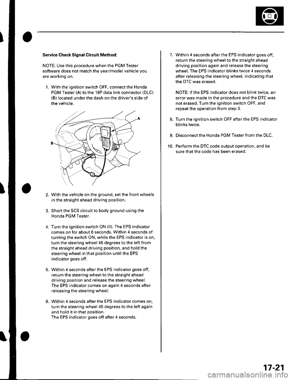
Service Check Signal Circuit Method:
NOTE: Use this procedure when the PGM Tester
software does not match the yearlmodel vehicle you
are working on.
1. With the ignition switch OFF, connect the Honda
PGM Tester (A) to the 16P data link connector {DLC)(B) located under the dash on the driver's side of
the vehicle.
With the vehicle on the ground, set the front wheels
in the straight ahead driving position.
Short the SCS circuit to body ground using the
Honda PGM Tester.
Turn the ignition switch ON (ll). The EPS indicator
comes on for about 6 seconds. Within 4 seconds of
turning the switch ON, while the EPS indicator is on,
turn the steering wheel 45 degrees to the left from
the straight ahead driving position, and hold the
steering wheel in that position until the EPS
indicator goes off.
Within 4 seconds afterthe EPS indicator goes off,
return the steering wheel to the straight ahead
driving position and release the steering wheel.
The EPS indicator comes on again 4 seconds after
releasing the steering wheel,
Within 4 seconds after the EPS indicator comes on,
turn the steering wheel 45 degrees to the left again
and hold it in that position.
The EPS indicator goes off after 4 seconds.
4.
1.Within 4 seconds after the EPS indicator goes off,
return the steering wheel to the straight ahead
driving position again and release the steering
wheel. The EPS indicator blinks twice 4 seconds
after releasing the steering wheel, indicating that
the DTC was erased.
NOTE: If the EPS indicator does not blink twice, an
error was made in the procedure and the DTC was
not erased. Turn the ignition switch OFF, and
repeat the operation from step 3.
Turn the ignition switch OFF afterthe EPS indicator
blinks twice.
9. Disconnect the Honda PGM Tester from the DLC.
10. Perform the DTC code output operation, and be
sure that the code has been erased.
17-21
Page 524 of 1139
DTC 22: Vehicle Speed Sensor Signal
DTC 23: Engine Speed Signal
NOTE:. lf the MIL indicator is ON, troubleshoot the PGIVI-Fl
system first.. Even though the system is operating normally, the
EPS indicator will come on under the following
conditions.
- Condition 1:. The vehicle was traveling at least '12.4 mph(20 km/h), then. A rapld change in vehicle speed was detected,
then. The vehicle (or the vehicle speed sensor signal)
stopped for at least 5 seconds, and. The engine speed was still 1,640 rpm or higher for
at least 5 seconds- Condition 2:
After the vehicle (or the vehicle speed sensor
signal) has stopped for at least 10 seconds, yetthe
engine speed was still 1,640 rpm or higher for at
least 20 seconds.- Condition 3:
When the vehicle speed is 10 km/h (6.2 mph) or
above and the engine is running at 280 rpm or
below for 3 seconds.
1. Start the engine and check the tachometer.
ls the tachometer working correctly?
YES- Go to step 2.
NO-Go to step 9.
2. Test-drive the vehicle above 15 km/h {9.3 mph).
ls the speedometer working correctly?
YES Go to step 3.
NO-Perform the speedometer system
troubleshooting {see page 22-651.a
3.Block the rear wheels and raise the vehicle, and
make sure it is securely supported.
Turn the ignition switch ON (ll).
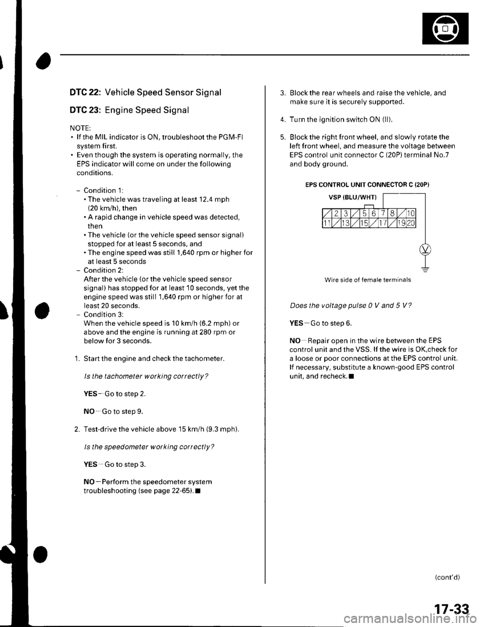
Block the right front wheel, and slowly rotate the
left front wheel, and measure the voltage between
EPS control unit connector C (20P)terminal No.7
and body ground.
EPS CONTROL UNIT CONNECTOR C {2OP)
Does the voltage pulse 0 V and 5 V?
YES Go to step 6.
NO Repair open in the wire between the EPS
control unit and the VSS. lf the wire is OK,check for
a loose or poor connections at the EPS control unit.
lf necessary, substitute a known-good EPS control
unit, and recheck.l
(conr'd)
4.
5.
Wire side of female terminals
17-33
Page 542 of 1139
Steering Gearbox Removal
Special Tool Required
Ball ioint remover,2S mm 0TlvlAC-S100200
1. Raise the front of vehicle, and make sure it is
securely supponed.
2. Remove the front wheels.
Remove the driver's airbag (seepage23-113).
Remove the steering wheel (see page 17-6).
Remove the motor on the steering gearbox (see
page l T-49).
Remove the driver's dashboard lower cover (see
page 20-59) and under cover {see page20-60).
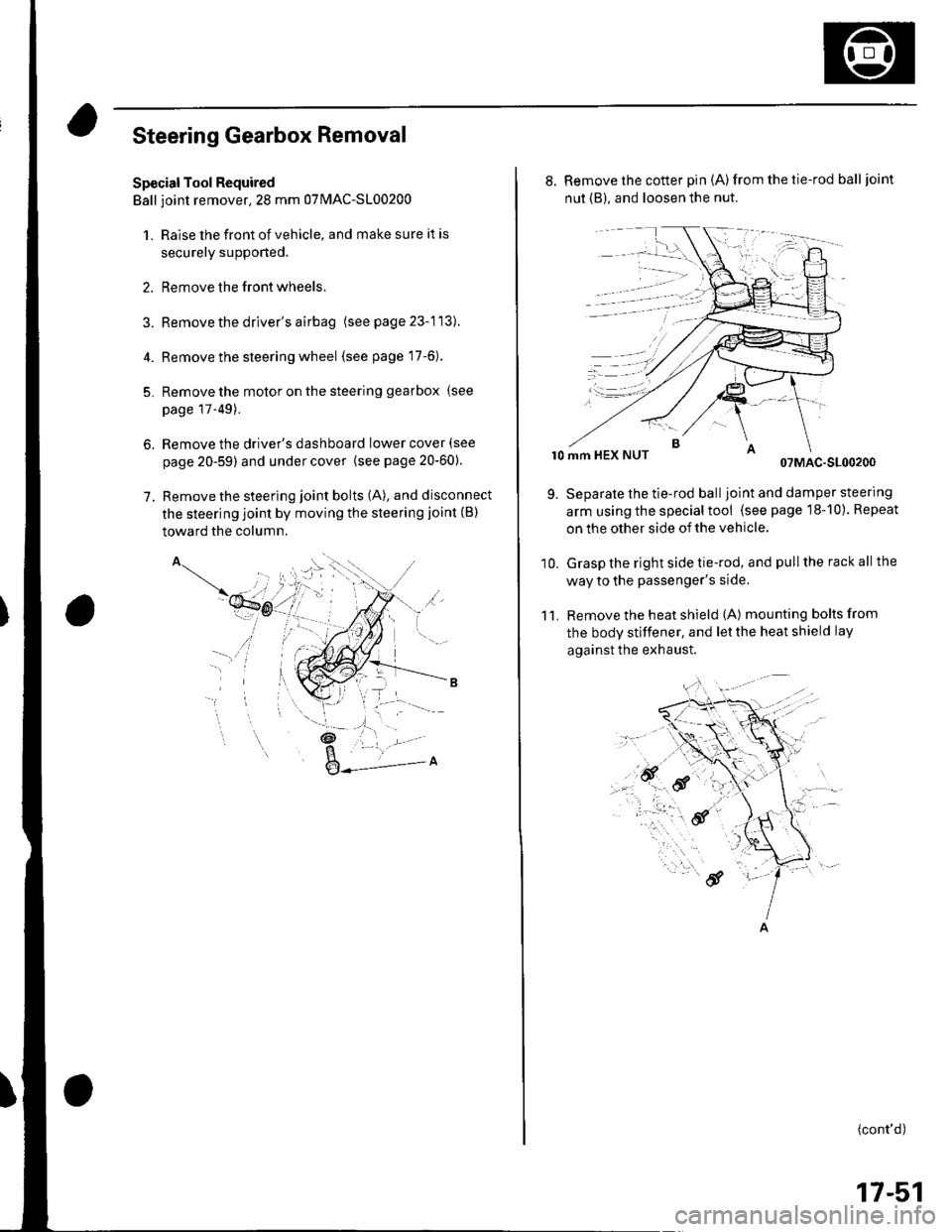
Remove the steering joint bolts (A), and disconnect
the steering joint by moving the steering joint (B)
toward the column.
4.
5.
6.
7.
'il
_t\
l- '/
,a.: --L -
8. Remove the cotter pin (A)from the tie-rod balljoint
nut {B), and loosen the nut.
r0 mm HEX NUT07MAC-S100200
Separate the tie-rod balljoint and damper steering
arm using the special tool (see page 18-10). Repeat
on the other side of the vehicle.
Grasp the right side tie-rod, and pull the rack all the
way to the passenger's side,
Remove the heat shield (A) mounting bolts from
the body stiffener, and let the heat shield lay
against the exhaust.
11.
9.
10.
(cont'd)
17-51
Page 557 of 1139
EPS Components
4
17.
18.
Steering Gearbox Installation (cont'dl
Install the motor on the steering gearbox (see page
17-49).
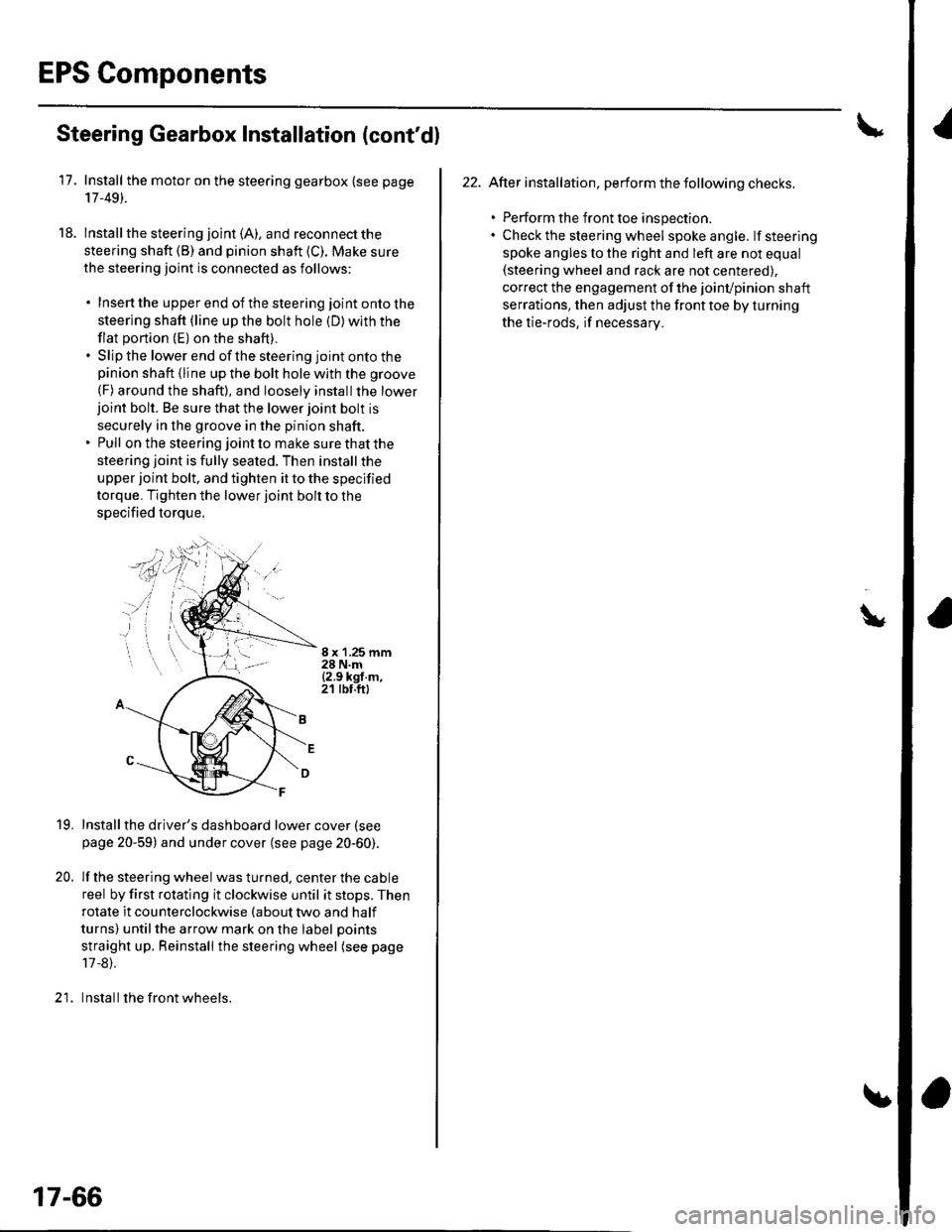
lnstall the steering joint (A). and reconnect the
steering shaft (B) and pinion shaft (C). Make sure
the steering joint is connected as follows:
. Insertthe upperend of thesteering jointontothe
steering shaft (line up the bolt hole (D) with the
flat portion (E) on the shaft).. Slip the lower end of the steering joint onto thepinion shaft (line up the bolt hole with the groove
(F) around the shaft), and loosely installthe lowerjoint bolt. Be sure that the lower joint bolt is
securely in the groove in the pinion shaft.. Pull on the steering joint to make sure that the
steering joint is fully seated. Then install the
upper joint bolt, and tighten it to the specified
torque. Tighten the lower joint bolt to the
specified torque.
8 x '1.25 mm28 N.m{2.9 kgf.m,21 tbt.ft)
19.
20.
Installthe driver's dashboard lower cover (see
page 20-59) and under cover (see page 20-60).
lf the steering wheel was turned, center the cable
reel by first rotating it clockwise until it stops. Then
rotate it counterclockwise (about two and half
turns) untilthe arrow mark on the label points
straight up. Reinstall the steering wheel (see page
17 -8).
Install the front wheels.)1
17-66
22. After installation, perform the following checks.
. Perform the front toe inspection.. Check the steering wheel spokeangle. lfsteering
spoke angles to the right and left are not equal(steering wheel and rack are not centered),
correct the engagement of the joinvpinion shaft
serrations, then adjust the front toe by turning
the tie-rods, if necessarv.
\
Page 559 of 1139
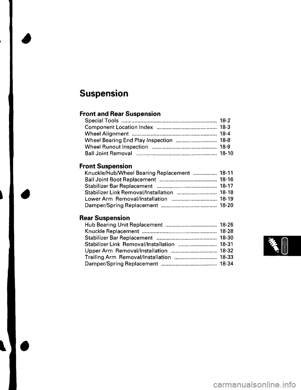
Suspension
Front and Rear Suspension
SpecialTools ............. 18-2
Component Location Index ......................................... 18-3
Wheel Alignment ..................... ........... 18-4
Wheel Bearing End Play Inspection ............................ 18-8
Wheel Runout Inspection .................. 18-9
Ball Joint Removal ... 18-10
Front Suspension
Kn uckle/H u bAVheel Bearing Replacement
Ball Joint Boot Reolacement ..................
Stabilizer Bar Rep|acement ....................
Stabilizer Link Removal/lnstallation
LowerArm Removal/lnstallation ...............
Damper/Spring Replacement
Rear Suspension
Hub Bearing Unit Replacement .....................
Knuckle Reolacement
Stabilizer Bar Replacement ....................
Stabilizer Link Removal/lnstallation ..........................
Upper Arm Removal/lnstallation ...............
Trailing Arm Removal/lnstallation
Damper/Spring Replacement
18-1 1
18-16
18-17
18-18
18-19
18-20
18-26
18-28
18-30
18-31
18-32
18-33
18-34
Page 560 of 1139
![HONDA CIVIC 2003 7.G Repair Manual Front and Rear Suspension
SpecialTools
o
[]
o
o
a6,l@
I
Ref.No.Tool NumberDescriptionotv
o
@
o
G)
07GAF-SE00100
07MAC-S100200
07746-0010500
07749-0010000
07965-SA50500
07965-SD90100
Hub Dis/Assembly T HONDA CIVIC 2003 7.G Repair Manual Front and Rear Suspension
SpecialTools
o
[]
o
o
a6,l@
I
Ref.No.Tool NumberDescriptionotv
o
@
o
G)
07GAF-SE00100
07MAC-S100200
07746-0010500
07749-0010000
07965-SA50500
07965-SD90100
Hub Dis/Assembly T](/img/13/5744/w960_5744-559.png)
Front and Rear Suspension
SpecialTools
o
[]
o
o
a6,l@
I
Ref.No.Tool NumberDescriptionotv
o
@
o
G)
07GAF-SE00100
07MAC-S100200
07746-0010500
07749-0010000
07965-SA50500
07965-SD90100
Hub Dis/Assembly Tool
Ball Joint Remover, 28 mm
Attachment, 62 x 68 mm
Driver
Front Hub Dis/Assembly Tool
Support Base
18-2
Page 561 of 1139
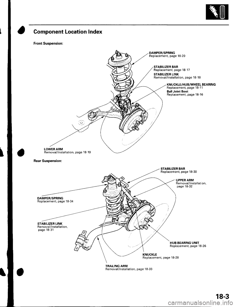
Component Location Index
Front Suspension:
LOWEB ARMRemoval/lnstallation, page 18 19
Rear Suspension:
DAMPER/SPRINGReplacement, page'18-34
DAMPER/SPRINGReplacement, page 18-20
STABILIZER BARReplacement, page 18-17
STABILIZER LINKRemoval/lnstallation, page 18 18
STABILIZER BARReplacement. page 18-30
KNUCKLE/HU8/WHEEL BEARINGReplacement, page 18-1 1
Ball Joint BootReplacement, page'18-16
UPPER ARMRemoval/lnstallation,page'18-32
HUB BEARING UNITReplacement, page 18'26
KNUCKLEReplacement, page 18-28
TRAILING ARMRemoval/lnstallation, page 18 33
18-3
Page 562 of 1139
Front and Rear Suspension
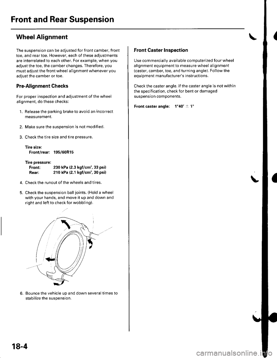
WheelAlignment
The suspension can be adjusted for front camber, front
toe, and rear toe. However, each of these adjustments
are interrelated to each other. For example, when you
adjust the toe, the camber changes. Therefore, you
must adjust the front wheel alignment whenever you
adjust the camber or toe.
Pre-Alignment Checks
For proper inspection and adjustment of the wheel
alignment, do these checks:
1. Release the parking brake to avoid an incorrect
measurement.
Make sure the suspension is not modified.
Check the tire size and tire pressure
Tire size:
Front/rear: 195/60R15
Tire pressure:
Front: 230 kPa {2.3 kgf/cm',33 psil
Rear: 210 kPa |'2.1 kgf/cm', 30 psi)
Check the runout of the wheels and tires.
Check the suspension ball joints. (Hold a wheel
with your hands, and move it up and down and
right and left to check for wobbling),
2.
3.
Bounce the vehicle up and down several times to
stabilize the suspension.
18-4
Front Caster lnspection
Use commerciallv available comDuterized four wheel
alignment equipment to measure wheel alignment
(caster, camber, toe, and turning angle). Follow the
eouioment manufacturer's instructions.
Check the caster angle. lf the caster angle is not within
the specification, check for bent or damaged
susoensron comoonents.
Front caster angle: 1'40't 1"
\
Page 563 of 1139
Front Camber Inspection
Use commercially available computerized four wheel
alignment equipment to measure wheel alignment(caster, camber, toe, and turning angle). Follow the
equipment manufacturer's instructions.
Check the camber angle. lf the camber angle is not
within the specification, adjust the camber.
Front camber angle: 0"30' t 45'
Front Camber Adjustment
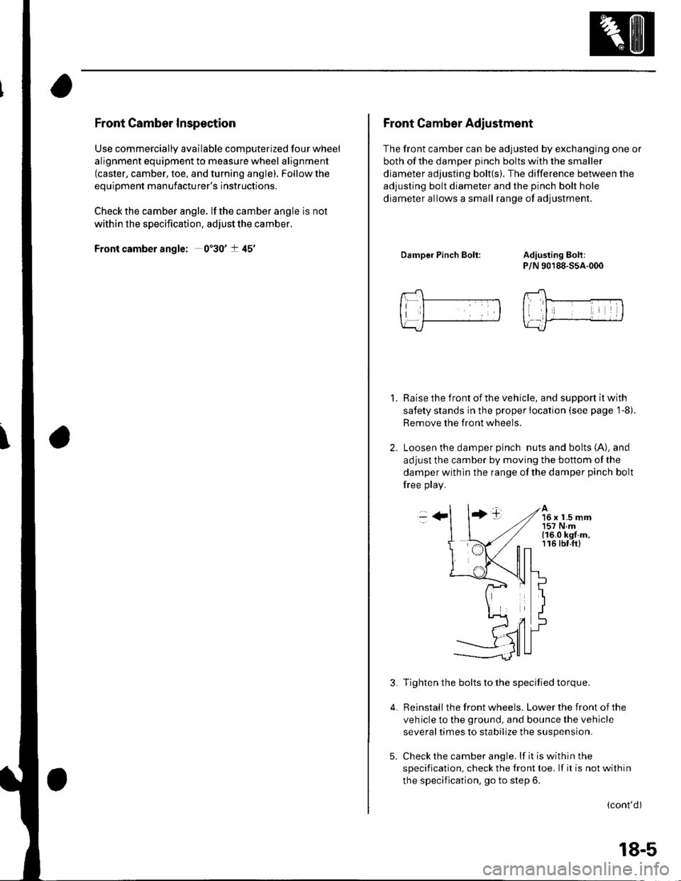
The front camber can be adjusted by exchanging one or
both of the damDer Dinch bolts with the smaller
diameter adjusting bolt(s). The difference between the
adjusting bolt diameter and the pinch bolt hole
diameter allows a small range of adjustment.
DamDer Pinch Bolt:Adiusting Boh:
P/N 90188-55A-000
Raise the front of the vehicle, and support it with
safety stands in the proper location (see page 1-8).
Remove the front wheels.
Loosen the damper pinch nuts and bolts (A), and
adjust the camber by moving the bottom of the
damper within the range of the damper pinch bolt
free play.
1.
-++tA16 x 1.5 mm157 N.m(16.0 kgf.m,116 tbf.ftl
3.
4.
Tighten the bolts to the specified torque.
Reinstall the front wheels. Lower the front of the
veh icle to the ground, and bounce the vehicle
several times to stabilize the suspension.
Check the camber angle. lf it is within the
specification, check the front toe. lf it is not within
the specification, go to step 6.
(cont'dl
5.
18-5
Page 564 of 1139
Front and Rear Suspension
Wheel Alignment (cont'd)
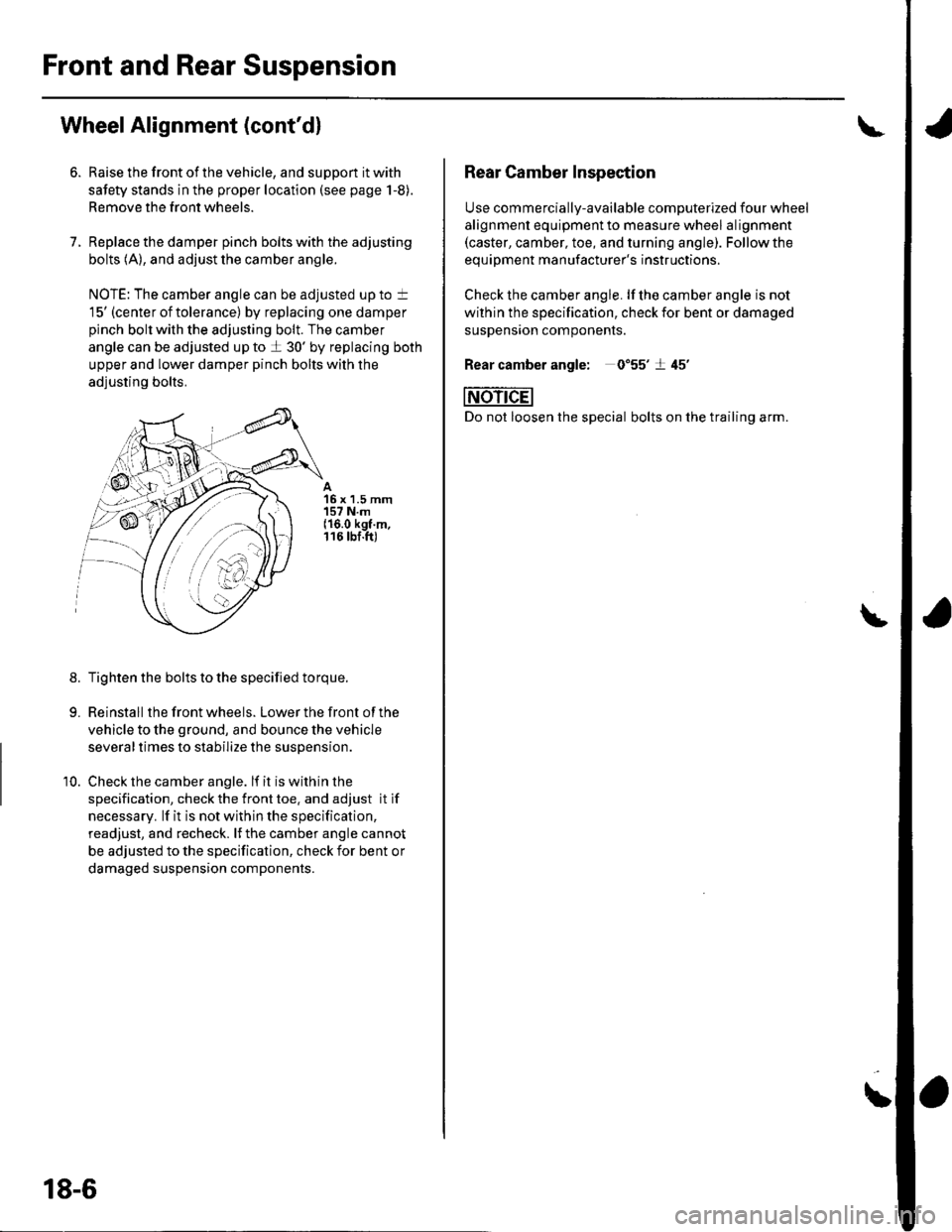
7.
Raise the front of the vehicle, and support it with
safety stands in the proper location (see page 1-8).
Remove the front wheels.
Replace the damper pinch bolts with the adjusting
bolts (A), and adjust the camber angle.
NOTE: The camber angle can be adjusted up to t
15' (center of tolerance) by replacing one damper
pinch bolt with the adjusting bolt. The camber
angle can be adjusted up to a 30' by replacing both
upper and lower damper pinch bolts with the
adjusting bolts.
15 x 1.5 mm157 N.m{16.0 kgt.m,116 tbf.ft)
8.Tighten the bolts to the specified torque.
Reinstall the front wheels. Lower the front of the
vehicle to the ground, and bounce the vehicle
several times to stabilize the suspension.
Check the camber angle. lf it is within the
specification, check the front toe. and adjust it if
necessary. lf it is not within the specification,
readjust, and recheck. lJ the camber angle cannot
be adjusted to the specification, check for bent or
damaged suspension components.
10.
'rntr
i,iY. a
.:r,//
18-6
Rear Camber Inspection
Use commercially-available computerized four wheel
alignment equipment to measure wheel alignment(caster, camber, toe, and turning angle). Follow the
eouiDment manufacturer's instructions.
Check the camber angle. lf lhe camber angle is not
within the specification, check for bent or damaged
susDenston comoonenrs.
0"55'�t 45'�
bolts on the trailing arm.
Rear camber angle: 0
NOn-dEl
Do not loosen the special
\