Front HONDA CIVIC 2003 7.G Service Manual
[x] Cancel search | Manufacturer: HONDA, Model Year: 2003, Model line: CIVIC, Model: HONDA CIVIC 2003 7.GPages: 1139, PDF Size: 28.19 MB
Page 421 of 1139
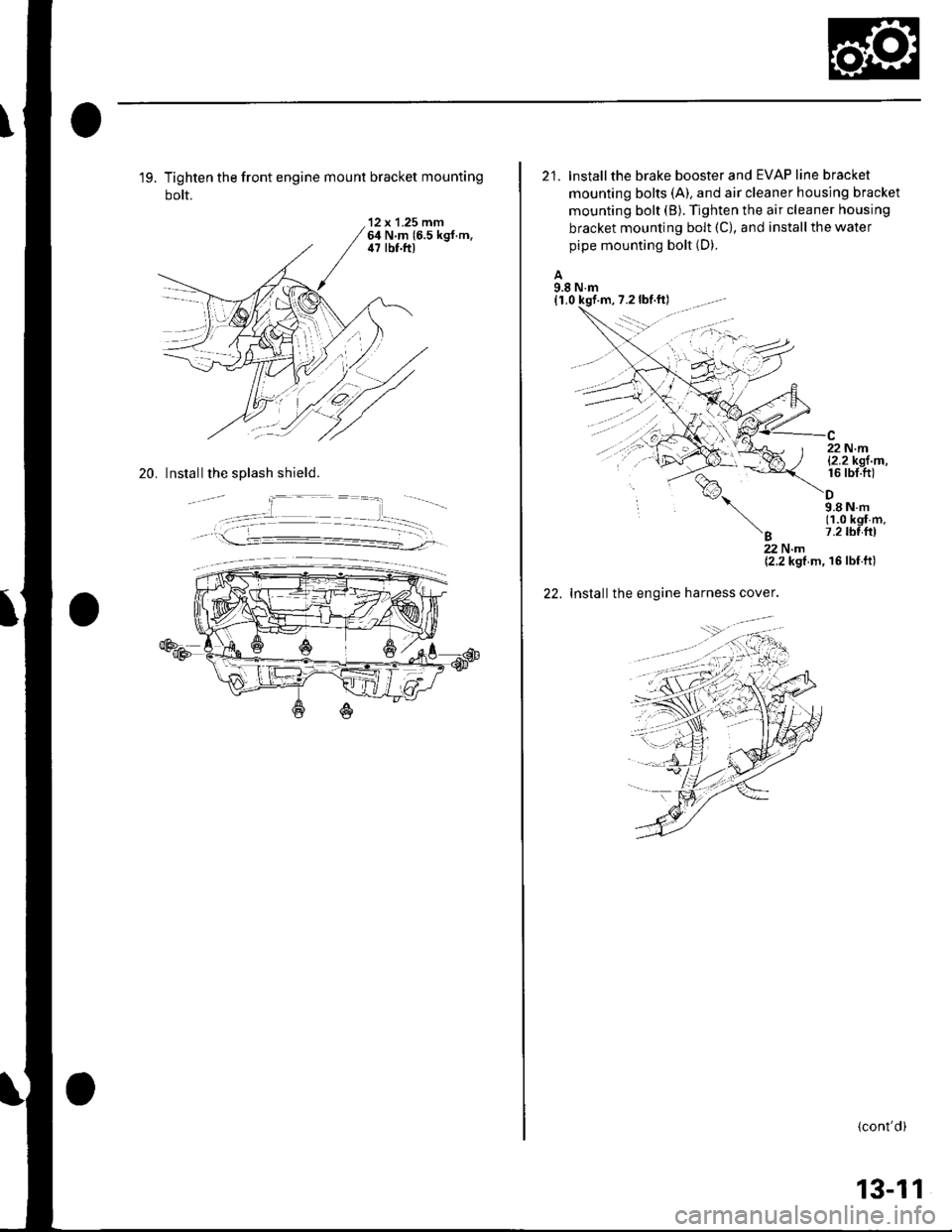
19. Tighten the front engine mount bracket mounting
bolt.
'12 x 1.25 mm64 N.m 16.5 kgf.m,il7 lbf.ft)
20. Install the splash shield.
21. lnstallthe brake booster and EVAP line bracket
mounting bolts (A). and air cleaner housing bracket
mounting bolt (B). Tighten the air cleaner housing
bracket mounting bolt (C), and install the water
pipe mounting bolt (D).
A9.8 N.m(1,0 kqf
%,
'B
22 N.ml2.2kgl m,16 rbt.ft)
9.8Nm(1.0 kgf m.7.2 tbl{rl
22.
22Nm{2.2 kgf m, 16 lbf ft)
Installthe engine harness cover.
(cont'd)
13-11
Page 423 of 1139
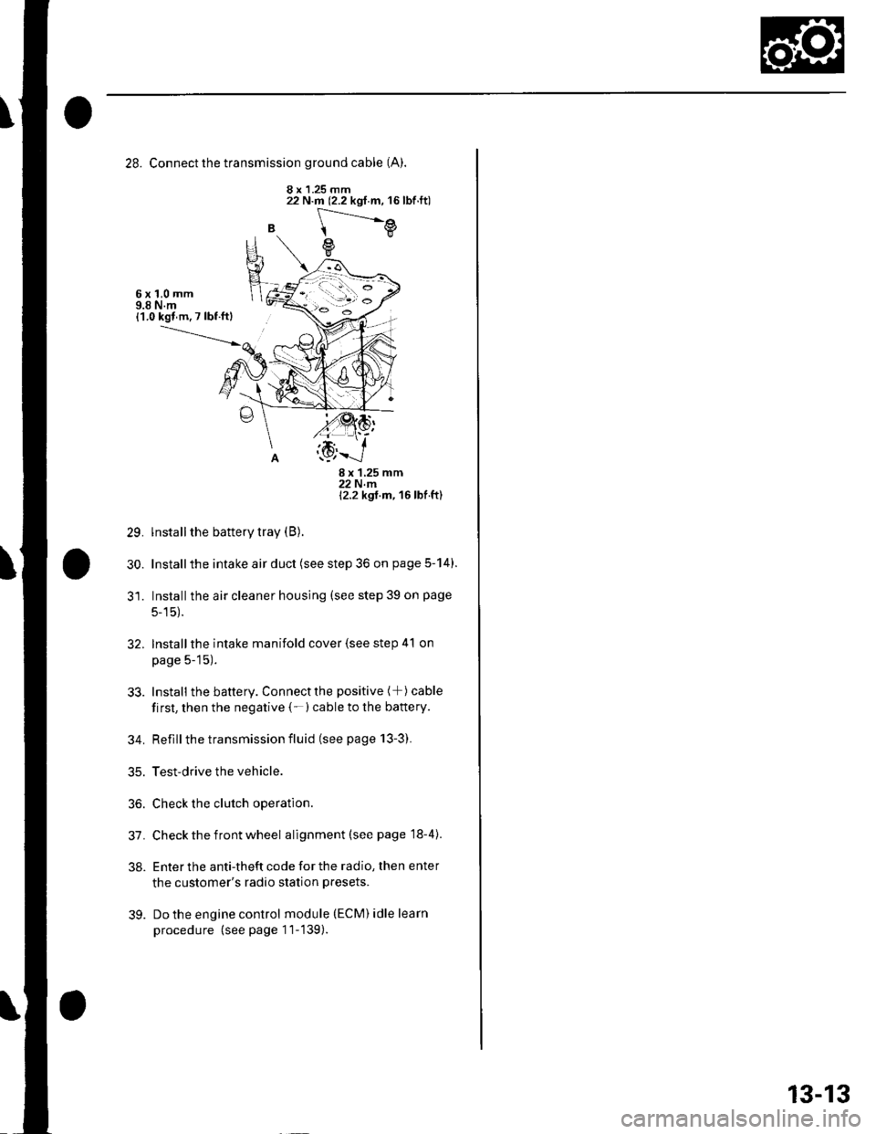
28. Connect the transmission ground cable (A).
8 x 1.25 mm
B
22 N.m (2.2 kgf.m, 16lbf.ft)
[---.-.---e
e
6x1,0mm9.8 N.m{1.0 kgl m. 7 lbf ftl
29.
30.
8x125mm22Nm12.2 kgt m, 16 lbf ft)
lnstall the battery tray (B).
Installthe intake air duct (see step 36 on page 5-14).
Installthe air cleaner housing (see step 39 on page
5-15).
Installthe intake manifold cover (see step 41 on
page 5-15).
Install the battery. Connectthe positive (+) cable
first, then the negative (-)cable to the battery.
Reflllthe transmission fluid (see page 13-3).
Test-drive the vehicle.
Check the clutch operation.
Check the front wheel alignment (see page 18-4).
Enter the anti-theft code for the radio, then enter
the customer's radio station presets.
Do the engine control module (ECM) idle learn
procedure (see page 11-139).
32.
33.
34.
35.
36.
31.
38.
39.
13-13
Page 470 of 1139
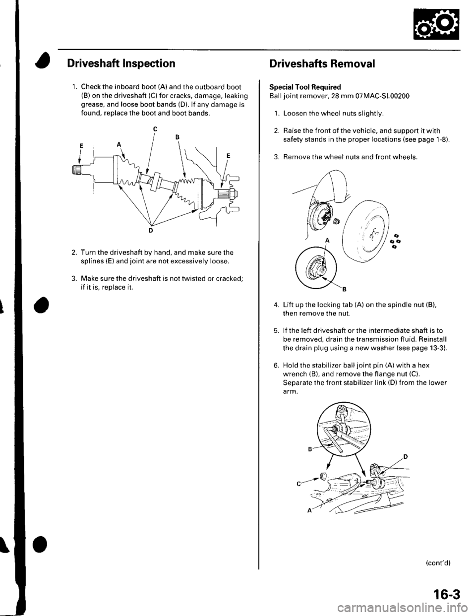
Driveshaft Inspection
1. Check the inboard boot (A) andthe outboard boot(B) on the driveshaft (C) for cracks, damage, leaking
grease, and loose boot bands (D). lf any damage is
found, reDlace the boot and boot bands.
Turn the driveshaft by hand, and make sure the
splines (E) and joint are not excessively loose.
Make sure the driveshaft is not twisted or cracked;
if it is, replace it.
Driveshafts Removal
Special Tool Required
Balljoint remover, 28 mm 07MAC-S100200
1. Loosen the wheel nuts slightly
2. Raise the front of the vehicle, and support it with
safety stands in the proper locations (see page 1-8).
3. Remove the wheel nuts and front wheels.
4.Lift up the locking tab (A) on the spindle nut (B),
then remove the nut.
lf the !eft driveshaft or the intermediate shaft is to
be removed, drain the transmission fluid. Reinstall
the drain plug using a new washer (see page 13-3).
Hold the stabilizer balljoint pin (A) with a hex
wrench {B), and remove the flange nut (C).
Separate the front stabilizer link (D) from the lower
a rm.
(cont'd)
16-3
Page 471 of 1139
Driveline/Axle
Driveshafts Removal (cont'd)
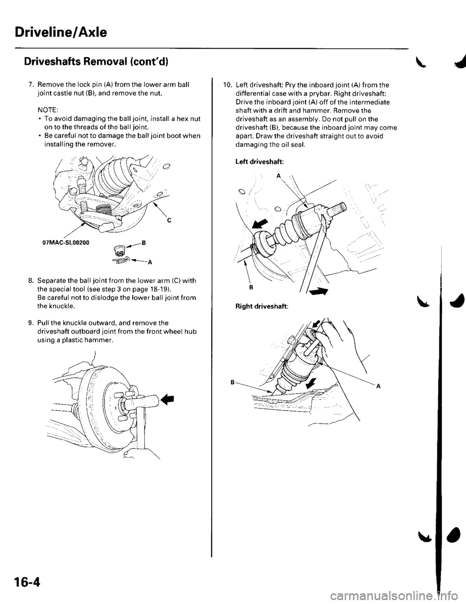
7. Remove the lock pin {A)from the lower arm balljoint castle nut (B), and remove the nut.
NOTE:. To avoid damaging the balljoint, install a hex nut
on to the threads of the ball joint,
. Be careful not to damage the balljoint boot when
installing the remover.
07MAC-S100200
w^'e
Separate the ball joint from the lower arm (C) with
the special tool (see step 3 on page 18-19).
Be careful not to dislodge the lower ball joint from
the knuckle.
Pull the knuckle outward, and remove the
driveshaft outboard joint from the front wheel hub
using a plastic hammer.
9.
.."8
16-4
\
10. Left driveshaft: Pry the inboard joint (A)from the
differential case with a prybar. Right driveshaft:
Drive the inboard joint (A) off of the intermediate
shaft with a drift and hammer. Remove the
driveshaft as an assembly. Do not pull on the
driveshaft (B), because the inboard joint may come
apart. Draw the driveshaft straight out to avoid
damaging the oil seal.
Left driveshaft:
a
t
Right driveshaft:
Page 485 of 1139
Driveline/Axle
Driveshafts Installation (cont'd)
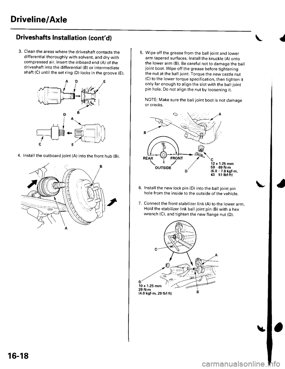
Clean the areas where the driveshaft contacts thedifferential thoroughly with solvent, and dry withcompressed air. Insenthe inboard end {A) ofthedriveshaft into the differential (B) or intermediateshaft {C) until the set ring (D) locks in the groove (E).
4. Install the outboard joint (A) into the front hub (B).
16-18
5. Wipe offthe grease from the ball ioint and lowerarm tapered surfaces. Installthe knuckle (A) ontothe lower arm {B). Be careful not to damage the balljoint boot. Wipe off the grease before tighteningthe nut at the ball joint. Torque the new castle nut(C) to the lower torque specification, then tighten itonly far enough to align the slot with the ball joint
pin hole. Do not align the nut by loosening it.
NOTE: Make sure the ball joint boot is not damageor cracks.
"-'t-
12 x 1.25 mm59 69 N.m(6.0 -7.0 kgf m,43 51 tbt.ftl
Installthe new lock pin {D) into the balljoint pin
hole from the inside to the outside of the vehicle.
Connect the front stabilizer link {A) to the lower arm.Hold the stabilizer link balljoint pin (B) with a hexwrench {C), and tighten the newflange nut {D).
7.
'10 x 1.25 mm39 N.m{4.0 kgf.m,29 lbf.ft)
{
Page 486 of 1139
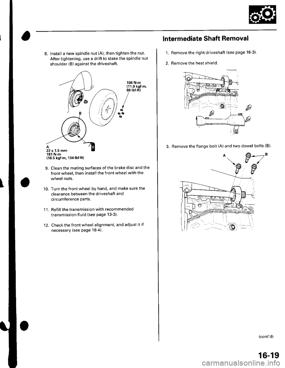
8. Install a new spindle nut {A), then tighten the nut.
After tightening, use a drift to stake the spindle nut
shoulder {B) against the driveshaft.
{18.5 kgf.m, 134lbt.ft)
9. Clean the mating surfaces ofthe brake disc and the
front wheel, then install the front wheel with the
wheel nuts.
10. Turn the front wheel by hand, and make sure the
clearance between the driveshaft and
circumference parts.
1 l. Refill the transmission with recommended
transmission fluid (see page 13-3).
12. Check the front wheel alignment, and adjust it if
necessary (see page 18-4).
108 N.m(11.0 kgf.m,80 tbt.ft)
/oooe
22x 1.5 mm181 N.m
1.
2.
lntermediate Shaft Removal
Remove the right driveshaft (see page 16-3).
Remove the heat shield.
3. Remove the flange bolt {A) andtwodowel bolts(B).
€.---2"EJ/
€w
(cont'd)
16-19
Page 496 of 1139
Steering
Steering Wheel Rotational Play
Check
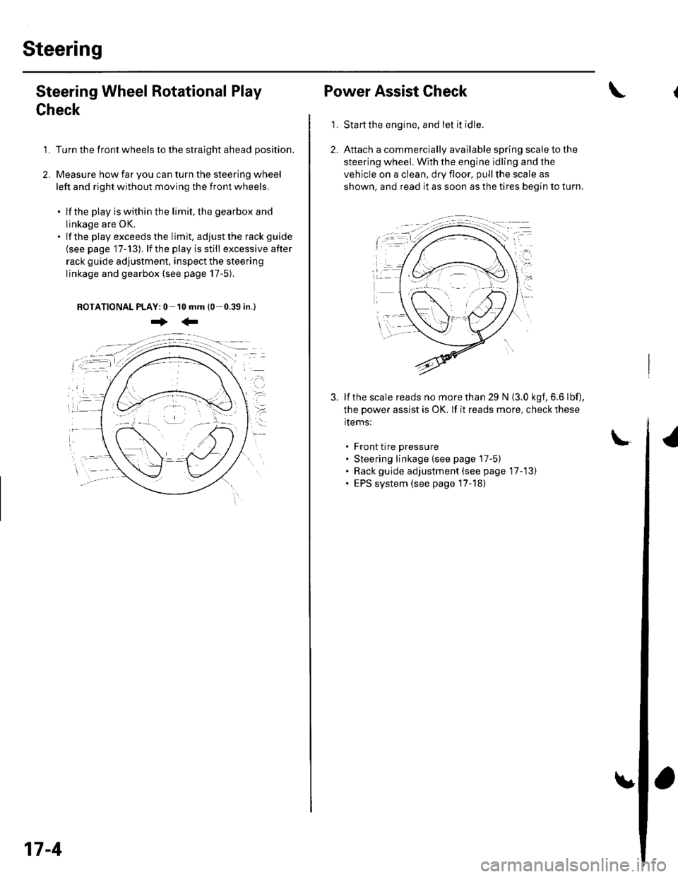
1. Turn the front wheels to the straight ahead position.
2. Measure how far you can turn the steering wheel
left and right without moving the front wheels.
. lf the play is within the limit, the gearbox and
linkage are OK.. lf the playexceedsthe limit, adjustthe rack guide
{see page '17-13). lf the play is still excessive after
rack guide adjustment, inspect the steering
linkage and gearbox {see page 17-5).
BOTATIONAL PLAY: 0 10 mm (0-0.39 in.l
+:
17-4
Power Assist Check
Start the engine, and let it idle.
Attach a commercially available spring scale to the
steering wheel. With the engine idling and the
vehicle on a clean, dry floor, pull the scale as
shown, and read it as soon as the tires begin to turn.
\
1.
3. lf the scale reads no morethan 29 N (3.0 kgf,6.6 lbf),
the power assist is OK. lf it reads more, check these
items:
. Front tire pressure. Steering linkage (see page 17-5). Rack gulde adjustment (see page 17-13). EPS system (see page 17-18)
Page 498 of 1139
Steering
Steering Wheel Removal
SRS components are located in this area. Review the
SRS component locations (see page 23-13), and
precautions and procedures (see page 23-14) in the SRS
section before performing repairs or service.
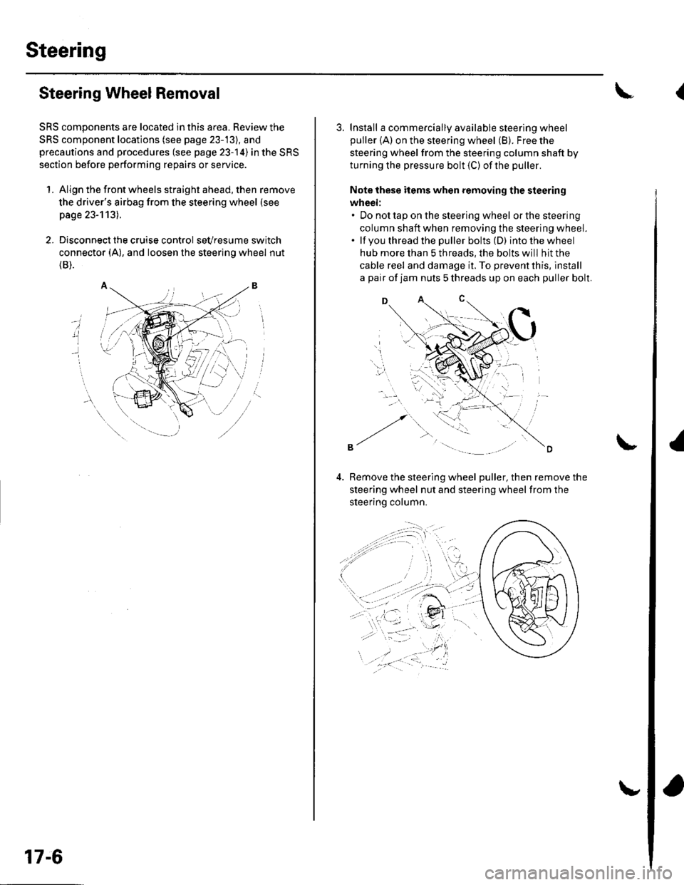
1. Align the front wheels straight ahead, then remove
the driver's airbag from the steering wheel (see
page 23-113).
2. Disconnect the cruise control sevresume switch
connector (A), and loosen the steering wheel nut
{B).
i
17-6
3. Install a commercially available steering wheel
puller {A) on the steering wheel (B). Free the
steering wheel from the steering column shaft by
turning the pressure bolt (C) ofthe puller.
Note these items when removing the steering
wheel:. Do not tap on the steering wheel orthesteering
column shaft when removing the steering wheel.. lf you thread the puller bolts (D) intothewheel
hub more than 5 threads, the bolts will hit the
cable reel and damage it. To prevent this, install
a pair of jam nuts 5 threads up on each puller bolt.
D
Bemove the steering wheel puller, then remove the
steering wheel nut and steering wheel from the
sleerino column.
{
Page 500 of 1139
Steering
Steering Wheel Installation
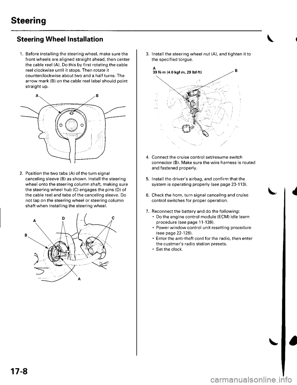
1. Before installing the steering wheel, make sure the
front wheels are aligned straight ahead, then center
the cable reel (A). Do this by first rotating the cable
reel clockwise until it stops. Then rotate it
counterclockwise about two and a half turns. The
arrow mark (B) on the cable reel label should point
straight up.
Position the two tabs (A) of the turn signal
canceling sleeve (B) as shown. Installthe steering
wheel onto the steering column shaft, making sure
the steerlng wheel hub (C) engages the pins (D) of
the cable reel and tabs of the canceling sleeve. Do
not tap on the steering wheel or steering column
shaft when installing the steering wheel.
17-8
3. Install the steering wheel nut (A), and tighten it to
the specified torgue.
A_B39 N.m (4.0 kgf m.29lbt ftl
Connect the cruise control set/resume switch
connector (B). fvlake sure the wire harness is routed
and fastened properly.
Install the driver's airbag, and confirm that the
system is operating properly {see page 23-113).
Check the horn, turn signal canceling and cruise
control switches for proper operation.
Reconnect the battery and do the following:. Do the engine control module (ECM) idle learn
procedure (see page 1l-139),. Power window control unit resetting procedure
\see page 22-1281.. Enter the anti-theft cord for the radio, then enter
the custmer's radio station presets.. Set the clock.
{
7.
lr,',,t
;. _,:!
'' '1i::..'.' l
Page 511 of 1139
EPS Components
General Troubleshooting Information (cont'dl
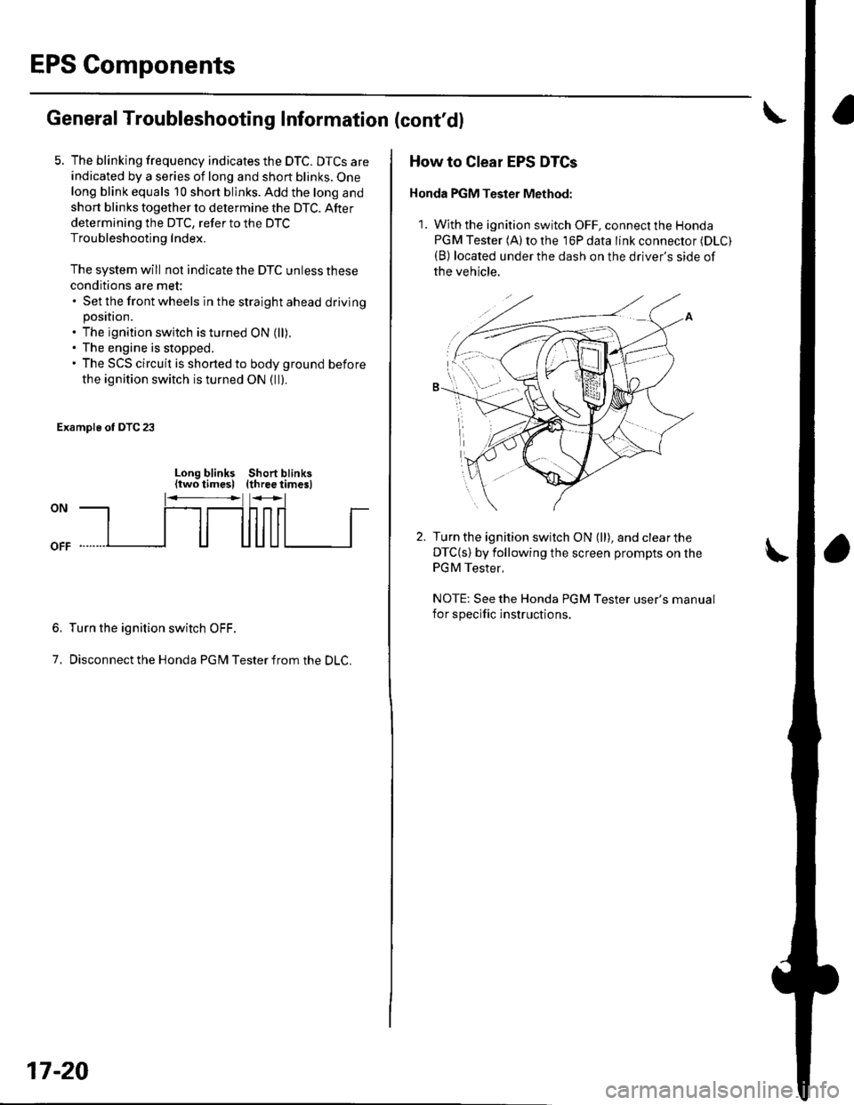
5. The blinking frequency indicates the DTC. DTCS are
indicated by a series of long and short blinks. One
long blink equals 10 short blinks. Add the long and
short blinks together to determine the DTC. After
determining the DTC, refer to the DTC
Troubleshooting Index.
The system will not indicate the DTC unless these
conditions are met:. Set the front wheels in the straight ahead drivingposition.. The ignition switch is turned ON (ll).. The engine is stopped.. The SCS circuit is shorted to body ground before
the ignition switch is turned ON (ll).
Example of DTC 23
Long blinks Short blinks(two times) (three timesl
6.
7.
Turn the ignition switch OFF.
Disconnect the Honda PGM Tester from the DLC.
17-20
How to Clear EPS DTCs
Honda PGM Tesler Method:
1. With the ignition switch OFF, connect the Honda
PGM Tester (A) to the 16P data link connector (DLC)
(B) located under the dash on the driver's side of
the vehicle.
Turn the ignition switch ON (ll), and clear the
DTC{s) by following the screen prompts on the
PGM Tester.
NOTE: See the Honda PGM Tester user's manual
for specific instructions.