evap HONDA CIVIC 2003 7.G User Guide
[x] Cancel search | Manufacturer: HONDA, Model Year: 2003, Model line: CIVIC, Model: HONDA CIVIC 2003 7.GPages: 1139, PDF Size: 28.19 MB
Page 218 of 1139
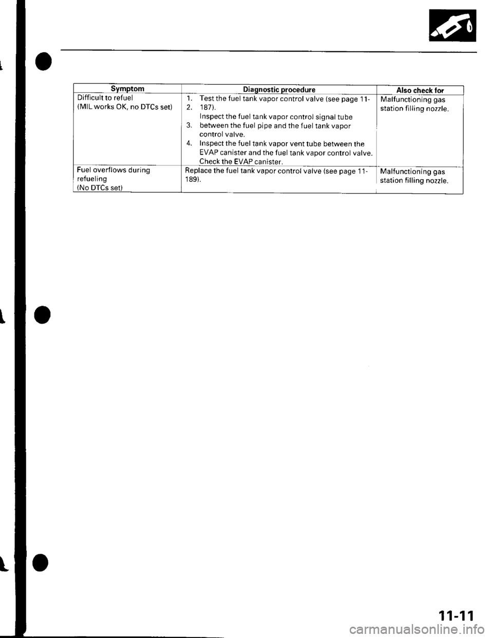
SymptomDiagnostic procedureAlso check torDifficult to refuel(MlL works OK. no DTCS set)
1. Testthefuel tank vapor control valve{seepage 1'l-
2. 1471.
Inspect the fuel tank vapor control signal tube
3. between the fuel pipe and the fuel tank vapor
control valve.
4. Inspect the fuel tank vapor vent tube between the
EVAP canister and the fuel tank vapor control valve.
Check the EVAP canister.
Malfunctioning gas
station filling nozzle.
Fuel overflows during
refueling(No DTCS set)
Replace the fuel tank vapor control valve (see page '1 1
189).
Malfunctioning gas
station filling nozzle.
11-11
Page 224 of 1139
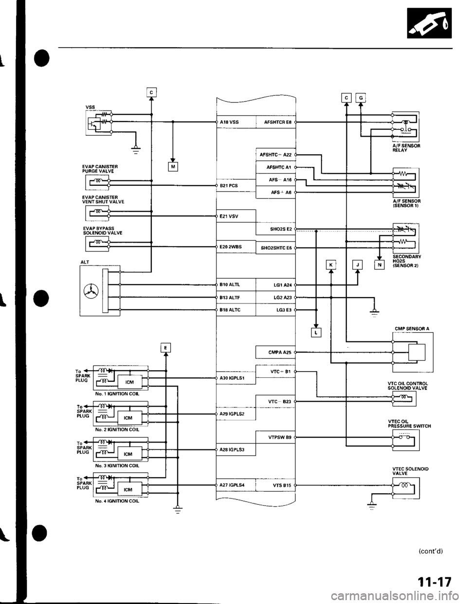
EVAPCANISTE6PURGE VAIVE
EVAPCANISTERVENTSHUTVATVE
sotENotovAtvE
A/FSENSOR
A/FSENSOR(sENSOn 1)
CMP SENSOF A
VIC OIL CONTROLSO!ENOIDVALVE
wEcorlPRESSUSE SWTICH
VTEC SOLENOID
{cont'd)
11-17
No. 1 IGNITION COIL
No.2lGNlllON COIL
No. 3 IGNITION COIL
No. a IGNITION COIL
Page 228 of 1139
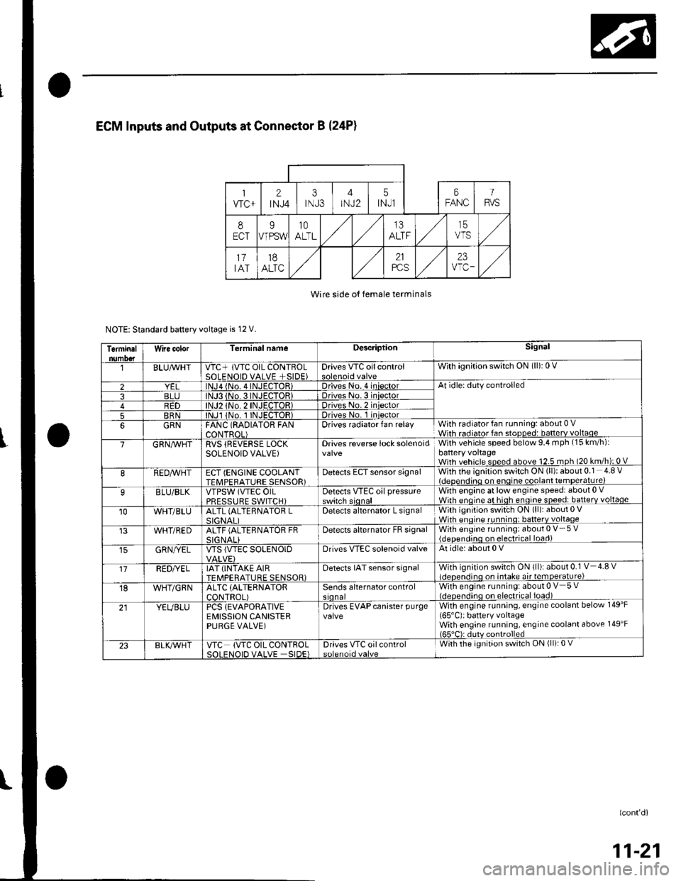
Wire side o{ female terminals
NOTE: Standard baftery voltage is 12 V.
Terminalnumo€tWire color[erminal nameDescriptionSignal
BLUAvHTVTC+ lVTC OIL CONTBOLSOLENOID VALVE +SIDE)Drives VTC oilcontrolWith ignition switch ON (ll): 0 V
2lNJa {No. 4INJECTOR)Driveso. 4 iniectorAt idle: duty controlled
3BLJo.3INJECTORIDriveso.3 iniector4R1)TOR)Driveso.2 iniector
5BRNlNJl 1No. I INJECTOR)Drives No. 1 iniector
6GRNFANC (RAOIATOR FANCONTROL)Drives radiator fan relayWith radiator fan running: about 0 VWith radiator fan stopped: batterv voltaoe
7GRN/vVHTRVS (REVERSE LOCKSOLENOID VALVE)Drives reverse lock solenoidWith vehicle speed below 9.4 mph (15 km/h):battery voltageWith vehicle speed above 12.5 mph (20 km/h): 0 V
8REDAVHTECT (ENGINE COOLANTTFMPFRATURE SENSOR)Detects ECT sensor signalWith the ignition switch ON (ll): about 0.1 4.8 Videoendino on enoine coolant temDerature)
9BLU/BLKVTPSW (VTEC OILPRFSSTIRF SWITCH)Detects VTEc oil pressureswitch sionalWith engine at low engine speed: about 0 .Wirh enoine at hioh enoine soeed: batterv voltaqe
10WHT/BLUALTL (ALTEBNATOR LSIGNAI IDetects alternator L signalWith ignition swit'ch ON (ll): about 0 VWhh enoine runnino: batterv voltaqe
WHT/REDALTF (ALTERNATOR FRSIG NALIDetecls alternator FB signalWith engine running: about 0 V- 5 V{deoendinq on electrical load)
GRN/YELVTS {VTEC SOLENOIDDrives VIEC solenoid valveAt idle: about 0 V
'17REDI/ELIAT (INTAKE AIRTEMPERATURE SENSOR)Detects IAT sensor signalWith ignition switch ON {ll): about 0.1 V 4.8 vl.lcnen.iino on intake air temoerature)
18WHT/GRNALTC (ALTERNATOR
CONTROL)Sends alternator controlWith engine running: about 0 V 5 V(.lcocn.lino on electrical ioad)
21YEUBLUPCS {EVAPORATIVEEMISSION CANISTERPURGE VALVE)
Drives EVAPcanister purgevalveWith engine running, engine coolant below 149'F
165'C): battery voltageWith engine running, engine coolant above 149'F165"C): dutv controlled
23BLK/Vr'HTVTC (VTC OIL CONTROLSOI FNOID VALVE SIDE)Drives VTC oilcontrolWith the ignition switch ON (ll): 0 V
(confd)
11-21
Page 230 of 1139
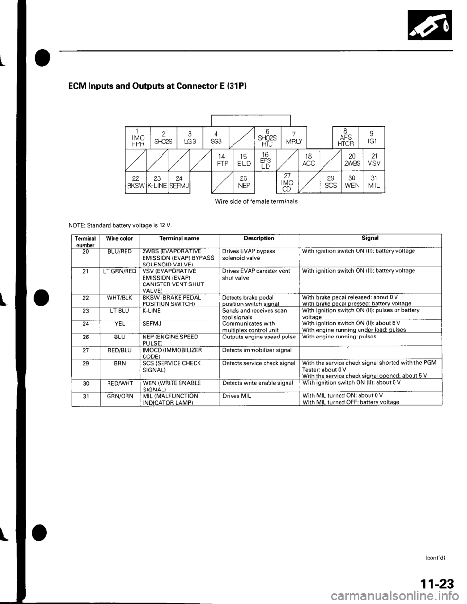
ECM Inputs and Outputs at Connector E (31P)
ltMoFPR
2$.c2s
i6SFIO2SHTC
1
IV RLY
IAFSHTCR
9tGl
14FTP15ELD
16EPSLD
t8202,4/BS21VSV
22BKSW23K LINE24SEFMJ26NEP
21lvoCD
29scs30WEN31MIL
Wire side of female terminals
NOTE: Standard battery voltage is 12 V.
TerminalWire colorTerminalnameDescriptionSignal
20BLU/RED2WBS (EVAPORATIVEEMISSION (EVAP)BYPASSSOLENOID VALVE)
Drives EVAP bypass With ignition switch ON (ll): baftery voltagesolenoid valve
21LT GRN/REDVSV (EVAPORATIVE
EI\4ISSION iEVAP)CANISTEB VENT SHUTVALVE)
Drives EVAP canister ventshut valveWith ignilion switch ON (ll): battery voltage
22WHT/BLKBKSW lBRAKE PEDALPOSITION SWITCH)Detects brake pedaloosition switch sionalWith brake pedal released: about 0 VWith hrake nedal nresse.l: batterv voltaoe23LT BLUK-LIN ESends and receives scanWith ignition switch ON (li)r pulses or battery
YELSEFMJCommunicates withmrltinleY eontrol unitWith ignition switch ON (ll): about 5 VWith enoine runnino under load: DUlses26BLUNEP (ENGINE SPEEDPULSE)Outputs engine speed pulseWith engine running: pulses
21RED/BLU \40CD fl\4MOBTLTZERCODE)Detects imrnobilizer signal
29BRNSCS (SERVICE CHECKSIGNAL)Oetects service check signalWith the service check signal shorted with the PGMTester: about 0 VWiih rhe service check sional ooened: about 5 V
30RED,A/VHTWEN (WRITE ENABLESIGNALiDetects write enable signal With ignition switch ON (ll): about 0 V
GRN/ORNMIL (MALFUNCTION
INDICATOR LAMP)Drives N4lLWith MIL turned ON: about 0 VWith MIL turned OFF: batterv voltaqe
(cont'd)
11-23
Page 231 of 1139
Fuel and Emissions Systems
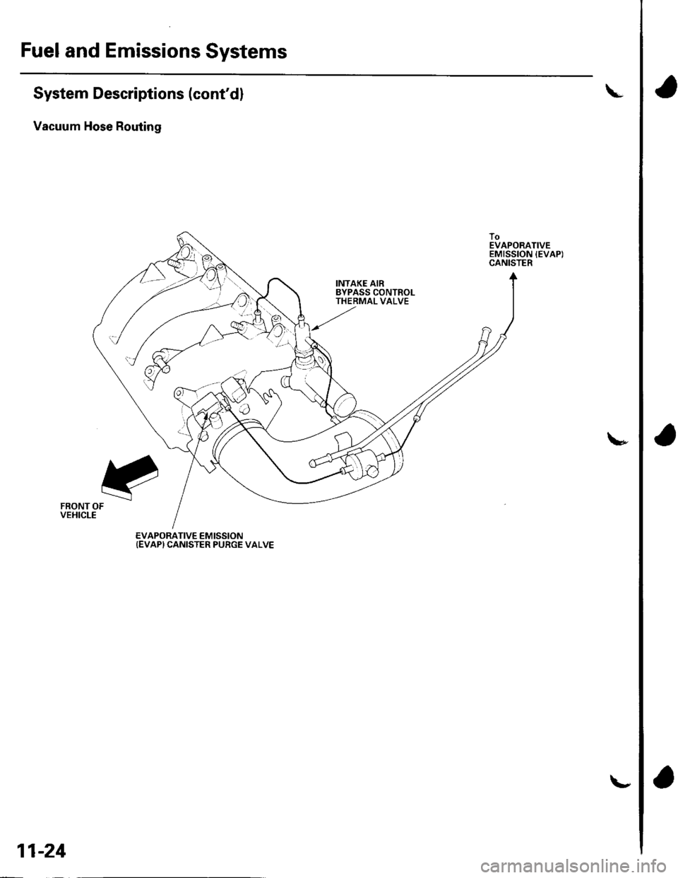
System Descriptions (cont'dl
Vacuum Hose Routing
!
INTAKE AIRBYPASS CONTROLTHERMAL VALVE
\*
FRONT OFVEHICLE
EVAPORATIVE EMISSION{EVAP} CANISTER PURGE VALVE
11-24
\,
Page 232 of 1139
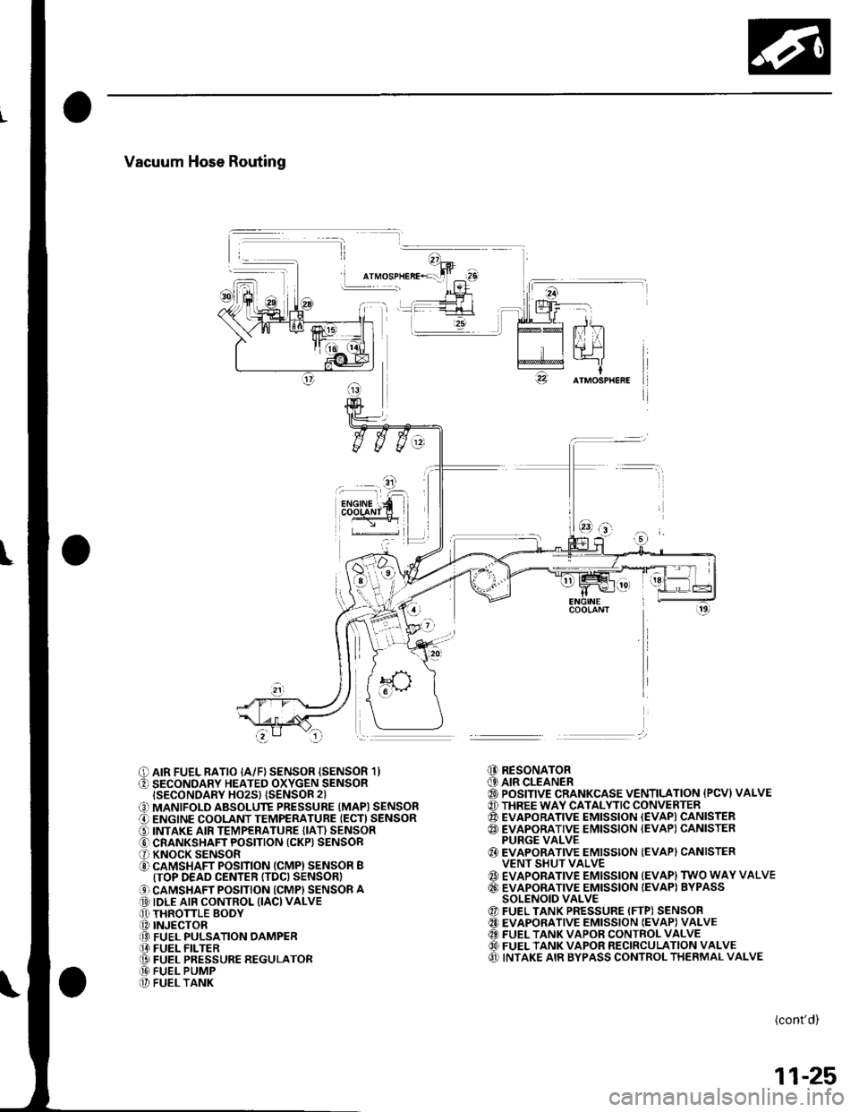
Vacuum Hose Routing
I
O AIR FUEL RATIO IA/F) SENSOR {SENSOR 1}O SECONDARY HEATED OXYGEN SENSORISECONDARY HO2S} {SENSOR 2}
O MANIFOLD ABSOLUTE PRESSURE (MAPI SENSORO ENGINE COOLANT TEMPERATURE {ECT) SENSORO INTAKE AIR TEMPERATURE (IAT) SENSORO CRANKSHAFT POSITION (CKP) SENSORO KNOCK SENSORO CAMSHAFT POSITION (CMPI SENSOR BITOP DEAD CENTER ITDC) SENSOR)
O CAMSHAFT POSITION ICMPI SENSOR A@ IDLE AIR CONTROL (IACI VALVEO THRONLE BODY.O INJECTOR@ FUEL PULSATION OAMPER[I FUEL FILTER@ FUEL PRESSURE REGULATOR@ FUEL PUMP@ FUEL TANK
@ RESONATOR(9 AIR CLEANER@ POSITIVE CRANKCASE VENTILATION {PCVI VALVE@ THREE WAY CATALYTIC CONVERTER@ EVAPORATIVE EMISSION {EVAPI CANISTER@ EVAPORATIVE EMISSION {EVAP) CANISTERPURGE VALVE{} EVAPORATIVE EMISSION (EVAPI CANISTERVENT SHUT VALVE{' EVAPORATIVE EMISSION {EVAP) TWO WAY VALVE@ EVAPORATIVE EMISSION IEVAPI BYPASSSOLENOID VALVE@ FUEL TANK PRESSURE (FTP) SENSOR@ EVAPORATIVE EMISSION IEVAP} VALVE@ FUEL TANK VAPOR CONTROL VALVE60) FUEL TANK VAPOR RECIRCULATION VALVEO INTAKE AIR BYPASS CONTROL THERMAL VALVE
(cont'd)
11-25
Page 242 of 1139
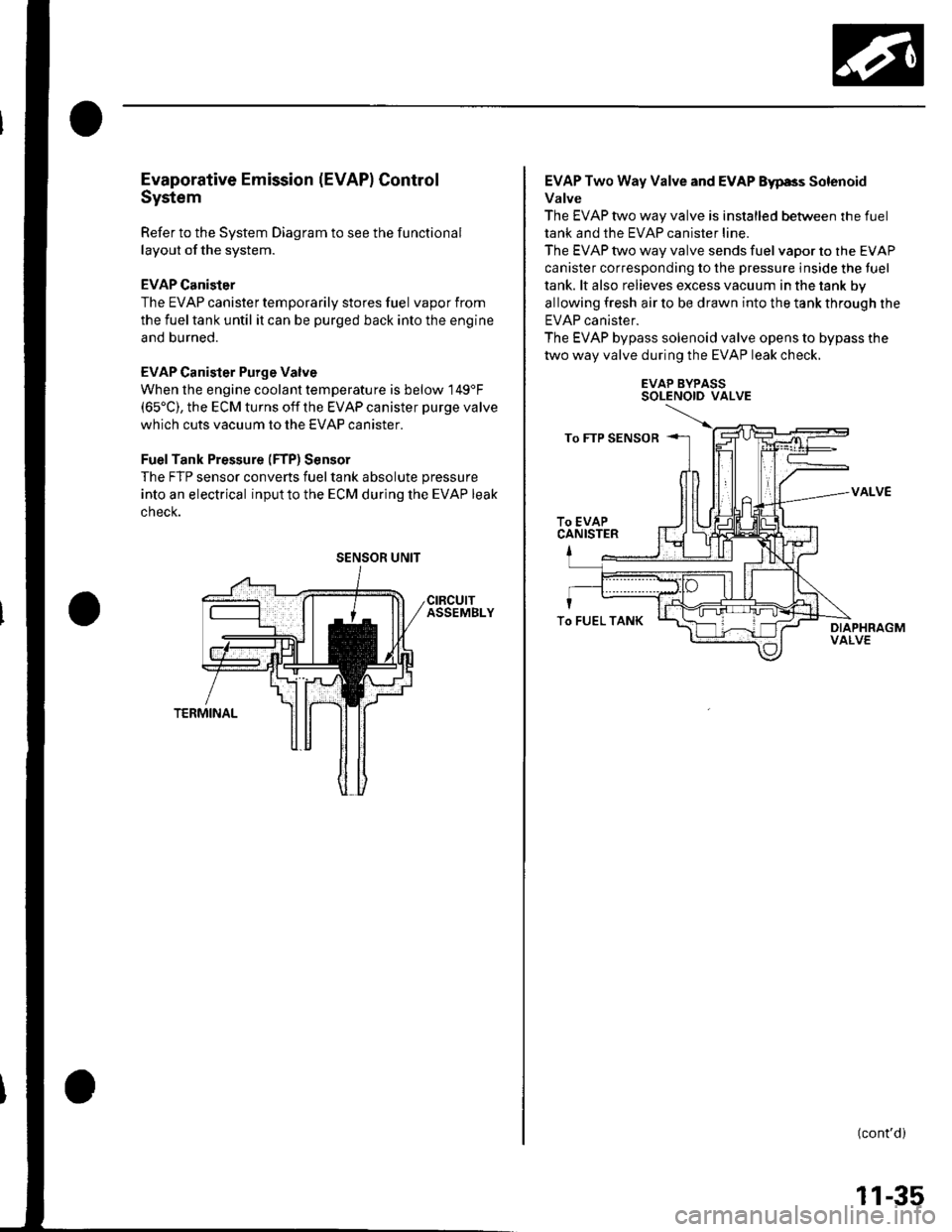
Evaporative Emission (EVAPI Control
System
Refer to the System Diagram to see the functional
layout of the system.
EVAP Canister
The EVAP canister temporarily stores fuel vapor from
the fuel tank until it can be purged back into the engine
and burned.
EVAP Canister Purge Valve
When the engine coolant temperatu re is below 149'F(65'C), the ECM turns off the EVAP canister purge valve
which cuts vacuum to the EVAP canister.
FuelTank Pressure (FTP) Sensor
The FTP sensor converts fueltank absolute pressure
into an electrical inputto the ECM during the EVAP leak
cnecK.
SENSOR UNIT
EVAP Two Way Valve and EVAP Eyp8s Solenoid
Valve
The EVAP two way valve is installed between the fuel
tank and the EVAP canister line.
The EVAP two way valve sends fuel vapor to the EVAP
canister corresponding to the pressure inside the tuel
tank. lt also relieves excess vacuum in the tank by
allowing fresh air to be drawn into the tank through the
EVAP canister.
The EVAP bypass solenoid valve opens to bypass the
two way valve during the EVAP leak check.
EVAP BYPASSSOLENOID VALVE
VALVE
(cont'd)
To FUEL TANK
11-35
Page 244 of 1139
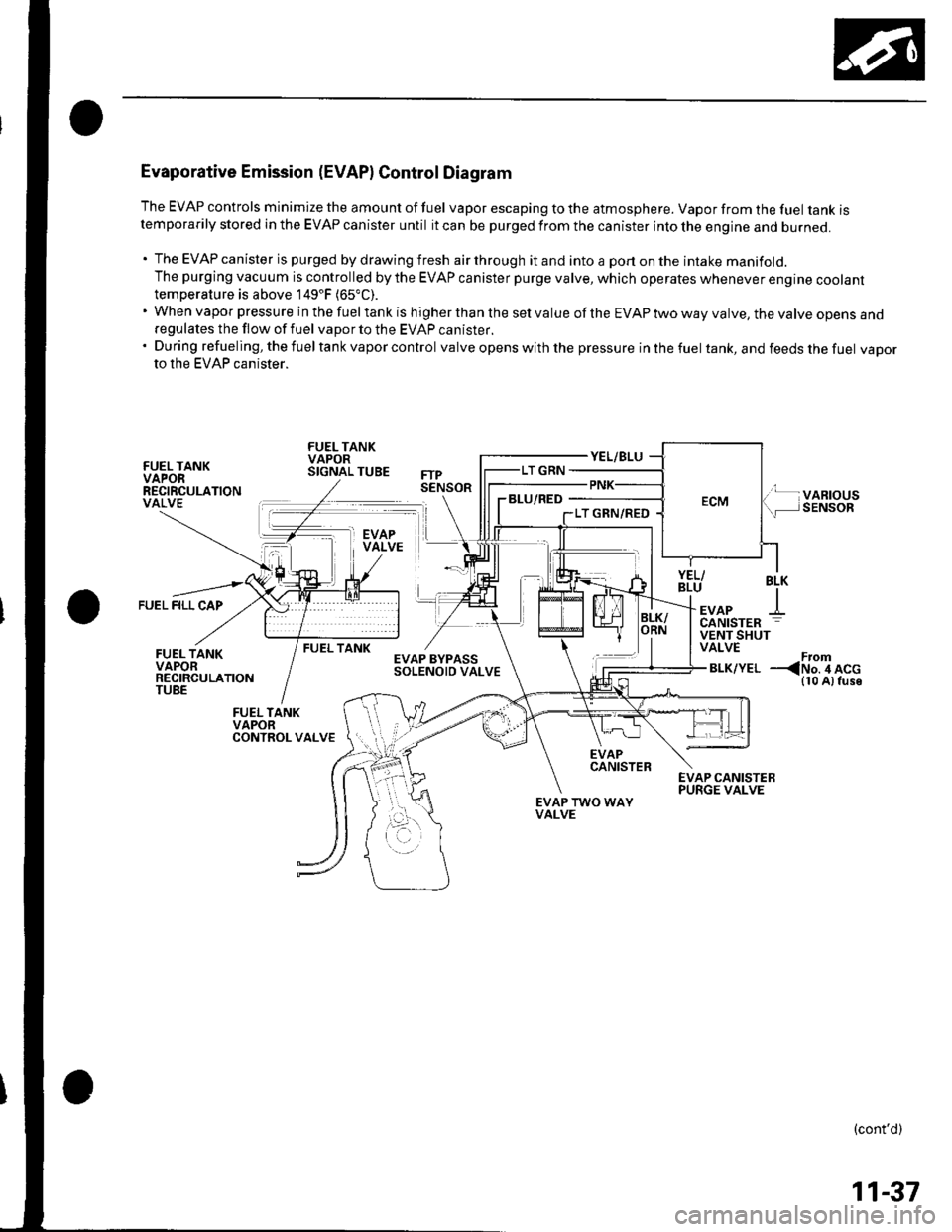
Evaporative Emission (EVAPI Control Diagram
The EVAP controls minimize the amount of fuel vapor escaping to the atmosphere. Vapor from the fuel tanK rstemporarily stored in the EVAP canister until it can be purged from the canister into the engine and burneo.
. The EVAP canister is purged by drawing fresh air through it and into a port on the intake manifold.The purging vacuum is controlled by the EVAP canister purge valve, which operates whenever engine cootanttemperature is above 149'F (65"C).
'WhenvaporpressureinthefueltankishigherthanthesetvalueoftheEVAPtwowayvalve,thevalveopensano
regulates the flow of fuel vapor to the EVAP canister.'Duringrefueling,thefueltankvaporcontrol valve opens with the pressure in the fuel tank, and feeds the fuel vaDorto the EVAP canister.
FUEL TANKVAPORRECIRCULATIONVALVE
FUEL TANKVAPORSIGNAL TUBE
BLU/RED
FUEL FILL CAP
BLK
+EVAPCANISTER
FUEL TANKVENT SHUTVALVE
BLK/YELFrom--
EVAPCANISTER
EVAP TWO WAYVALVE
(cont'd)
11-37
Page 248 of 1139
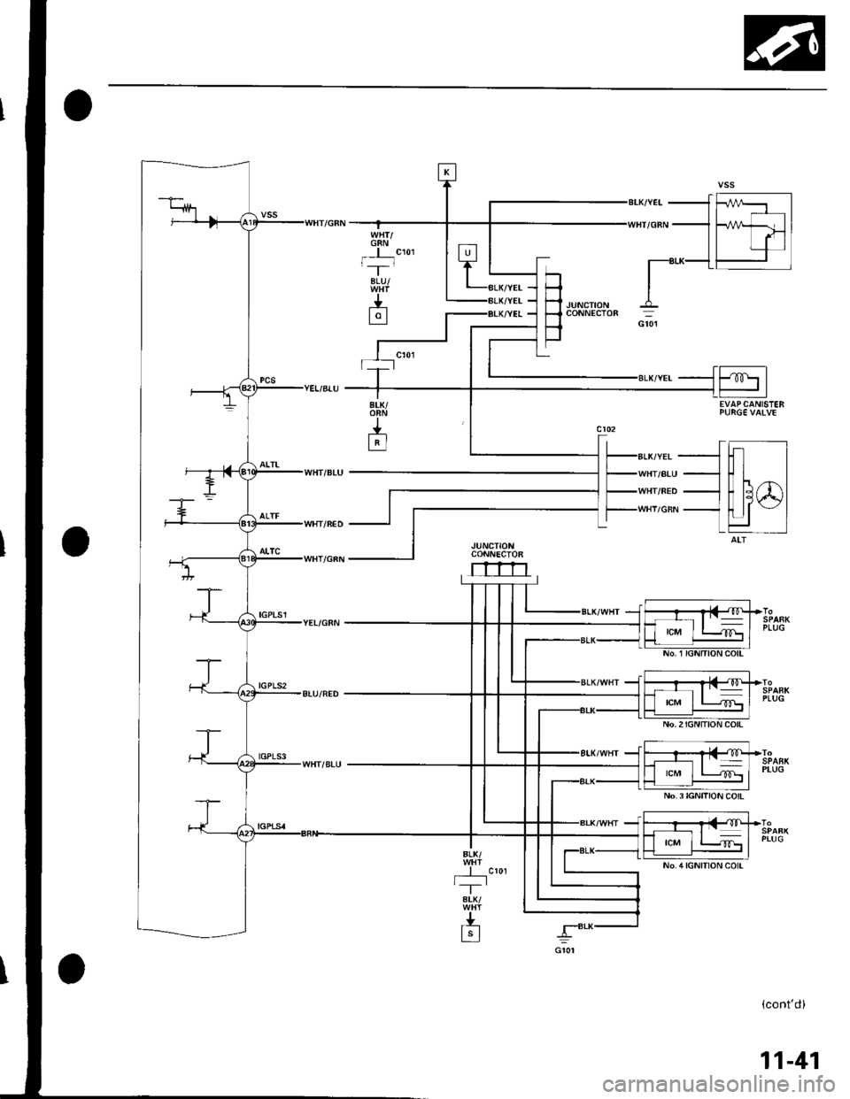
G8Nt,'--r-
BLU/
J.-L9l
H-l .lurcrroru
F
coNNEcroR
_1ffi1
| | -'- |----1 Fahdl
I lrl||T-'8r-K-L- l
EVAPCANISTEB
ALK/YEL
WHT/ALU
WHT/NED
WHI/GRN
JUNCTIONCONNECTOR
rrrn
tcM
No.2IGNITION COlt
No.3IGNITION COIL
PLUG
PLUG
(cont'd)
11-41
Page 250 of 1139
![HONDA CIVIC 2003 7.G User Guide SECONDAFYH02S(s€NsoR 2l
m
tlilTPS€NSOR
--{=l
-{r I
CANISTER VEAITSHUTVALVE
t-_]
--lti lEVAP EYPASSsolENorD
To€PSCONTROLUNIT
CPU
GAUGE ASSEMBTY
(contd)
11-43 HONDA CIVIC 2003 7.G User Guide SECONDAFYH02S(s€NsoR 2l
m
tlilTPS€NSOR
--{=l
-{r I
CANISTER VEAITSHUTVALVE
t-_]
--lti lEVAP EYPASSsolENorD
To€PSCONTROLUNIT
CPU
GAUGE ASSEMBTY
(contd)
11-43](/img/13/5744/w960_5744-249.png)
SECONDAFYH02S(s€NsoR 2l
m
tlilTPS€NSOR
'--{=l
-{r I
CANISTER VEAITSHUTVALVE
t-_]
--lti lEVAP EYPASSsolENorD
To€PSCONTROLUNIT
CPU
GAUGE ASSEMBTY
(cont'd)
11-43