evap HONDA CIVIC 2003 7.G Repair Manual
[x] Cancel search | Manufacturer: HONDA, Model Year: 2003, Model line: CIVIC, Model: HONDA CIVIC 2003 7.GPages: 1139, PDF Size: 28.19 MB
Page 815 of 1139
Heating and Air Conditioning
Heater Unit/Core Replacement (cont'd)
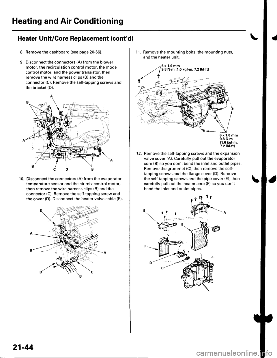
8. Remove the dashboard {see page 20-66).
9. Disconnectthe connectors (A) from the blower
motor, the recirculation control motor, the mode
control motor, and the power transistor, then
remove the wire harness clips (B) and the
connector (C). Remove the self-tapping screws and
the bracket (D).
Disconnect the connectors (A) from the evaporator
temperature sensor and the air mix control motor,
then remove the wire harness clips (B) and the
connector (C). Remove the self-tapping screw and
the cover (D). Disconnect the heater valve cable (E).
10,
7t,
21-44
11. Remove the mounting bolts, the mounting nuts,
and the heater unit.
Remove the self-tapping screws and the expansion
valve cover (A). Carefully pull out the evaporator
core (B) so you don't bend the inlet and outlet pipes.
Remove the grommet (C), then remove the self-
tapping screws and the flange cover (D). Bemove
the self-tapping screws and the pipe cover (E), then
carefully pull out the heater core (F) so you don't
bend the inlet and outlet oioes.
@
5x 1.0 mm9.8 N.m11.0 kgl m,7.2 tbf.ftl
12.
Page 816 of 1139
13. Installthe heater core and the evaporator core in
the reverse order of removal.
14. Installthe heater unit in the reverse order of
removal, and note these items:
. Do not interchange the inlet and outlet heater
hoses, and installthe hose clamps securely.. Refillthe cooling system with engine coolant (see
page 10-6).. Adjust the heater valve cable (see page 2'l-461.. Make sure that there is no coolant leakage.. Make sure that there is no air leakage.. Refer to evaporator core replacement {see step 6
on page 21-42).. Do the engine control module (ECl\4) idle learn
procedure (see page 11-139).. Enter the anti-theft code for the radio, then enter
the customer's radio station Dresets.
21-45
Page 828 of 1139
A/C System Tests
Pressure Test
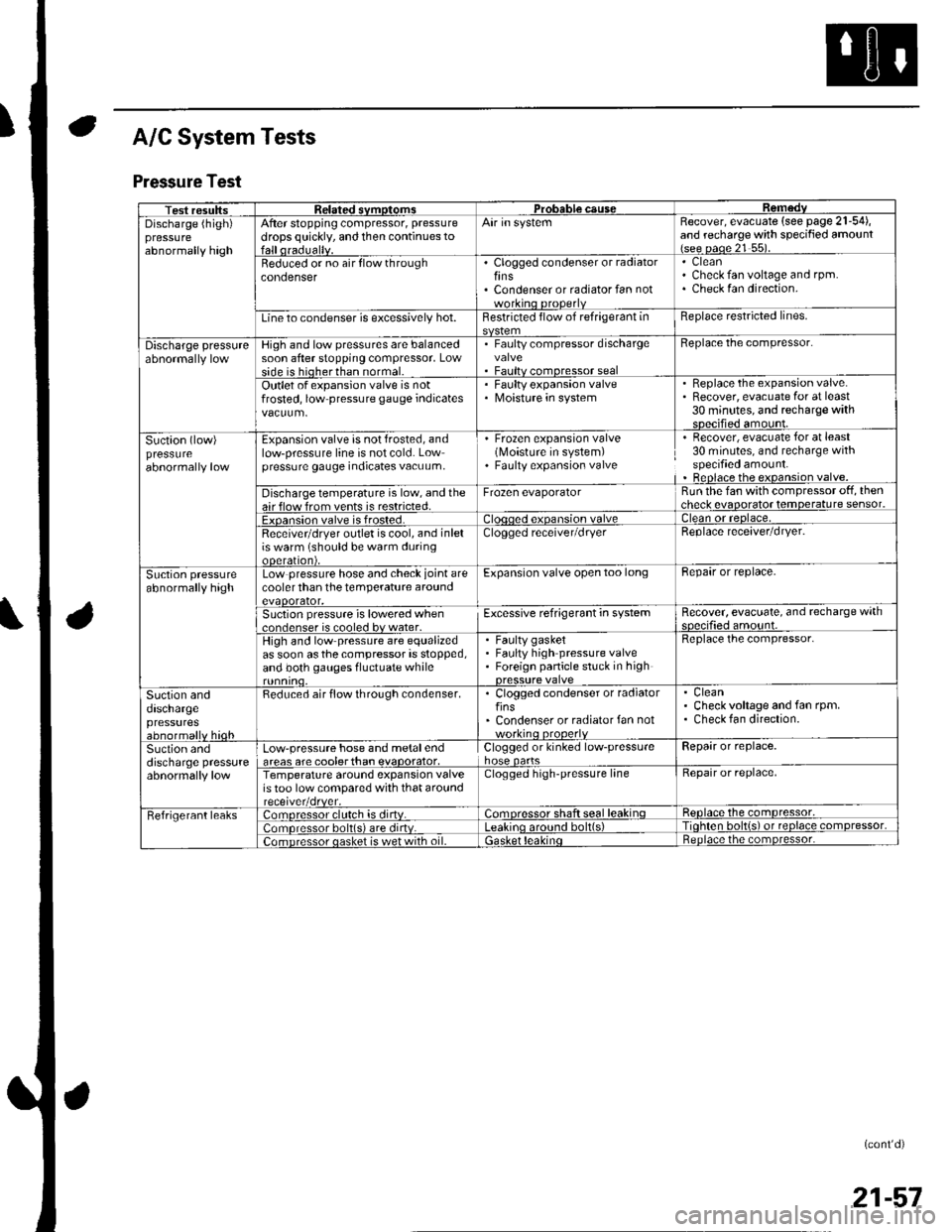
Test resultssvmotom3DGaUSeDischarge (high)pressureabnormally high
After stopping compressor, pressure
drops quickly, and then continues toAir in systemRecover, evacuate (see page 21-54),and recharge with specified amount{see oaoe 21 55).
Beduced or no air flow throughcondenserClogged condenser or radiatorfinsCondenser or radiator fan not
CleanCheck fan voltage and rpm.Check fan direction.
Line to condenser is excessively hot.Restricted flow of refrigerant inReplace restricted lines.
Discharge pressureHigh and low pressures are balancedsoon after stopping compressor, Lowside is hioherthan normal.
. Faulty compressor dischargevalve. Faultv comoressor seal
Beplace the compressor.
Outlet of expansion valve is notfrosted, low pressure gauge indicatesFaulty expansion valveMoisture in system
. Replace the expansion valve.. Recover, evacuate for at least30 minutes, and recharge withsDecified amount.
Suction (low)pressureabnormally low
Expansion valve is not frosted, andlow-pressure line is not cold. Lowpressure gauge indicates vacuum,
' Frozen expansion valve(Moisture in system). Faulty expansion valve
Recover, evacuate for at least30 minutes, and recharge withspecified amount.Beplace the expansion valve.
Discharge temperature is low, and theair flow from vents is restricted.Frozen evaporatorRun the fan with compressor off, thencheck evaooratot temoerature sensor.
Exoansion valve is frosted.ean or reolace,
Receivetdryer outlet is cool, and inletis warm (should be warm duringooeralton),
Clogged receiver/dryerReplace receaver/dryer.
Suction pressureabnormally highLow pressure hose and check joint arecooler than the temperature aroundevaoorator,
Expansion valve open too longBepair or replace.
Suction pressure is lowered when..nrlenser is cooled bv water.Excessive refrigerant in systemRecover, evacuate, and recharge withqnp.ifie.lamo'rnr
High and low pressure are equalizedas soon asthecompressor is stopped,and both gauges fluctuate while
Faulty gasketFaulty high pressure valveForeign panicle stuck in high
Replace the compressor.
Suction anddaschargepressuresabnormallv hioh
Reduced air flow through condenser.. Clogged condenser or radiatorfins' Condenser or radiator fan notworkino orooerlv
CleanCheck voltage and fan rpm.Check fan direction.
Suction anddischarge pressureabnormally low
Low-pressure hose and metalendareas are coolerthan evaoorator,Clogged or kinked low-pressurehose oartsRepair or replace.
Temperature around expansion valveis too low compared with that aroundClogged high-pressure lineRepair or replace,
Fefrigerant leaks:omoressor clulch is dirtv.:omoressor shaft seal leakinqReolace the comDressor,
lomoressor bolt(s) are dirtv.no around bolt(s)Tiohten bolt{s) ot reolace comDressor,
;omDressor oasket is wet with oil.ietnoace the comoressor.
(cont'd)
21-57
Page 847 of 1139
Connectors and Harnesses
Engine Wire Harness
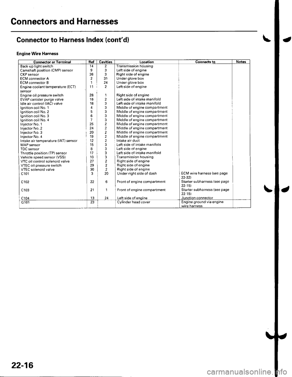
Camshaft position (CMP) sensorLllr sensorEC[,4 connector AECI/l connector BEngine coolant temperature (ECT)
sensorEngine oil pressure switchEVAP canister purge valveldle air control (lAC)valve
lgnition coil No. llgnition coil No. 2lgnition coil No. 3lgnition coil No. 4Iniector No. 1Inlector No.2Iniector No.3Iniector No. 4Intake air temperature {lAT) sensor
TDC sensorThrottle position (TP) sensorVehicle speed sensor (VSSI
VTC oil control solenoid valveVTEC oil pressure switchVTEC solenoid valvec 101
c102
233
242
Transmission housingLeft side of engineRight side ofengineUnder glove boxUnder glove boxLeft side of engine
Bight side oI engineLeft side of intake manifoldLeft side of intake manifoldMiddle of engine compartmentMiddle of engine compartmentMiddle of engine compartmentMiddle of engine compartmentMiddle of engine compartmentMiddle of engine compartmentMiddle of engine compartmentMiddle of engine companment
28
1845672524201912
811102729303
22
12333332222233
322220
Left side of intake manifoldLeft side of engineLeft side of intake manifoldTransmission housingRight side o{ engineRight side of engineRight side of engineUnder right side of dash
Front of engine companment
Front of engine compartment
ECM wire harness {see page22-321Starter subharness (see page22-15)Starter subharness (see page22 151
Connector to Harness Index (cont'dl
22-16
Page 867 of 1139
Gonnectors and Harnesses
a
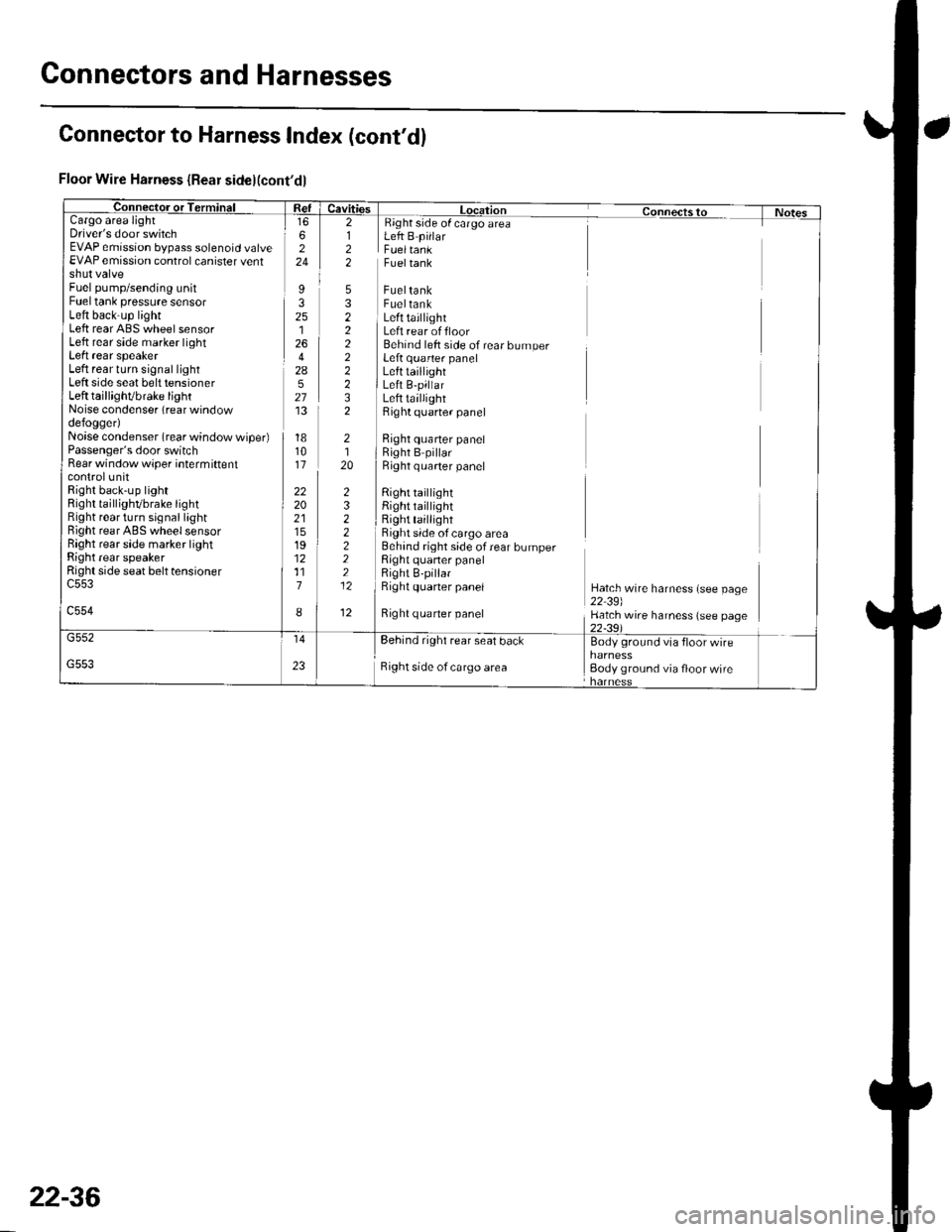
Floor Wire Harness {Rear side}(cont'dl
Cargo areaDriver's door switchEVAP emission bypass solenoid valveEVAP emission control canister ventshut valveFuel pump/sending unitFuel tank pressure sensorLeft back-up lightLeft rear ABS wheel sensorLeft rear side marker lightLeft rear speakerLeft rear turn signal lightLeft side seat belt tensionerLeft taillighVbrake lightNoise condenser (rear windowdefogger)Noise condenser (rear window wiper)Passenger's door switchRear window wiper intermiftentcontrolunitRight back-up lightRight taillighvbrake tightRight rear turn signal lightBight rear ABS wheel sensorRight rear side marker lightRight rear speakerRight side seat belt tensioner
c554
Fueltank
FueltankFueltankLeft taillightLeft rear offloorBehind left side of rear bumperLeft quarter panelLefttaillightLeft B-pillarLeft taillightRight quarter panel
Right quarter panelRight B pillarRight q uarter panel
Right tai ightRight taillightRight taillightRight side of cargo area
side of cargo areaLeft B pillarFueltank
Right quaner panel
6224
I32512642A527'13
181011
222021151912117
I
2122
5322222232
232222212
12
2120
Behind right side of rear bumperRight quaner panelRight B-pillarRight quaner panelHatch wire harness (see page22 39)Hatch wire harness (see page
rear seal bdcl Bodv ground vta
Right side of cargo area Body ground via floor wire
Connector to Harness Index (cont'dl
22-36
Page 874 of 1139
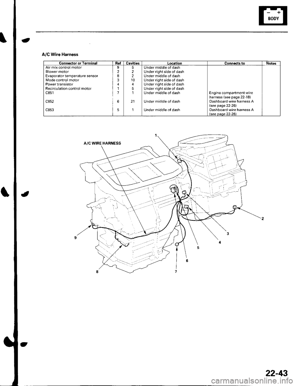
A/C Wire Harness
Connoctor or TerminalRelCavitiesLocationConnec'tstoNotesAir mix control motorBlower motorEvaporator temperature sensorMode control motorPowertransistorRecirculation control motorc851
c852
c853
I283411
6
5
52210
51
21
,]
Under maddle of dashUnder right side of dashUnder middle of dashUnder right side of dashUnder right side of dashUnder right side of dashUnder middle ol dash
Under middle ofdash
Under middle o{ dash
Engine compartment wireharness (see page 22-18)Dashboard wire harness A{see page 22 26iDashboard wire harness Alsee oaoe 22-261
22-43
Page 878 of 1139
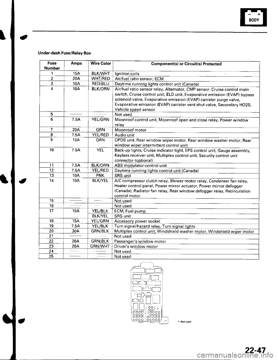
Under-dash Fuse/Relay Box
Fuse
Number
AmpsWire ColorComponent(s) or Circuit(s) Protected
115ABLKA/VHTlgnition coils
2204WHT/REDAirlfuel ratio sensor, ECM
310ARED/BLUDaytime running Iights control unit {Canada)10ABLI(ORNAir/fuel ratio sensor relay, Alternator, CMP sensor, Cruise control main
switch, Cruise control unit. ELD unit, Evaporative emission (EVAP) bypass
solenoid valve, Evaporative emission (EVAP)canister purge valve,
Evaporative emission (EVAP) canister vent shut valve, Secondary H02S,
Vehicle speed sensor
5Not used
67.5AYEUGRNMoonroof control unit, Moonroof open and close relay, Power window
relaV
7204GRNMoonroof motor
I7.5AYEUREDAudio unit
910AGRNOPDS unit, Rear window wiper motor, Rear window washer motor, Rear
window wiper intermittent control unit
107.54YELBack-up lights, Cruise indicator light, EPS control unit, Gauge assembly,
Keyless receiver unit, Multiplex control unit, Security control unit
connector (optional)
117.5ABLIVORNABS modulator-control unit
127.5AYEUREDDaytime runnino liohts control unit (Canada)
1310APNKSRS unit't410ABLK/YE LA,,/C compressor clutch relay, Blower motor relay, Condenser fan relay,
Heater control panel, Power mirror actuator, Power mirror defogger(Canada), Radiator fan relay, Rear window defogger relay, Recirculation
control motor1ENot used
loNot used
1715AYE L/B LKECM, Fuel pump
B LK/YE L>H> Unrr
1815AYEUGRNAccessory power socket
197.5AYEUBLKTurn siqnal/hazard relav, Turn siqnal liohts
2030AGRN/BLKMultiplex control unit, Windshield washer motor. Windshield wioer motor21Not used
22204GRN/BLKPassenqer's window motor
2320A.G R N,A/VHTDriver's window motor
24Not used
25Not used
__^:Hr tl_l
f at-t
at I
r^,rl fl
!!;r -
!339,i;s!!sf Fnf : |rnITf
22-47
Page 1135 of 1139
)
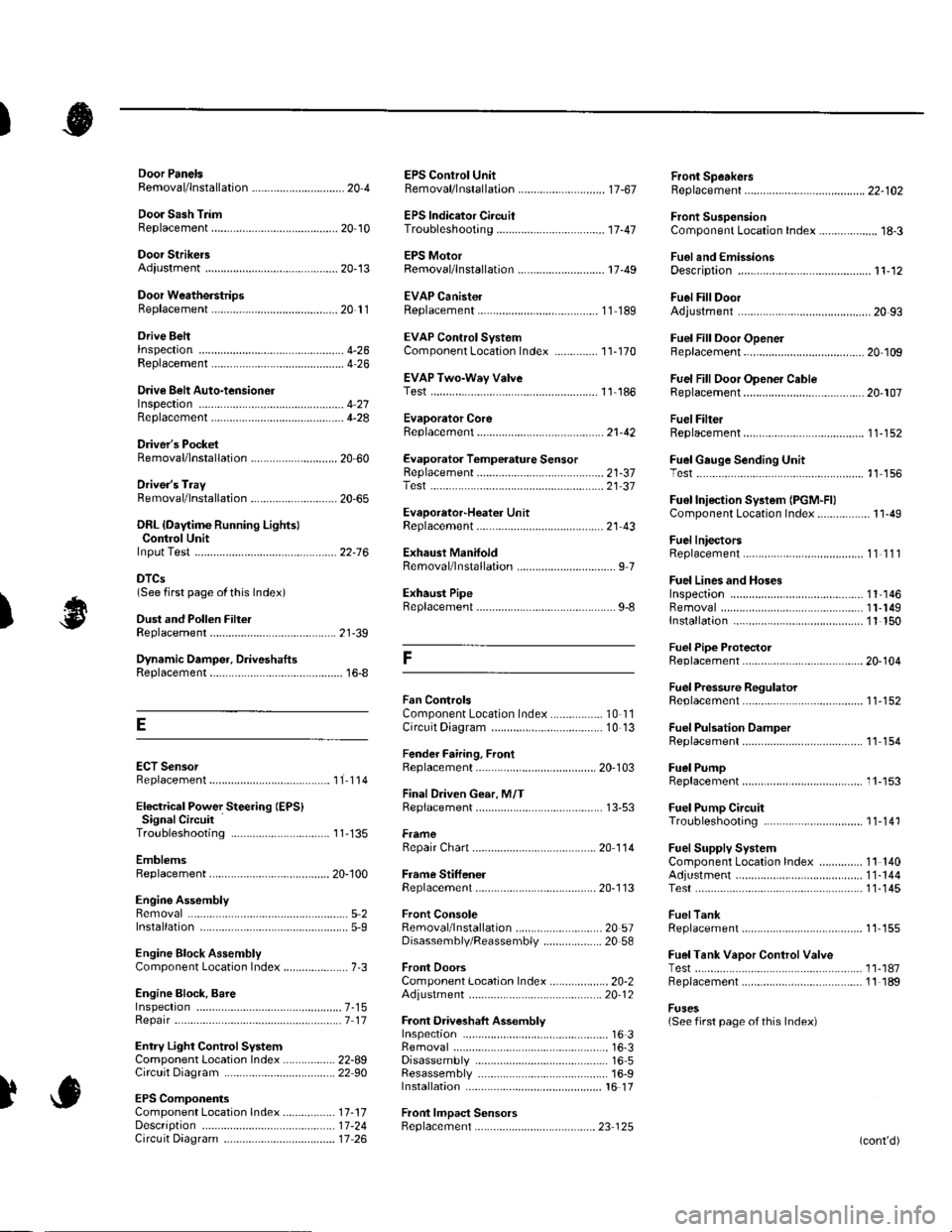
Orive BehInspecaron................ 4-26
Door PanelsRemoval/lnstallation -............................. 20-4
Door Sash TrimRep1acement......................................... 20 10
Door StrikersAdiustment ........................................... 20-13
Door Weatherst psBeplacement...........-............................. 20 1 1
EPS Conirol UnitRemoval/1nsta11ation ..................-......... 17-67
EPS Indicator CircuitTroubleshooting ................................... 17 -47
EPS MotorRemoval/lnstallation .-.......................... 17-49
EVAP CanisterRep1acement......................... ......... 11,189
EVAP Control Syst€mComponentLocation Index ..............'11-170
EVAP Two-Wey ValveTest ..........-.............-............................ 11 186
Evaporetor CoreRep1acement........................ . ... 21-42
Evaporator Tomperature SensorReplacement......................................... 21 -37Test..................................... ..........2137
EvaporrtoFHeater UnitReplacement........................................ 21 43
Exhaust ManifoldRemoval/1nsta11ation ................................ I 7
Exhaust Pipe8ep|acement............................................. 9-8
Front SpeakersRep|acement....................................... 22-102
Front SuspensionComponentLocation Index................... 18-3
Fueland EmissionsDescription ........................................... 11-12
Fuel Fill DoorAdjustment ..........-................................ 20 93
Fuel Fill Door OpenetBeplacement........................ . ............ 20.109
Fuel Fill Door Opener CableReplacement....................................... 20- lO7
Fuel FilterReplacement....................................... 1 1-152
Fuel Gauge Sending UnitTest ......................-.-..........-.................. 11'156
Fuel Injection Syslem (PGM"FIlComponent Location 1ndex................. 11-49
Fuel IniectorsRep1acemen1....................................... 1 1 1 1 l
Fuel Lines and HosesInspection .......................................... 1 1'146Removal ....................... . .. . .... 11-149Insta|1ation .......................................... 1 1 150
FuelPipe ProtectolReplacement....................................... 20-104
Fuel Pressure RegulatotReplacement....................................... 1 1-152
Fuel Pulsation DamperReplacemenl................................... 11 154
Fuel PumpReplacement,,,,,.,.,.,,,.,,,,,,,,,,,,.,.,.,,,..,.. 11-153
Fuel Pump CircuitTroubleshooting -.......-....................... 1 1-141
FuelSupply SystemComponent Location lndex .............. 11 140Adjustment................................... 11-144Test........-...-................. ... ............- 11-145
FuelTankBeplacemenl.............. . ..... .. 11 155
Fuel Tank Vapor ControlValveTest ......................-....... ... . . 11-187Replacement,,.,,...,.,,,.,.,,,,... .. .. 11 189
Fuses{See first page ofthis Index)
)
Rep|acement................. ..................... 4 26
Drive Belt Auto-tensionellnspection ............................................... 4 21Rep1acement.................................... ..4-28
Driver's PocketRemoval/lnstallation -........................... 20-60
Driver's TrayRemoval/lnstallation .........................-.- 20-65
DRL {Daytime Running LightslControl Unitlnput Test .................... ........ . . . ......22-16
DTCs(See first page olthis Index)
Dust and Pollen FillerReplacement......................................... 21-39
Dynamic Damper, DriveshaftsReplacement........................................... 16-8
ECT SensorReplacement.,.,,,.,.,,,,,,,,,,,,,,................ 1 1-1 14
El€ctrical Power Steering IEPS)Signal CircuitTroubleshooting ........ ... .. 11-135
EmblemsReplacement......................-................ 20-100
Engine AssemblyRemova1 .................................................... 5 2Installation ............._.................................. 5-9
Engine Block AssemblyComponent Location Inder ..................... 7.3
Engine Block, BareInspect|onRepair
Fan ControlsComponent Location Index................. 10'l 1Circuit Diagram .. ..... . .. . .................. 10 13
Fender Fairing, FrontReplacement...-................................... 20-103
Final Driven Gear. M/TReplacement.... . . ................................ 13-53
FrameRepair Chan............ ... ....................... 20 11 4
Frame StiffenelReplacement......-................................ 20- J'13
Front ConsoleRemoval/lnstallation ............................ 20 5lDisassembJy/Reassemb|y ................... 20 58
Front DoorsComponent Location Index................... 20-2Adiustment ........................................... 20.12
Front Driveshaft AssemblyInspeclion .................... ... ....16 3Remova1...................-...... ... .....16-3Disassembly ............................... .....165Resassemb|y ................................-......... 16-9Insta11arion ........................ ...... ............ l6 17
Front lmpact SensorsRep1acement............................ ...23 125
................7-15................1 11
)
Entry Light Control SystemComponent Location Index ...............-. 22-89Circuit Dia9ram .................................... 22 90
EPS ComponentsComponent Location 1ndex..........-...... 17-!7Description ........................ ...... ..17-24Circuit Diagram11 26(cont'd)