evap HONDA CIVIC 2003 7.G Owner's Manual
[x] Cancel search | Manufacturer: HONDA, Model Year: 2003, Model line: CIVIC, Model: HONDA CIVIC 2003 7.GPages: 1139, PDF Size: 28.19 MB
Page 254 of 1139
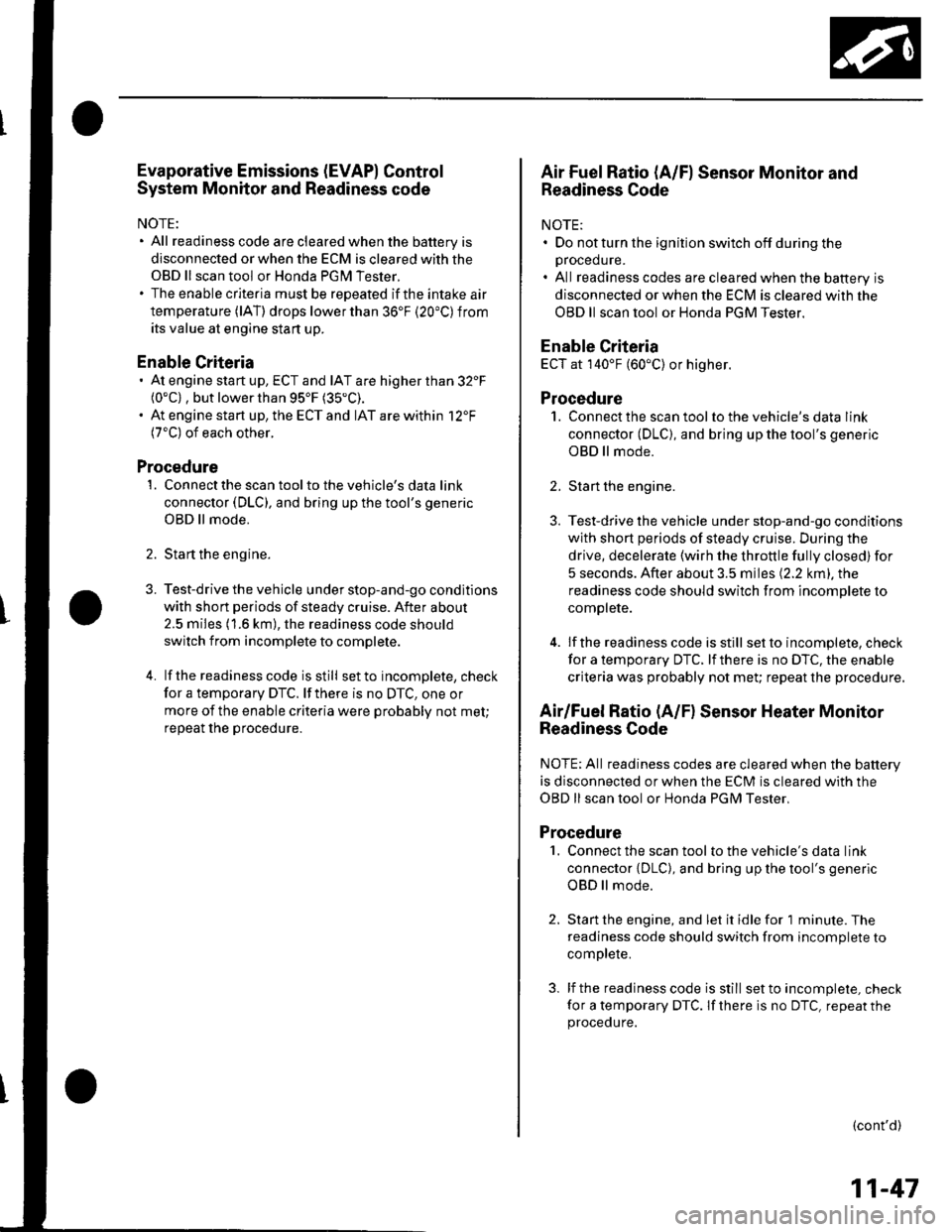
Evaporative Emissions (EVAP) Control
System Monitor and Readiness code
NOTE:
All readiness code are cleared when the batterV is
disconnected or when the ECM is cleared with the
OBD ll scan tool or Honda PGM Tester.
The enable criteria must be repeated if the intake air
temperature (lAT) drops lower than 36'F (20"C) from
its value at engine $an up.
Enable Criteria
At engine start up, ECT and IAT are higher than 32'F(0"C) , but lower than 95'F (35"C).
At engine start up, the ECT and IAT are within 12'F(7'C) of each other.
Procedure
1. Connect the scan tool to the vehicle's data link
connector (DLC), and bring up the tool's generic
OBD ll mode.
2. Start the engine.
3. Test-drive the vehicle under stop-and-go conditions
with short periods of steady cruise. After about
2.5 miles (1.6 km), the readiness code should
switch f rom incomplete to complete.
4. lf the readinesscode isstill setto incomplete, check
for a temporary DTC. lf there is no DTC, one or
more of the enable criteria were probably not met;
repeat the procedure.
Air Fuel Ratio (A/Fl Sensor Monitor and
Readiness Code
NOTE:. Do not turn the ignition switch off during the
orocedure.. All readiness codes are cleared when the baftery is
disconnected or when the ECM is cleared with the
OBD ll scan tool or Honda PGM Tester.
Enable Criteria
ECT at 140'F (60"C) or higher.
Procedure
1. Connect the scan toolto the vehicle's data link
connector (DLC), and bring up the tool's generic
OBD ll mode.
2. Start the engine.
3. Test-drive the vehicle under stop-and-go conditions
with short periods of steady cruise. During the
drive, decelerate (wirh the throttle fully closed) for
5 seconds. After about 3.5 miles (2.2 km). the
readiness code should switch from incomDlete to
complete.
4. lfthereadinesscodeisstill set to incomplete, check
for a temporary DTC. lfthere is no DTC, the enable
criteria was probably not meU repeat the procedure.
Air/Fuel Ratio (A/Fl Sensor Heater Monitor
Readiness Code
NOTE; All readiness codes are cleared when the battery
is disconnected or when the ECM is cleared with the
OBD ll scan tool or Honda PGM Tester,
Procedure'1. Connect the scan tool to the vehicle's data link
connector {DLC), and bring up the tool's generic
OBD ll mode.
2. Start the engine, and let it idle for 1 minute. The
readiness code should switch from incomplete to
comDlete.
3. lf the readiness code is still set to incomplete, check
for a temporary DTC. lf there is no DTC, repeat theproceoure.
(cont'd)
11-47
Page 255 of 1139
Fuel and Emissions Systems
a
a
How to Set Readiness Codes (cont'd)
Misfire Monitor and Readiness Code
. This readiness code is always set to available
because misfiring is continuously monitored.. l\4onitoring pauses, and the misfire counter resets, if
the vehicle is driven over a rough road.. Monitoring also pauses, and the misfire counter
holds at its current value. if the throttle position
changes more than a predetermined value, or if
driving conditions fall outside the range of any
related enable criteria,
Fuel System Monitor and Readiness Code
. This readiness code is always setto available
because the fuel system is continuously monitored
during closed loop operation.. Monitoring pauses when the catalytic converter,
EVAP control system, and Ay'F sensor monitors are
active.. Monitoring also pauses when any related enable
criteria are not being met. Monitoring resumes when
lhe enable criteria is again being met.
Comprehensive Component Monitor and
Readiness Code
This readiness code is always set to available because
the comprehensive component monitor is continuously
running whenever the engine is cranking or running.
11-48
\-
L
Page 277 of 1139
PGM-FI System
DTC Troubleshooting (cont'dl
DTC P0171: Fuel System Too Lean
DTC P0172: Fuel System Too Rich
NOTE: lf some of the DTCS listed below are stored at
the same time as DfC PO17'l and/ot PO172,
troubleshoot those DTCS first, then recheck for P0171
andlot P0112.
P0107, P0108. P1 128. P1 129: Manifold absolute
pressure (MAP) sensor
P1 162. P1 166, P 1 167: 4,,/F sensor (Sensor 1 ) heater
P0137, P0138: Secondary HO2S (Sensor 2)
P014'l: Secondary HO2S (Sensor 2) heater
P1259: VTEC system
1. Check the fuel pressure (see page 11-'145).
ls luel pressure OK?
YES Go to step 2.
NO Check these items:
. lf the pressure is too high, replace the fuel
pressure regulator (see page 11-152).1. lf the pressure istoo low.checkthefuel pump,
the fuel feed pipe, the fuel filter, and replace the
fuel pressure regulator (see page 11-152).I
2. Start the engine. Hold the engine at 3,000 rpm with
no load (in neutral) until the radiator fan comes on.
11-70
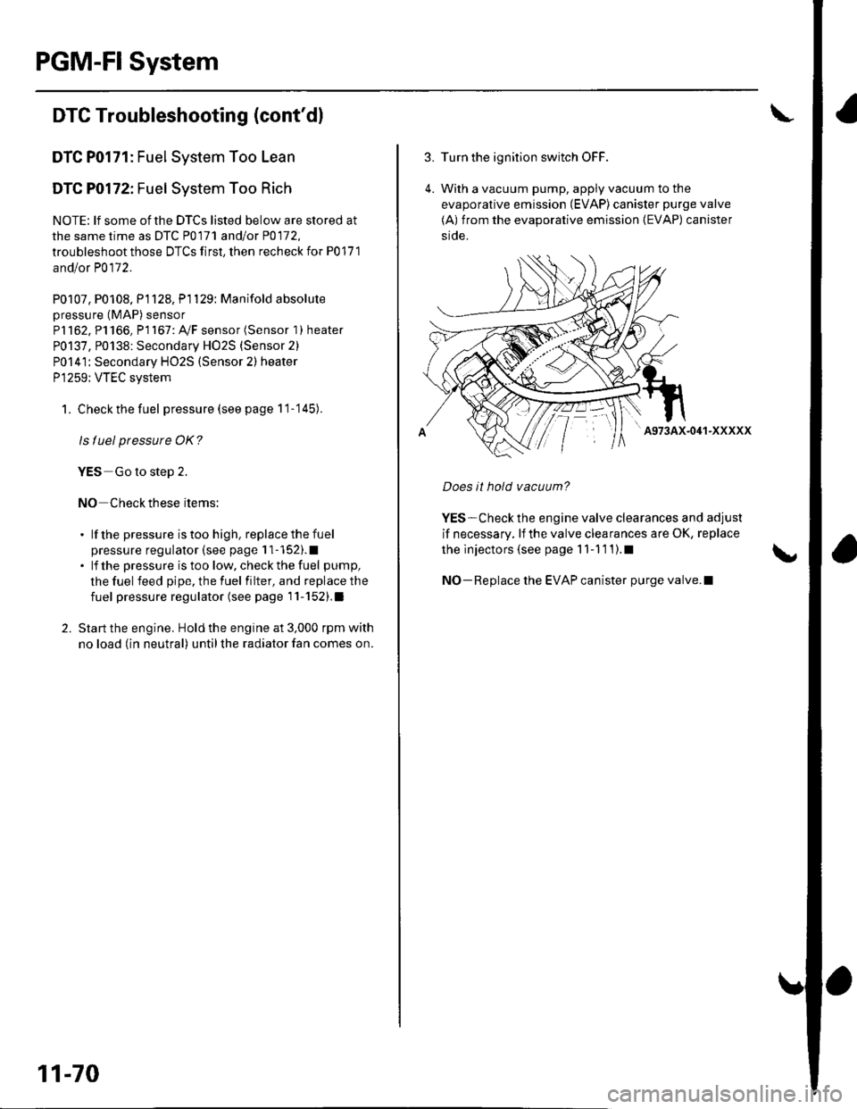
3. Turn the ignition switch OFF.
4. With a vacuum pump, apply vacuum to the
evaporative emission (EVAP) canister purge valve
(A) from the evaporative emission (EVAP) canister
side.
' A973AX-041-XXXXX
Does it hold vacuum?
YES-Check the engine valve clearances and adjust
if necessary, lf the valve clearances are OK, replace
the injectors (see page 1 1-1 1 1).1
NO-Replace the EVAP canister purge valve.l
Page 345 of 1139
ldle Control System
ldle Speed lnspection
NOTE:' Leave the idle air control (lAC) valve connecled.. Before checking the idle speed, check these items:- The malfunction indicator lamp (MlL) has not been
reported on.- lgnition timing- Spark plugs- Air cleaner- PCV system. Pullthe parking brake lever up. Start the engine, and
make sure the headlights are off.
1. Disconnect the evaporative emission (EVAP)
canister purge valve 2P connector.
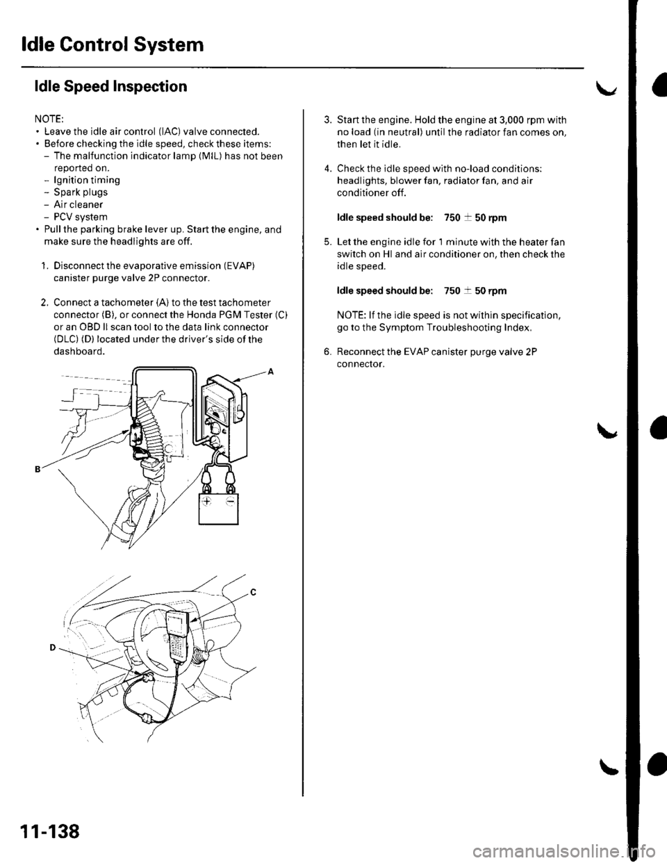
2. Connect a tachometer (A)to the test tachometer
connector (B), or connect the Honda PGM Tester (C)
or an OBD ll scan tool to the data link connector(DLC) (D) located under the driver's side of the
dashboard.
11-138
4.
3.
5.
6.
Start the engine. Hold the engine at 3,000 rpm with
no load (in neutral) until the radiator fan comes on,
then let it idle.
Check the idle speed with no-load conditions;
headlights, blower fan, radiator fan, and air
conditioner off.
ldle speed should be: 750 t 50 rpm
Let the engine idle for 1 minute with the heater fan
switch on Hl and air conditioner on, then check the
idle speed.
ldle speed should be: 750 t 50 rpm
NOTE: lf the idle speed is not wilhin specification,
go to the Symptom Troubleshooting Index,
Reconnect the EVAP canister purge valve 2P
connector.
Page 372 of 1139
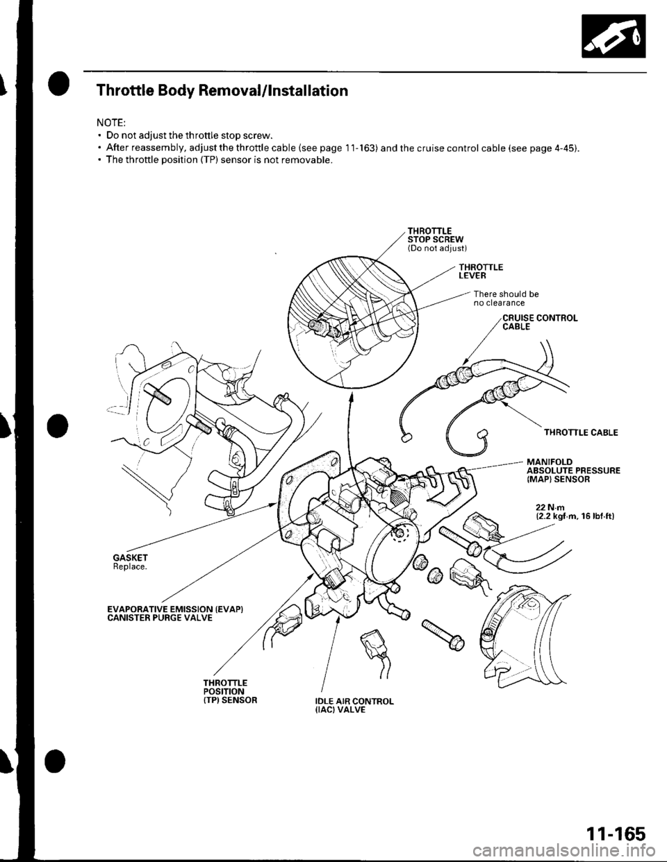
Throttle Body Removal/lnstallation
NOTE:' Do not adjust the throttle stop screw.. Afterreassembly,adjustthethrottlecable{seepagell-163) and the cruise control cable (see page 4-45).. The throttle position (TP) sensor is not removable.
THROTTLELEVER
There should beno clearance
THROTTLE CABLE
MANIFOLDABSOLUTE PRESSURE{MAP} SENSOR
22Nm(2.2 kgt.m, 16 lbf.ft)
EVAPORATIVE EMISSION {EVAPICANISTER PURGE VALVE
IDLE AIR CONTROL{IACI VALVE
11-165
Page 373 of 1139
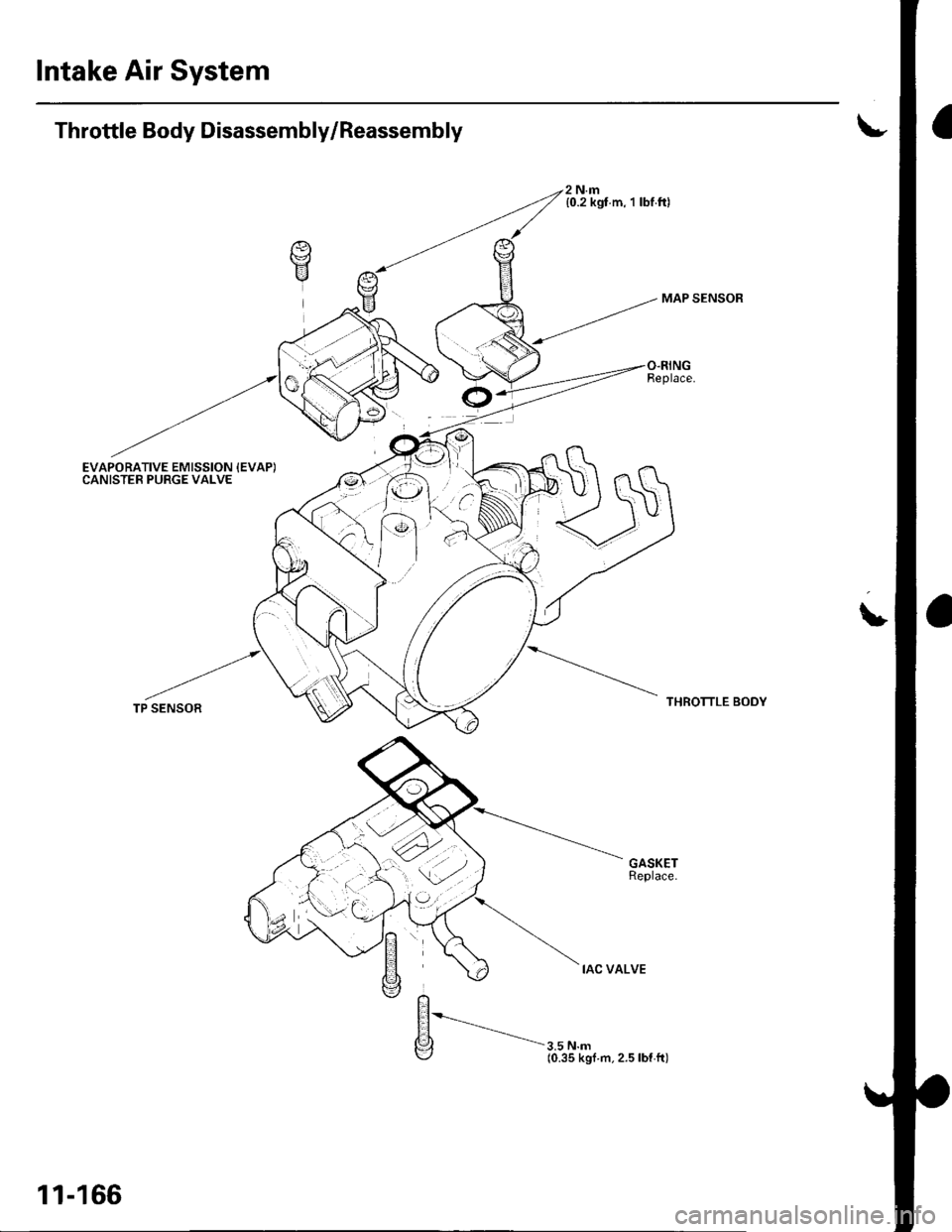
Intake Air System
Throttle Body Disassembly/Reassembly
EVAPORATIVE EMISSION {EVAP)CANISTER PURGE VALVE
A
V
2 N.m{0.2 kgt m, 1 lbf.ft)
3.5 N.m(0.35 kgf m.2.5lbf ft)
MAP SENSOR
THROTTLE BODY
L
TP SENSOR
11-166
Page 375 of 1139
PCV System
DTC Troubleshooting
DTC P1505: PCV Air Leakage
1. Reset the ECM (see page 11-4).
2. Start the engine. Hold the engine at 3,000 rpm with
no load (in neutral) until the radiator fan comes on
3. Let the engine idle tor al least 40 seconds with the
throttle fully closed.
4. Check for a DTC P1505 with the scan tool
ls DTC P1505 indicated?
YES-Check these parts for vacuum leaks l
. PCV valve. PCV hose. EVAP canister purge valve
. Throttle body. Brake booster hose
NO - Intermittent failure, system is OK at this
time.l
11-168
Page 377 of 1139
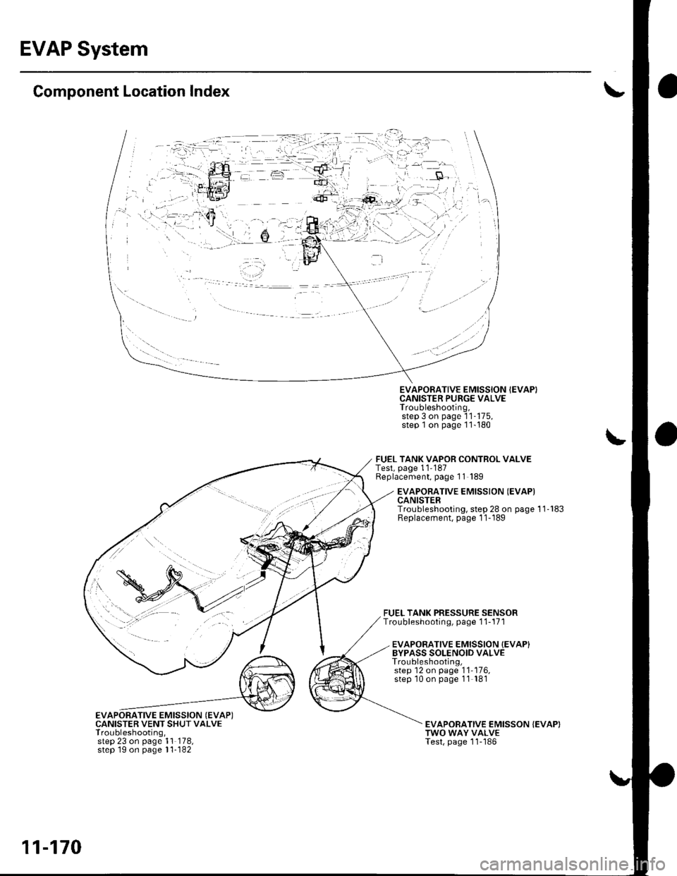
EVAP System
Component Location Index
EVAPORATIVE EMISSION {EVAP)CANISTER VENT SHUT VALVETroubleshooting,step 23 on page 1'l 178,step 1g on page l1- 182
EVAPORATIVE EMISSION IEVAPICANISTER PURGE VALVETroubleshooting,step 3 on page 'l1-175,
step 1on page 11-180
FUEL TANK VAPOR CONTROL VALVETest, page 11'187Replacement, page 11 189
FUEL TANK PRESSURE SENSORTroubleshooting, page 1 1-171
EVAPORATIVE EMISSION {EVAPICANISTERTroubleshooting, step 28 on page 11'183Replacement, page 1 1-189
EVAPORATIVE EMISSION {EVAP}BYPASS SOLENOID VALVETroubleshooting,step 12 on page '11'176,
step '10 on page 11 181
EVAPOBATIVE EMISSON {EVAP)TWO WAY VALVETest, page 'l1-'186
11-170
Page 378 of 1139
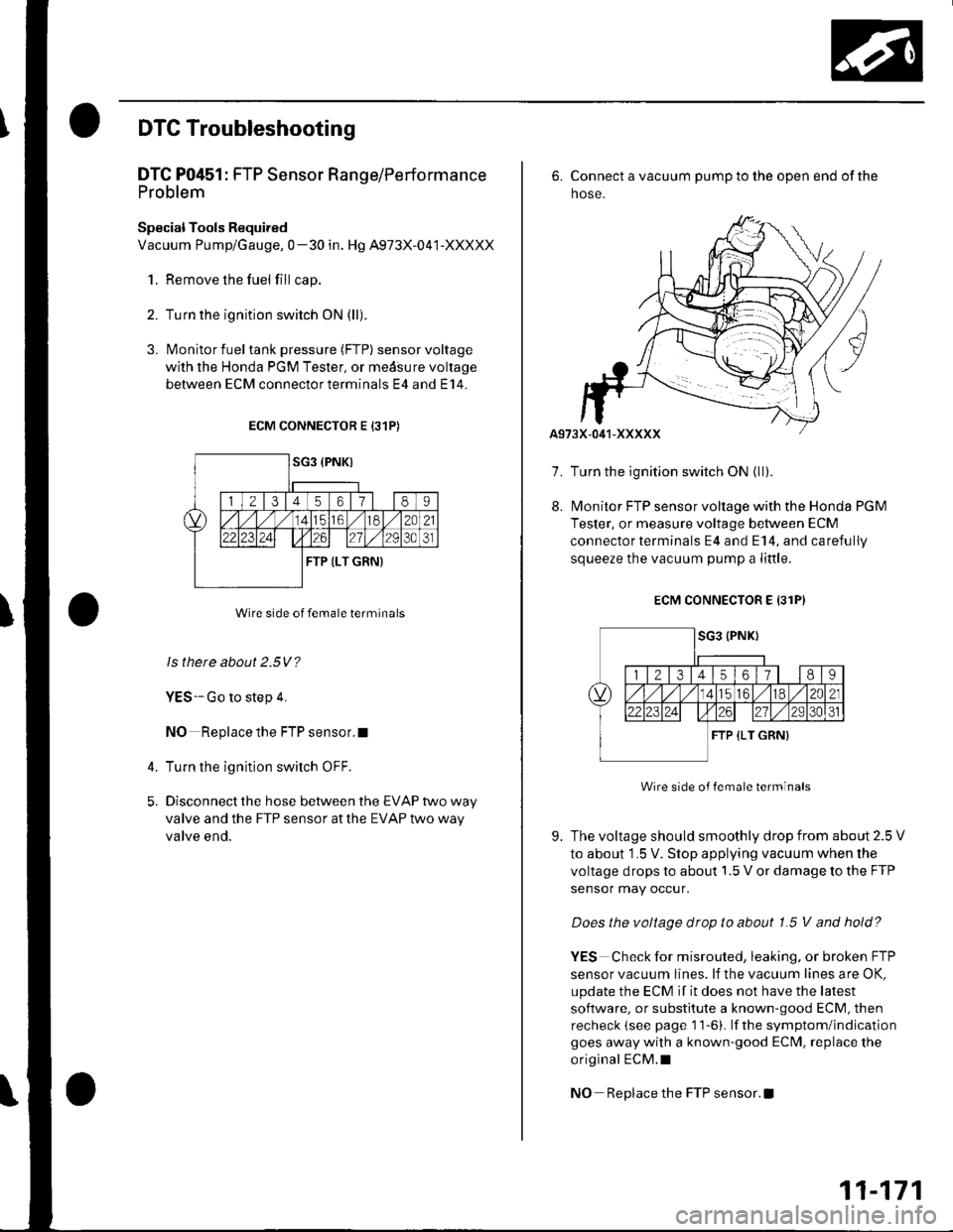
DTC Troubleshooting
DTC P0451: FTP Sensor Range/Performa nce
Problem
Special Tools Required
Vacuum Pump/Gauge, 0-30 in. Hg A973X-041-XXXXX
1. Remove the fuel fill cap.
2. Turn the ignition switch ON (ll)
3. l\4onitor fuel tank pressure (FTP) sensorvoltage
with the Honda PGM Tester, or medsure voltage
between ECM connectorterminals E4 and E14.
ECM CONNECTOR E 131P)
Wire side of female terminals
ls there about 2.5V?
YES-Go to step 4.
NO Replace the FTP sensor.I
Turn the ignition switch OFF.
Disconnect the hose between the EVAP two way
valve and the FTP sensor at the EVAP two way
valve end.
4.
5.
7.
8.
6. Connect a vacuum pump to the open end of the
hose.
Turn the ignition switch ON {ll).
l\4onitor FTP sensor voltage with the Honds PGM
Tester, or measure voltage between ECM
connector terminals E4 and E14, and carefully
squeeze the vacuum pump a little.
ECM CONNECTOR E 13lPI
Wire side of lemale terminals
The voltage should smoothly drop from about 2.5 V
to about 1.5 V. Stop applying vacuum when the
voltage drops to about 1.5 V or damage to the FTP
sensor may occur.
Does the voltage drop to about 1.5 V and hold?
YES Check for misrouted, leaking, or broken FTP
sensor vacuum lines. lf the vacuum lines are OK,
update the ECM if it does not have the latest
software. or substitute a known-good ECM, then
recheck (see page 1 1-6). lf the symptom/indication
goes away with a known-good ECM, replace the
original ECM.I
NO Replace the FTP sensor. !
9.
11-171
Page 379 of 1139
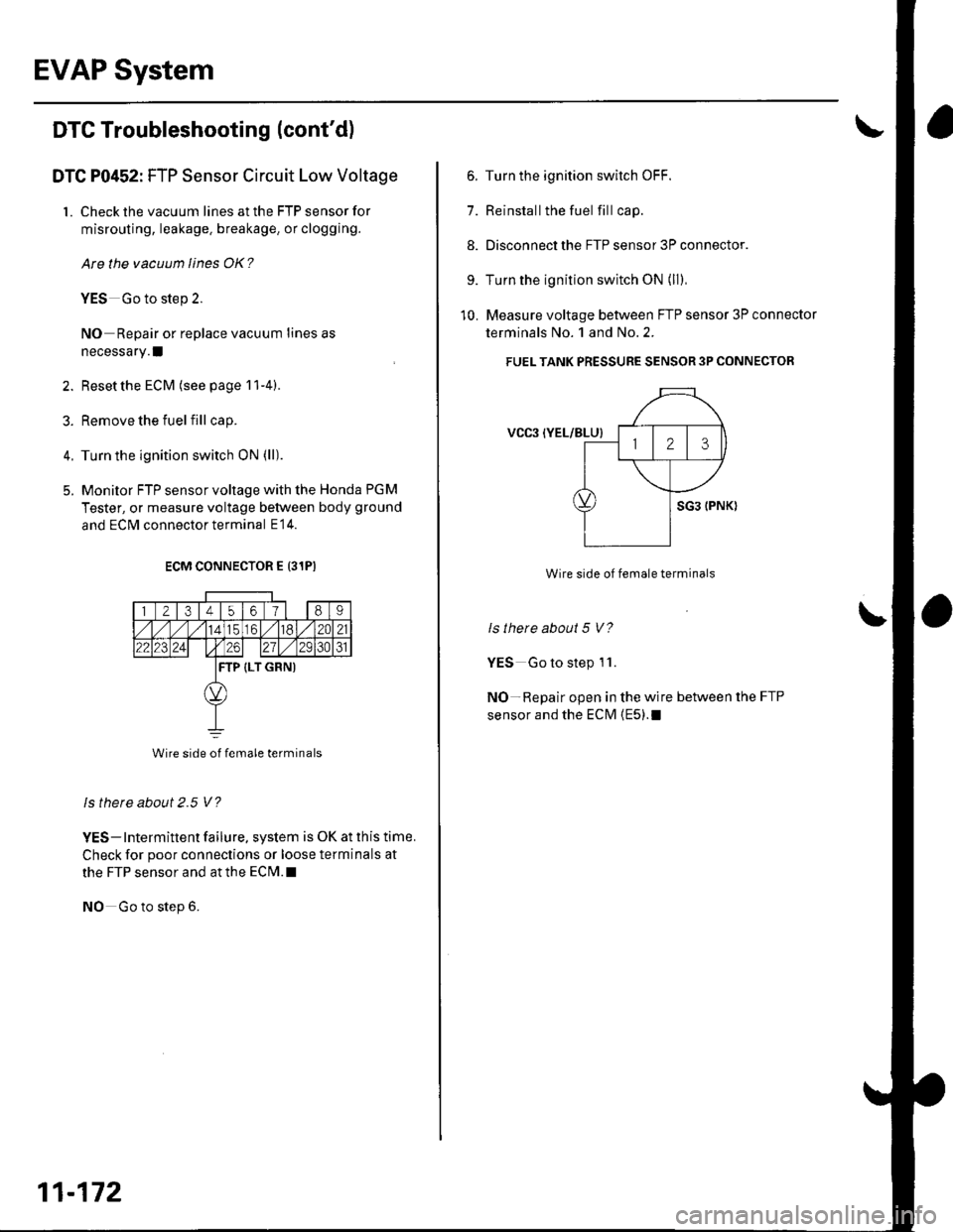
EVAP System
DTC Troubleshooting (cont'd)
DTC P0452: FTP Sensor Circuit Low Voltage
1. Check the vacuum lines at the FTP sensor for
misrouting, leakage. breakage, or clogging.
Are the vacuum lines OK?
YES Go to step 2.
NO Repair or replace vacuum lines as
necessary. I
2. Reset the ECM (see page 11-4).
3. Remove the fuelfill cap.
4. Turn the ignition switch ON (ll)
5. Monitor FTP sensor voltage with the Honda PGM
Tester, or measure voltage between body ground
and ECM connector terminal E14.
ECM CONNECTOR E 131PI
1 2t3t45o/89
././114tc61./182C21
22123241 t26271/ 2931
TP (LT GRN)
Wire side of female terminals
ls thete about 2.5 V?
YES- Intermittent failure, system is OK at this time.
Check for poor connections or loose terminals at
the FTP sensor and at the ECrM.l
NO Go to step 6.
11-172
6. Turn the ignition switch OFF.
7. Reinstallthe fuel fill cap.
8. Disconnect the FTP sensor 3P connector.
9. Turn the ignition switch ON (ll)
10. Measure voltage between FTP sensor 3P connector
terminals No. 1 and No.2.
FUEL TANK PRESSURE SENSOR 3P CONNECTOR
VCgl {YEL/BLU}
Wire side of female terminals
ls there about 5 V?
YES Go to step 1 '1.
NO-Repair open in the wire between the FTP
sensor and the ECM {E5).1