heater HONDA CIVIC 2003 7.G Owner's Manual
[x] Cancel search | Manufacturer: HONDA, Model Year: 2003, Model line: CIVIC, Model: HONDA CIVIC 2003 7.GPages: 1139, PDF Size: 28.19 MB
Page 254 of 1139
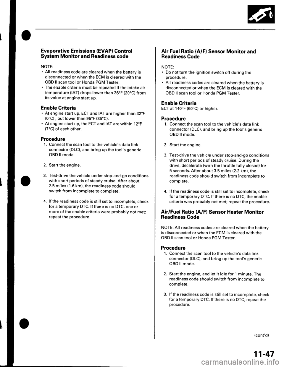
Evaporative Emissions (EVAP) Control
System Monitor and Readiness code
NOTE:
All readiness code are cleared when the batterV is
disconnected or when the ECM is cleared with the
OBD ll scan tool or Honda PGM Tester.
The enable criteria must be repeated if the intake air
temperature (lAT) drops lower than 36'F (20"C) from
its value at engine $an up.
Enable Criteria
At engine start up, ECT and IAT are higher than 32'F(0"C) , but lower than 95'F (35"C).
At engine start up, the ECT and IAT are within 12'F(7'C) of each other.
Procedure
1. Connect the scan tool to the vehicle's data link
connector (DLC), and bring up the tool's generic
OBD ll mode.
2. Start the engine.
3. Test-drive the vehicle under stop-and-go conditions
with short periods of steady cruise. After about
2.5 miles (1.6 km), the readiness code should
switch f rom incomplete to complete.
4. lf the readinesscode isstill setto incomplete, check
for a temporary DTC. lf there is no DTC, one or
more of the enable criteria were probably not met;
repeat the procedure.
Air Fuel Ratio (A/Fl Sensor Monitor and
Readiness Code
NOTE:. Do not turn the ignition switch off during the
orocedure.. All readiness codes are cleared when the baftery is
disconnected or when the ECM is cleared with the
OBD ll scan tool or Honda PGM Tester.
Enable Criteria
ECT at 140'F (60"C) or higher.
Procedure
1. Connect the scan toolto the vehicle's data link
connector (DLC), and bring up the tool's generic
OBD ll mode.
2. Start the engine.
3. Test-drive the vehicle under stop-and-go conditions
with short periods of steady cruise. During the
drive, decelerate (wirh the throttle fully closed) for
5 seconds. After about 3.5 miles (2.2 km). the
readiness code should switch from incomDlete to
complete.
4. lfthereadinesscodeisstill set to incomplete, check
for a temporary DTC. lfthere is no DTC, the enable
criteria was probably not meU repeat the procedure.
Air/Fuel Ratio (A/Fl Sensor Heater Monitor
Readiness Code
NOTE; All readiness codes are cleared when the battery
is disconnected or when the ECM is cleared with the
OBD ll scan tool or Honda PGM Tester,
Procedure'1. Connect the scan tool to the vehicle's data link
connector {DLC), and bring up the tool's generic
OBD ll mode.
2. Start the engine, and let it idle for 1 minute. The
readiness code should switch from incomplete to
comDlete.
3. lf the readiness code is still set to incomplete, check
for a temporary DTC. lf there is no DTC, repeat theproceoure.
(cont'd)
11-47
Page 275 of 1139
PGM-FISystem
3.
DTC Troubleshooting (cont'dl
DTC P0141: Secondary HO2S (Sensor 2l
Heater Circuit Malfunction
1. Reset the ECM (see page 1 l-4)
2. Start the engine.
ls DTC P0141 indicated?
YES-Go to step 3.
NO-lntermittent failure, system is OK at this time.
Check for poor connections or loose terminals at
the secondary HO2S (Sensor 2) and at the ECM.I
Turn the ignition switch OFF.
Disconnect the secondary H02S (Sensor 2) 4P
connecror.
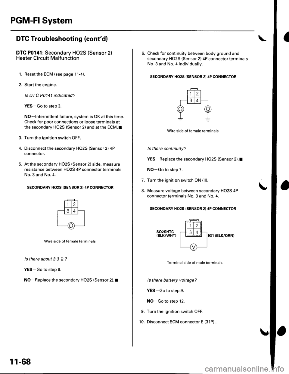
At the secondary HO2S (Sensor 2) side, measure
resistance between H02S 4P connector terminals
No.3 and No. 4.
SECONDARY HO2S (SENSOR 21 4P CONNECTOR
Wire side ol lemale terminals
ls there about 3.3 Q ?
YES Go to step 6.
NO- Replace the secondary HO2S (Sensor 2). t
5.
11-68
6. Check for continuity between body ground and
secondary H02S (Sensor 2) 4P connector terminals
No.3 and No. 4 individually.
SECONDARY HO2S {SENSOR 21 4P CONNECTOR
Wire side of female terminals
ls there continuity?
YES- Replace the secondary HO2S (Sensor 2).1
NO-Go to step 7.
Turn the ignition switch ON (ll).
Measure voltage between secondary H02S 4P
connector terminals No. 3 and No. 4,
SECONDARY HO2S (SENSOR 2l ilP CONNECTOR
t
7.
8.
9.
10.
s02sHTc{BLK/WHTIIG1 (BLK/ORN}
Terminal side of male terminals
ls there battery voltage?
YES Go to step 9.
NO Go to step 12.
Turn the ignition switch OFF.
Disconnect ECM connector E {31P)
Page 277 of 1139
PGM-FI System
DTC Troubleshooting (cont'dl
DTC P0171: Fuel System Too Lean
DTC P0172: Fuel System Too Rich
NOTE: lf some of the DTCS listed below are stored at
the same time as DfC PO17'l and/ot PO172,
troubleshoot those DTCS first, then recheck for P0171
andlot P0112.
P0107, P0108. P1 128. P1 129: Manifold absolute
pressure (MAP) sensor
P1 162. P1 166, P 1 167: 4,,/F sensor (Sensor 1 ) heater
P0137, P0138: Secondary HO2S (Sensor 2)
P014'l: Secondary HO2S (Sensor 2) heater
P1259: VTEC system
1. Check the fuel pressure (see page 11-'145).
ls luel pressure OK?
YES Go to step 2.
NO Check these items:
. lf the pressure is too high, replace the fuel
pressure regulator (see page 11-152).1. lf the pressure istoo low.checkthefuel pump,
the fuel feed pipe, the fuel filter, and replace the
fuel pressure regulator (see page 11-152).I
2. Start the engine. Hold the engine at 3,000 rpm with
no load (in neutral) until the radiator fan comes on.
11-70
3. Turn the ignition switch OFF.
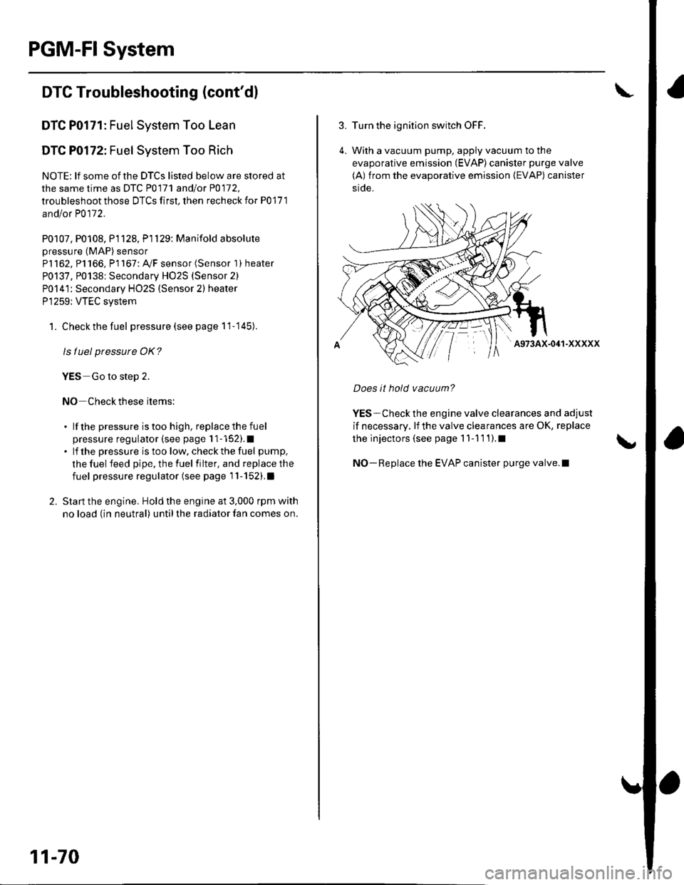
4. With a vacuum pump, apply vacuum to the
evaporative emission (EVAP) canister purge valve
(A) from the evaporative emission (EVAP) canister
side.
' A973AX-041-XXXXX
Does it hold vacuum?
YES-Check the engine valve clearances and adjust
if necessary, lf the valve clearances are OK, replace
the injectors (see page 1 1-1 1 1).1
NO-Replace the EVAP canister purge valve.l
Page 296 of 1139
DTC Pl166: Ay'F Sensor (Sensor 1) Heater
Circuit Malfunction
1. Resetthe ECM (see page 11-4).
2. Start the engine.
ls DTC P1166 indicated?
YES-Go to step 3.
NO-lntermittent failure, system is OK at this lime.
Check for poor connections or loose terminals at
the Ay'F sensor relay, the A,/F sensor (Sensor 1), and
the EcM. !
3. Check the following fuse:
. No. 14 OPTION (30A)fuse in under-hood fuse/
reray Dox.. No. 2*B LAF (Ay'F) HEATER (20A) fuse in under-
dash fuse/relay box.. No. 4 ACG (10A) in underdash fuse/relay box.
Are any of the fuses blown?
YES Repair short in the wire between the Ay'F
sensor relay and the fuses.I
NO Go to step 4.
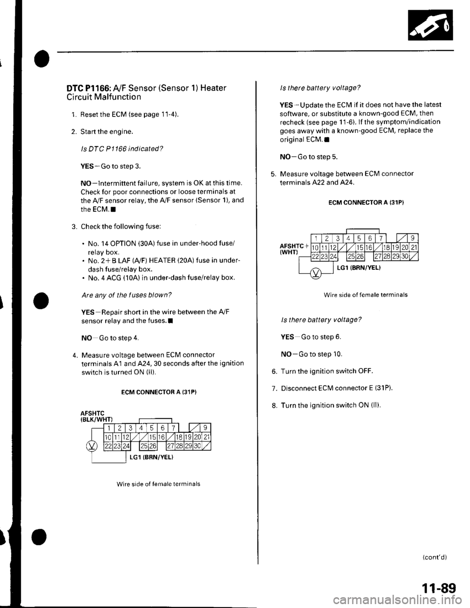
4. Measure voltage between ECM connector
terminals A1 and A24. 30 seconds after the ignition
switch is turned ON (ll).
ECM CONNECTOR A I31P)
Wire srde of lemale terminals
Is therc battery voltage?
YES-Update the ECM if it does not have the latest
soflware, or substitute a known-good ECM. then
recheck (see page 1 1-6). lf the symptom/indication
goes away with a known-good ECM, replace the
original ECM.I
NO-Go to step 5.
5. Measure voltage between ECM connector
terminals A22 and A24.
ECM CONNECTOR A {31P}
Wire side of female terminals
ls there battery voltage?
YES Go to step 6.
NO-Go to step 10.
6. Turn the ignition switch OFF.
7. Disconnect ECM connector E (31P).
8. Turn the ignition switch ON {ll).
(cont'd)
11-89
Page 298 of 1139
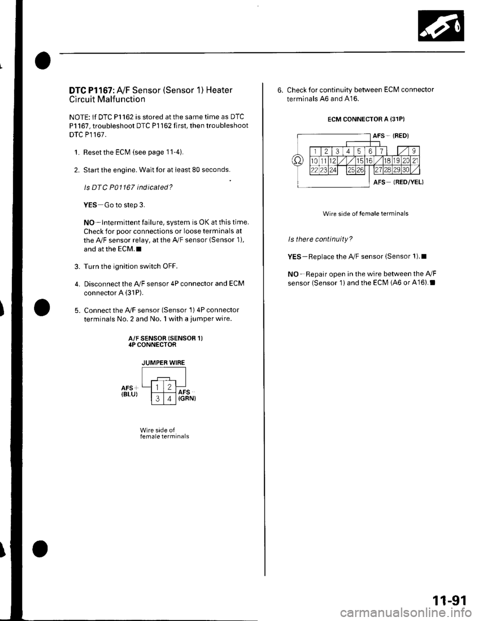
DTC Pl167: Ay'F Sensor (Sensor 1) Heater
Circuit Malfunction
NOTE: lf DTC P1162 is stored at the same time as DTC
P1167, troubleshoot DTC P1162 first, then troubleshoot
DTC P1167.
1. Resetthe ECI\4 (see page 11-4)
2. Start the engine. Wait for at least 80 seconds.
ls DTC P01167 ind icated?
YES Go to step 3.
NO-lntermittent failure, system is OK at this time.
Check for poor connections or loose terminals at
the Ay'F sensor relay, at the Ay'F sensor (Sensor 1),
and at the ECM.I
Turn the ignition switch OFF.
Disconnect the A,/F sensor 4P connector and ECM
connector A (31P).
Connect the Ay'F sensor (Sensor 1) 4P connector
terminals No. 2 and No. 1 with a jumper wire.
?
5.
A/F SENSOR (SENSOR 1)4P CONNECTOR
JUMPER WIRE
Wire side offemale terminals
6. Check for continuity between ECM connector
terminals ,46 and 416.
ECM CONNECTOR A {31P)
AFS- {RED)
trTzTil,ils llt9
t82C21
l?rlzsIels
AFSIRED/YEL)
Wire side of lemale terminals
ls thete continuity?
YES-Replace the A/F sensor (Sensor 1).1
NO-Repair open in the wire between the Ay'F
sensor (Sensor 1 ) and the ECM (46 or A16).I
11-91
Page 345 of 1139
ldle Control System
ldle Speed lnspection
NOTE:' Leave the idle air control (lAC) valve connecled.. Before checking the idle speed, check these items:- The malfunction indicator lamp (MlL) has not been
reported on.- lgnition timing- Spark plugs- Air cleaner- PCV system. Pullthe parking brake lever up. Start the engine, and
make sure the headlights are off.
1. Disconnect the evaporative emission (EVAP)
canister purge valve 2P connector.
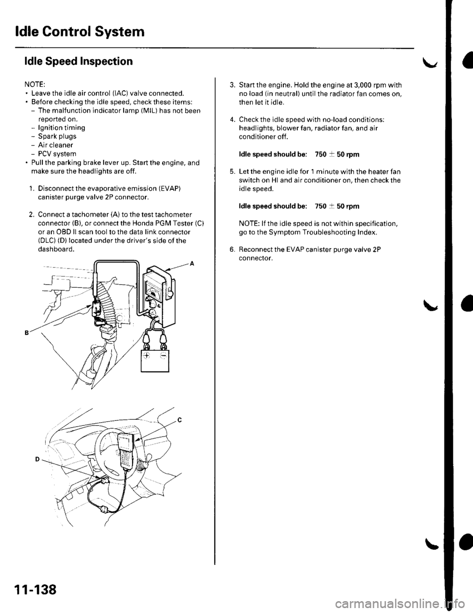
2. Connect a tachometer (A)to the test tachometer
connector (B), or connect the Honda PGM Tester (C)
or an OBD ll scan tool to the data link connector(DLC) (D) located under the driver's side of the
dashboard.
11-138
4.
3.
5.
6.
Start the engine. Hold the engine at 3,000 rpm with
no load (in neutral) until the radiator fan comes on,
then let it idle.
Check the idle speed with no-load conditions;
headlights, blower fan, radiator fan, and air
conditioner off.
ldle speed should be: 750 t 50 rpm
Let the engine idle for 1 minute with the heater fan
switch on Hl and air conditioner on, then check the
idle speed.
ldle speed should be: 750 t 50 rpm
NOTE: lf the idle speed is not wilhin specification,
go to the Symptom Troubleshooting Index,
Reconnect the EVAP canister purge valve 2P
connector.
Page 374 of 1139
Catalytic Converter System
DTC Troubleshooting
DTC P0420: Catalytic System Efficiency
Below Threshold
NOTE: lf some of the DTCS listed below are stored at
the same time as DTC P0420, troubleshoot those DTCS
first, then recheck for DTC P0420.
P0137, P0138: Secondary Heated Oxygen Sensor(secondary HO2S) (Sensor 2)
P0141: Secondary HO2S (Sensor 2) heater
1. Reset the ECM {see page 1'l-4}, then continue to
step 2 through 5 to reset the readiness code.
2. Start the engine. Hold the engine at 3,000 rpm with
no load (in neutral) untilthe radiator fan comes on.
Drive for about l0 minutes without stopping. Your
speeo can vary.
With the transmission in 4th gear, drive at a steady
speed between 50 62 mph (80-'100 km/h) for
30 seconds.
Repeat step 4 three times. Between each repetition,
close the throttle completely for 1 2 seconds. lf
the engine is stopped during this part of the
procedure, repeat steps 3, 4 and 5.
Check for a Temporary DTC with the scan tool.
Does the scan tool indicate Temporaty DTC
P0420?
YES Check the TWC. lf necessary, replace the
TWC.I
NO Check for readiness code completion. lfthe
readiness is complete, it was a interminent failure,
and the system is OK at this time. lf the readiness
code is incomplete, repeat steps 2 through 5.1
4.
11-167
Page 543 of 1139
EPS Components
Steering Gearbox Removal (cont'd)
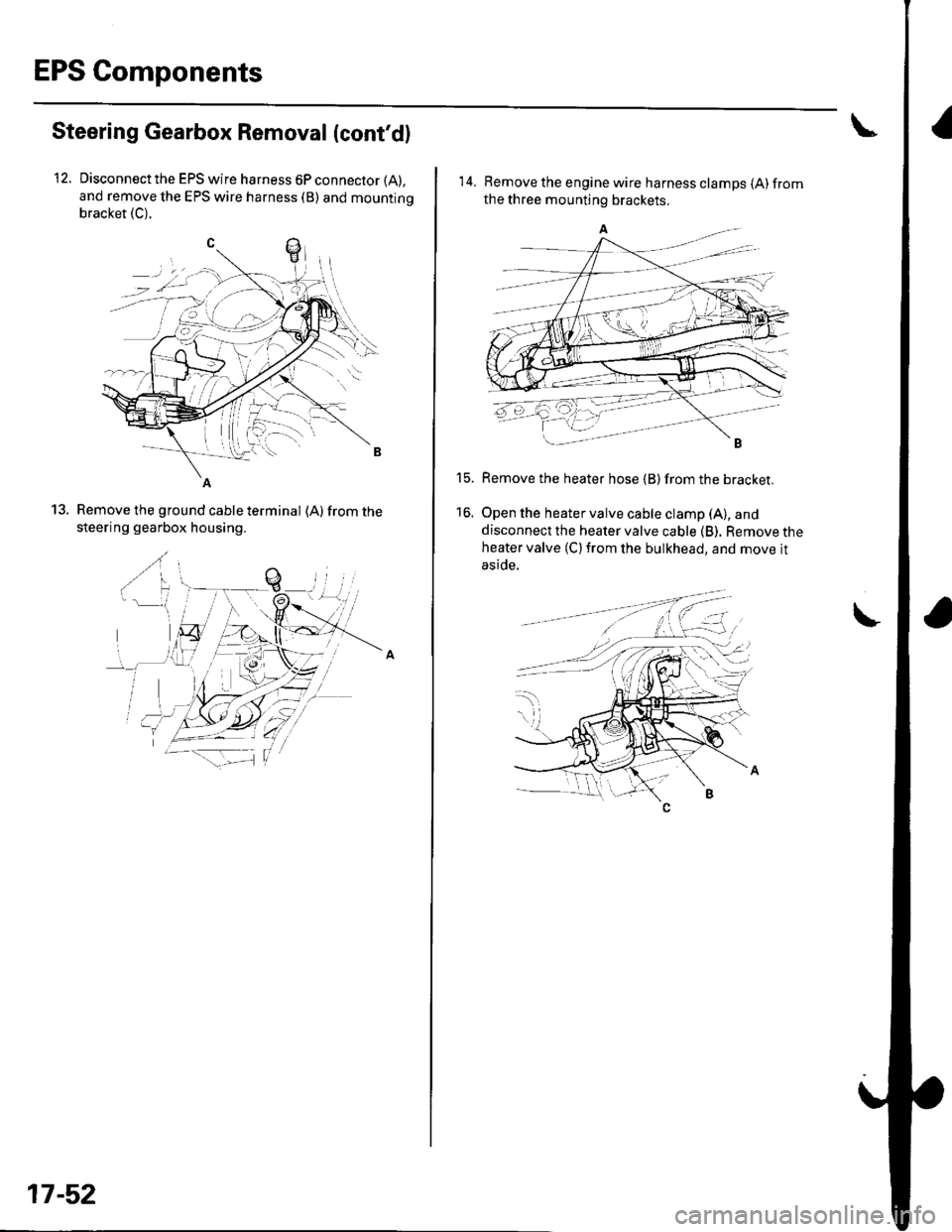
Disconnect the EPS wire harness 6P connector (A),
and remove the EPS wire harness (B) and mountino
bracket (C).
12.
Remove the ground cable terminal (A) from the
steering gearbox housing.
..(
.,/ a
b-H\
ry T,-.lt'^ \
'" \--
13.
_-1..1.-'
-a--zii F--_1
17-52
14. Remove the engine wire harness clamps {A)fromthe three mounting brackets.
Remove the heater hose {B) from the bracket.
Open the heater valve cable clamp (A), and
disconnect the heater valve cable (B). Remove theheater valve (C) from the bulkhead, and move jt
aside.
t5.
16.
I
Page 555 of 1139
EPS Components
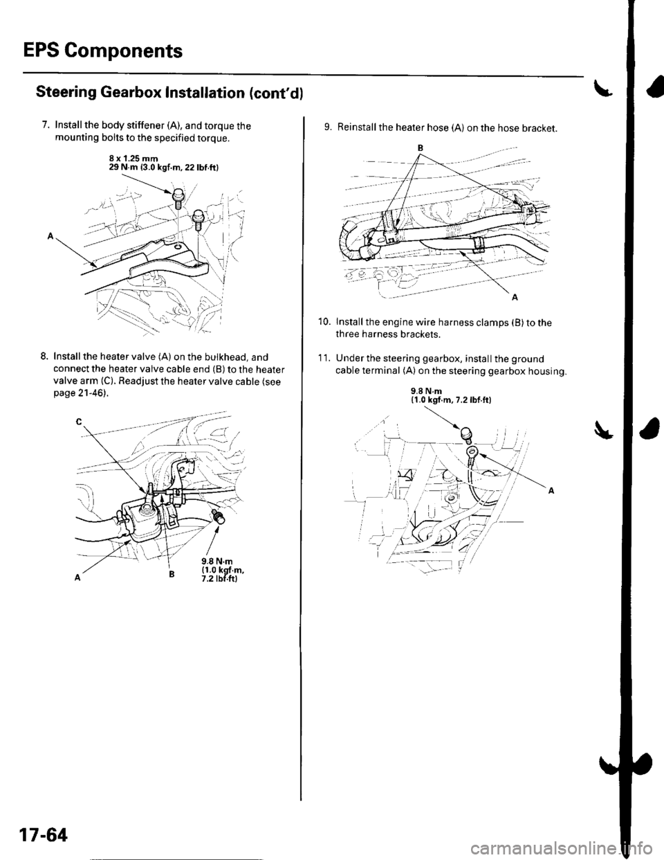
Steering Gearbox Installation (cont'd)
7. Installthe body stiffener (A), and torque the
mounting bolts to the specified torque.
8 x 1.25 mm29 N.m {3.0 kgf.m,22lbf.ftl
LInstall the heater valve (A) on the bulkhead, and
connect the heater valve cable end (B) to the heater
valve arm (C). Readjust the heater valve cable {seepage 21-46).
9.8 N.m(1.0 kgf m,7.2 tbf.ftl
L-t ,:.i.t'
17-64
9. Reinstall the heater hose (A) on the hose bracket.
Install the engine wire harness clamps (B) to the
three harness brackets.
Under the steering gearbox, install the ground
cable terminal (A) on the steering gearbox housing.
10.
'I t.
9.8 N.m{1.0 kgf.m, 7.2lbf.ft)
Page 669 of 1139
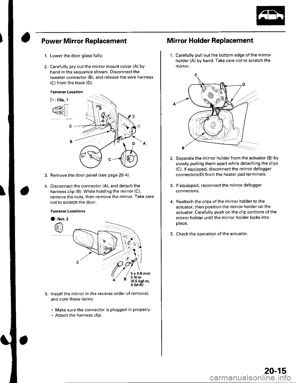
Power Mirror Replacement
1.
2.
5.
Lower the door glass fully.
Carefully pry out the mirror mount cover (A) by
hand in the sequence shown. Disconnect the
tweeter connector (B), and release the wire harness
(C) from the hook (D).
Fastener Location
) : Clip, 1
3. Remove the door panel (seepage20-4).
4. Disconnectthe connector (A), and detach the
harness clip (B). While holding the mirror {C),
remove the nuts, then remove the mirror. Take care
not to scratch the door.
Fastener Locrtions
O: Nut.3
lnstall the mirror in the reverse order of removal,
and note these items:
. Make sure the connector is plugged in properly.
. Attach the harness clip.
Mirror Holder Replacement
1. Carefully pulloutthe bottom edge ofthe mirror
holder (A) by hand. Take care not to scratch the
mrrror.
5.
Separate the mirror holder from the actuator (B) by
slowly pulling them apart while detaching the clips
(C). lf equipped, disconnect the mirror defogger
connectors{D) from the heater pad terminals.
lf equipped, reconnect the mirror defogger
connectors.
Reattach the clips of the mirror holder to the
actuator, then position the mirror holder on the
actuator. Carefully push on the clip portions of the
mirror holder untilthe mirror holder locks into
prace.
Check the operation of the actuator
20-15