heater HONDA CIVIC 2003 7.G Repair Manual
[x] Cancel search | Manufacturer: HONDA, Model Year: 2003, Model line: CIVIC, Model: HONDA CIVIC 2003 7.GPages: 1139, PDF Size: 28.19 MB
Page 879 of 1139
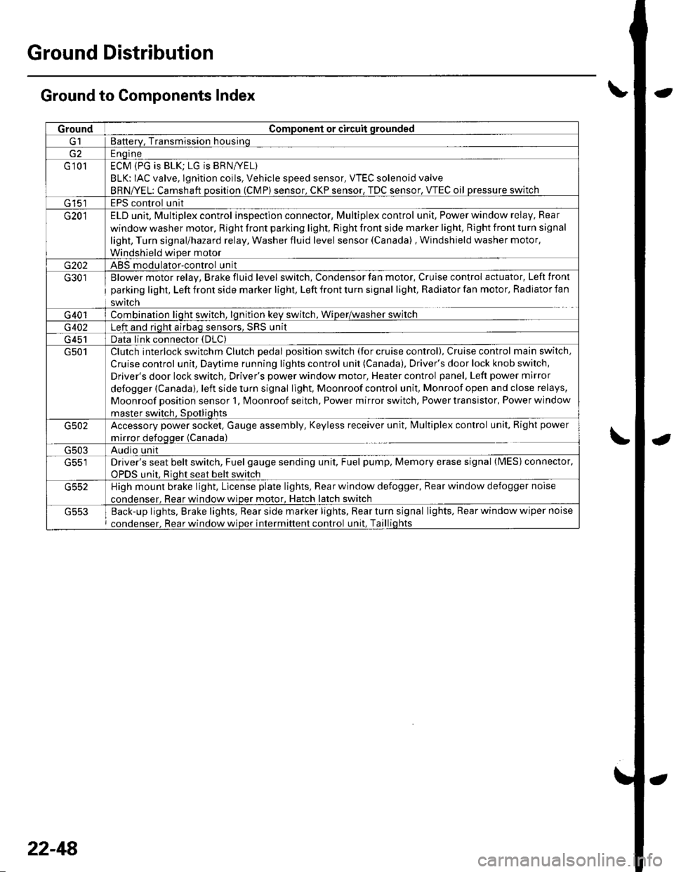
Ground Distribution
Ground to Components Index
GroundComponent or circuit qrounded
Batterv, Transmission housinq
E ngine
G 101ECM (PG is BLK; LG is BRN/YEL)
BLK: IAC valve, lgnition coils, Vehicle speed sensor, VTEC solenoid valve
BRNA/EL: Camshaft oosition (CMP) sensor. CKP sensor, TDC sensor. VTEC oil pressure switch
G 15'�]EPS control unit
G201ELD unit. Multiplex control inspection connector, Multiplex control unit, Power window relay, Rear
window washer motor, Right front parking light, Right front side marker light, Right front turn signal
light, Turn signal/hazard relay, Washer fluid level sensor (Canada) , Windshield washer motor,
Windshield wiDer motor
G202ABS modulator-control unit
G301
G401
Blower motor relay, Brake fluid level switch, Condensor fan motor, Cruise control actuator, Left front
parking light, Left front side marker light, Left front turn signal light, Radiator fan motor, Radiator fan
swrtcn
Combination liqht switch, lqnitlon kev srvitch, Wiper/wasfrer sr,virch
G402Left and riqht airbaq sensors, SRS unit
G 451Data link connector (DLC)
G501Clutch interlock switchm Clutch pedal position switch (for cruise control), Cruise control main switch,
Cruise control unit, Daytime running lights control unit (Canada), Driver's door lock knob switch,
Driver's door lock switch, Driver's power window motor, Heater control panel, Left power mirror
defogger (Canada), left side turn signal light, Moonroof control unit, Monroof open and close relays,
Moonroof position sensor '1, Moonroof seitch, Power mirror switch, Power transistor, Power window
master switch. SDotliqhts
G502Accessory power socket, Gauge assembly, Keyless receiver unit, lvlultiplex control unit, Right power
mirror defogger {Canada)
G503Audio unit
G551Driver's seat belt switch, Fuel gauge sending unit, Fuel pump, Memory erase signal (IMES) connector,
OPDS unit. Rioht seat belt switch
G552High mount brake light, License plate lights, Rear window defogger, Rear window defogger noise
condenser. Rear window wioer motor, Hatch latch switch
Back-up lights, Brake lights, Rear side marker lights, Rear turn signal lights, Rear window wiper noise
condenser, Rear window wiper intermittent control unit, Taillights
22-48
Page 931 of 1139
Audio System
Audio Unit Removal/lnstallation
NOTE:. Put on gloves to protect your hands.. Take care not to scratch the dashboard and relatedpa rts.
1. Make sure you have the anti-theft code for the radio,
then write down the frequencies for the radio's
preset buttons.
2. Remove the driver's dashboard lower cover (see
page 20-59).
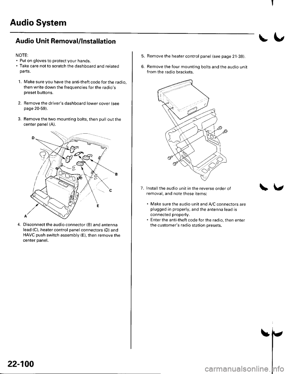
3. Remove the two mounting bolts, then pull out the
center panel (A).
4.Disconnect the audio connector (B) and antenna
lead (C), heater control panel connectors (D) and
HAVC push switch assembly (E), then remove the
center panel.
22-100
!\,
7.
Remove the heater control panel (see page 21 38).
Remove the four mounting bolts and the audio unit
from the radio brackets.
Installthe audio unit in the reverse order of
removal, and note these items:
. Make sure the audio unit and A/C connectors areplugged in properly, and the antenna lead is
connected properly.. Enter the anti-theft code for the radio, then enter
the customer's radio station presets.
\v
I
Page 935 of 1139
Rear Window Defogger
J
I
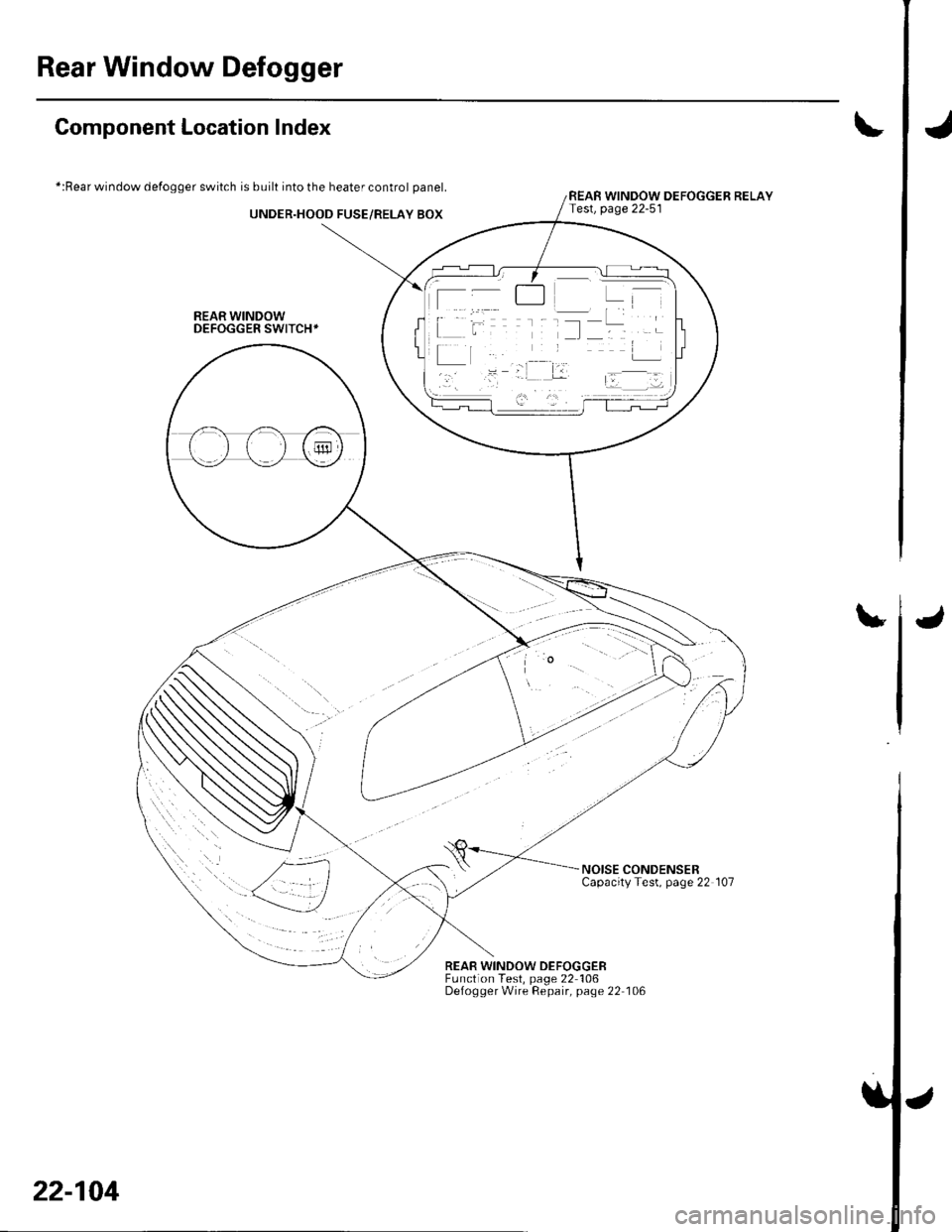
Component Location Index
*:Rear window defogger switch is built into the heater control panel.
UNDER.HOOD FUSE/RELAY BOX
REAR WINDOWDEFOGGER SWITCH+
t
REAR WINDOW DEFOGGER RELAYTest, page 22-51
u
NOISE CONDENSERCapacityTest, page 22 107
REAR WINDOW DEFOGGEBFunction Test, page 22 106Defogger Wire Repair, page 22 106
22-104
J
Page 937 of 1139
Rear Window Defogger
Function Test
NOTE:. Be careful not to scratch or damage the defogger
wires with the tester probe.
. Before testing, check the No. 11 (30A) fuse in the
under-hood fuse/relay box and No. '14 ('10A) fuse in
the under-dash fuse/relay box.
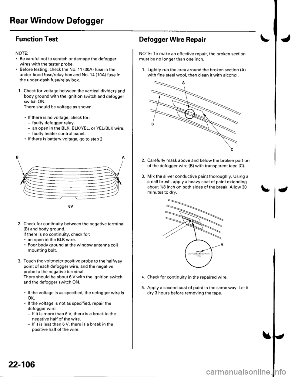
1. Check for voltage between the ve rtica I dividersand
body ground with the ignition switch and defogger
switch ON.
There should be voltage as shown.
. lf there is no voltage. checkfor:- faulty defogger relay.- an open in the BLK, BLK,/YEL, or YEL/BLK wire.- taulty heater control panel.
. lf there is battery voltage, goto step 2.
6V
Check for continuity between the negative terminal(B) and body ground.
lf there is no continuity, check for:. an open in the BLK wire.. Poor body ground at the window antenna coil
mounting bolt.
Touch the voltmeter positive probe to the halfway
point of each defogger wire. and the negative
probe to the negative terminal,
There should be about 6 V with the ignition switch
and the defogger switch ON.
. lf thevoltage is asspecified, the defoggerwlre is
oK.. lf the voltage is not as specified, repair the
defogger wire.- lf it is more than 6 V, there is a break in the
negative half of the wire.- lf it is less than 6 V, there is a break in the
positive half of the wire.
2.
22-106
2.
Defogger Wire Repair
NOTE: To make an effective repair, the broken section
must be no longer than one inch.
1. Lightly rub the area around the broken section (A)
with fine steel wool, then clean it with alcohol.
Carefully mask above and below the broken portion
of the defogger wire (B) with transparent tape {C).
Mix the silver conductive paint thoroughly. Using a
small brush, apply a heavy coat of paint extending
about 1/8 inch on both sides of the break. Allow 30
minutes to dry.
Check for continuity in the repaired wire.
Apply a second coat of paint in the same way. Let it
dry 3 hours before removing the tape.
5.
Page 1026 of 1139
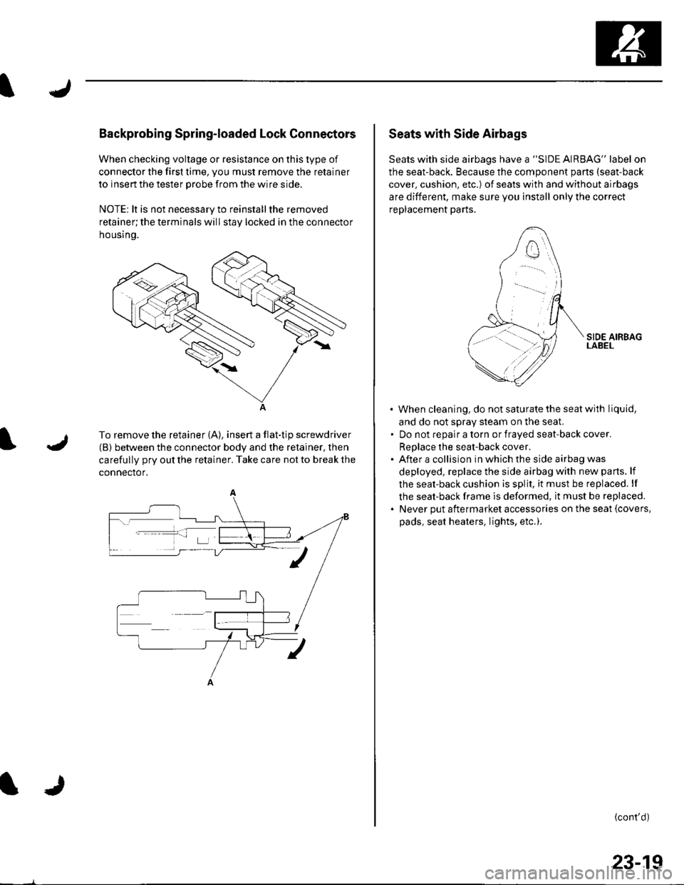
Backprobing Spring-loaded Lock Connectors
When checking voltage or resistance on this type of
connector the first time, you must remove the retainer
to insert the tester orobe from the wire side.
NOTE: lt is not necessary to reinstall the removed
retainer;the terminals will stay locked in the connector
housrno.
A
To remove the retainer (A), insert a flat-tip screwdriver
(B) between the connector body and the retainer, then
carefully pry out the retainer. Take care not to break the
connector.
Seats with Side Airbags
Seats with side airbags have a "SIDE AIRBAG" label on
the seat-back. Because the component pans (seat-back
cover, cushion, etc.) of seats with and without airbags
are different, make sure you install only the correct
replacement parts.
When cleaning, do notsaturatethe seatwith liquid,
and do not sDrav steam on the seal
Do not reoalr a torn or fraved seat-back cover.
ReDlace the seat-back cover.
After a collision in which the side airbag was
deployed, replace the side airbag with new parts. lf
the seat-back cushion is split, it must be replaced. lf
the seat-back frame is deformed, it must be replaced.
Never put aftermarket accessories on the seat {covers,
pads, seat heaters, lights, etc.).
(cont'd)
23-19
Page 1135 of 1139
)
Orive BehInspecaron................ 4-26
Door PanelsRemoval/lnstallation -............................. 20-4
Door Sash TrimRep1acement......................................... 20 10
Door StrikersAdiustment ........................................... 20-13
Door Weatherst psBeplacement...........-............................. 20 1 1
EPS Conirol UnitRemoval/1nsta11ation ..................-......... 17-67
EPS Indicator CircuitTroubleshooting ................................... 17 -47
EPS MotorRemoval/lnstallation .-.......................... 17-49
EVAP CanisterRep1acement......................... ......... 11,189
EVAP Control Syst€mComponentLocation Index ..............'11-170
EVAP Two-Wey ValveTest ..........-.............-............................ 11 186
Evaporetor CoreRep1acement........................ . ... 21-42
Evaporator Tomperature SensorReplacement......................................... 21 -37Test..................................... ..........2137
EvaporrtoFHeater UnitReplacement........................................ 21 43
Exhaust ManifoldRemoval/1nsta11ation ................................ I 7
Exhaust Pipe8ep|acement............................................. 9-8
Front SpeakersRep|acement....................................... 22-102
Front SuspensionComponentLocation Index................... 18-3
Fueland EmissionsDescription ........................................... 11-12
Fuel Fill DoorAdjustment ..........-................................ 20 93
Fuel Fill Door OpenetBeplacement........................ . ............ 20.109
Fuel Fill Door Opener CableReplacement....................................... 20- lO7
Fuel FilterReplacement....................................... 1 1-152
Fuel Gauge Sending UnitTest ......................-.-..........-.................. 11'156
Fuel Injection Syslem (PGM"FIlComponent Location 1ndex................. 11-49
Fuel IniectorsRep1acemen1....................................... 1 1 1 1 l
Fuel Lines and HosesInspection .......................................... 1 1'146Removal ....................... . .. . .... 11-149Insta|1ation .......................................... 1 1 150
FuelPipe ProtectolReplacement....................................... 20-104
Fuel Pressure RegulatotReplacement....................................... 1 1-152
Fuel Pulsation DamperReplacemenl................................... 11 154
Fuel PumpReplacement,,,,,.,.,.,,,.,,,,,,,,,,,,.,.,.,,,..,.. 11-153
Fuel Pump CircuitTroubleshooting -.......-....................... 1 1-141
FuelSupply SystemComponent Location lndex .............. 11 140Adjustment................................... 11-144Test........-...-................. ... ............- 11-145
FuelTankBeplacemenl.............. . ..... .. 11 155
Fuel Tank Vapor ControlValveTest ......................-....... ... . . 11-187Replacement,,.,,...,.,,,.,.,,,,... .. .. 11 189
Fuses{See first page ofthis Index)
)
Rep|acement................. ..................... 4 26
Drive Belt Auto-tensionellnspection ............................................... 4 21Rep1acement.................................... ..4-28
Driver's PocketRemoval/lnstallation -........................... 20-60
Driver's TrayRemoval/lnstallation .........................-.- 20-65
DRL {Daytime Running LightslControl Unitlnput Test .................... ........ . . . ......22-16
DTCs(See first page olthis Index)
Dust and Pollen FillerReplacement......................................... 21-39
Dynamic Damper, DriveshaftsReplacement........................................... 16-8
ECT SensorReplacement.,.,,,.,.,,,,,,,,,,,,,,................ 1 1-1 14
El€ctrical Power Steering IEPS)Signal CircuitTroubleshooting ........ ... .. 11-135
EmblemsReplacement......................-................ 20-100
Engine AssemblyRemova1 .................................................... 5 2Installation ............._.................................. 5-9
Engine Block AssemblyComponent Location Inder ..................... 7.3
Engine Block, BareInspect|onRepair
Fan ControlsComponent Location Index................. 10'l 1Circuit Diagram .. ..... . .. . .................. 10 13
Fender Fairing, FrontReplacement...-................................... 20-103
Final Driven Gear. M/TReplacement.... . . ................................ 13-53
FrameRepair Chan............ ... ....................... 20 11 4
Frame StiffenelReplacement......-................................ 20- J'13
Front ConsoleRemoval/lnstallation ............................ 20 5lDisassembJy/Reassemb|y ................... 20 58
Front DoorsComponent Location Index................... 20-2Adiustment ........................................... 20.12
Front Driveshaft AssemblyInspeclion .................... ... ....16 3Remova1...................-...... ... .....16-3Disassembly ............................... .....165Resassemb|y ................................-......... 16-9Insta11arion ........................ ...... ............ l6 17
Front lmpact SensorsRep1acement............................ ...23 125
................7-15................1 11
)
Entry Light Control SystemComponent Location Index ...............-. 22-89Circuit Dia9ram .................................... 22 90
EPS ComponentsComponent Location 1ndex..........-...... 17-!7Description ........................ ...... ..17-24Circuit Diagram11 26(cont'd)
Page 1136 of 1139
Service Manual Index
(cont'dl
Gauge A3semblyReplacement......................................... 22 64
Gaug€sComponent Location Index ..........-...... 22 54How-to lnformation ........................22-56Circuit Diagram22-54
Heater Valve CableAdjustment ...................... .................... ?1-46
High Mount Brake Light8ep|acement......................................... 22 82
Hood
lmmobilizer SystemComponent Location In dex .............. 22-162
\
G
Description
Genoral Information(See seclion 1)
Glove BoxRemoval/1nsta11ation .......................-.... 20-63
GrilleReplacement...........-............................. 20-94
Hood lnsulatorReplacement......................................... 20-89
Hood LatchRep1acement................... ..........20 108
Hood Opener CableComponentLocation Index ..............20 105Replacement ................ . . ........... .....20 106
Hood SealBeplacement.-...........................-........... 20-88
HornTesVReplacement . . ................ ...... 22-122
CircuitDiagram ...........................22-164Troubleshooting ............................ 22,165
Inner Fender, FronlRepf acemenl....................................... 20-102
Inside Rearview MirrorReplacement..........-.............................. 20 16
Instrument PanelRemoval/1nsta11ation................. ....... 20-59
Intake Air Bypass ControlThermal ValveTesr................................ ..... ..11-161
Intake Air SystemComponent Location Index ...-.-........ 11-159
Intake ManitoldRemoval/1nsta11ation ................................ I 2
lntermediate Shaft AssemblyRemova1 ................-.-...-......................... 16-19Disassemb|y................... ... ......-.... 16,20Resassemb|y ........................................ 16 22Installation .........-...-.............................. 16-24
Keyless Entry Transmitter
Adjuslment
H
Adiustment .......
Hatch Handle
Horn SwitchTest ............-........
HornsComponent Location IndexCirc!it Diagram
H02S. SecondaryReplacement
..............22-120Replacement
22-122
22 12120-110
20-'110Hatch LatchReplacement$
K
Hatch Latch Switch
.... 11 113
HubsReplacement. ... .................................. 1A 26Test
Test
Replacement
Hatch Support StrutsBeplacement.....
Hatch WeatherstrioReplacement....
Hazard Warning Switchtest
ldle ControlSystemComponentLocation Index .............. 11-129Inspection,.,.........-.......,.,.,,,,,,.,,,.,.,..... 1'l 138
lgnition CoillslBemoval/lnstallation ...............-.............. 4 18
22-161Test ...................................................... 22 161
Keyless Entry/Security Alarm SystemComponenl Location Index .............. 22 150Circuil Diagram ................. . .............. 22 151
Keyless Receiver Unitlnput Test ............................................ 22-153
Knock SensorReplacement......-................................ 1 1 115
KnucklesReplacementFront Suspensron ............................. 18-1 1Rear Suspension ........ .................-... 18-28
Repair ...............
H.tch Lock Actuator22-159
Hatch Lock CylinderRep|acement....................................... 20,111
Hatch SpoilerIAT {lntake Air Temperature} SensorReplacement.,.........-...'11 115
20-91
20-92
.................... 22_88lgnition Key LightTest,,.,,,,.,...,......-.
H6adlightAdjustmentlgnition Key Switch
....................... 22-91
....................... 22-91..22-78TestReQ\ace$entlgnition SwitchTest .,,,.,.,.,,,,.,.,.......22-53License Plate LightReplacement...........-... - ... .....22-83
License TrimReplacement..................-...-..........-....... 20-98
Lights, ExteriorComponent Localion Index.................22 68
Lights,InteriorComponent Location Index................. 22-94CircuitDiagram .. .. ...... .... 22-95
HcadlightsCircuit Diagram .............................. 22-71, 72
HeadlinerRemoval/lnstallalion ............................ 20-54
Heater ControlPanelRemoval/1nsta11ation ............................ 21-38
Heater Control Power and Ground CircuitsTroubfeshooting......... .......................21-27
lgnition SystemComponent Location Index ................... 4-15CircuitDia9ram .................................... 4'161nspection ............................................... 4-17
lmmobilizer Control Unit-Receiver
J
22-161