HONDA CIVIC 2003 7.G Workshop Manual
Manufacturer: HONDA, Model Year: 2003, Model line: CIVIC, Model: HONDA CIVIC 2003 7.GPages: 1139, PDF Size: 28.19 MB
Page 341 of 1139
ldle Gontrol System
't.
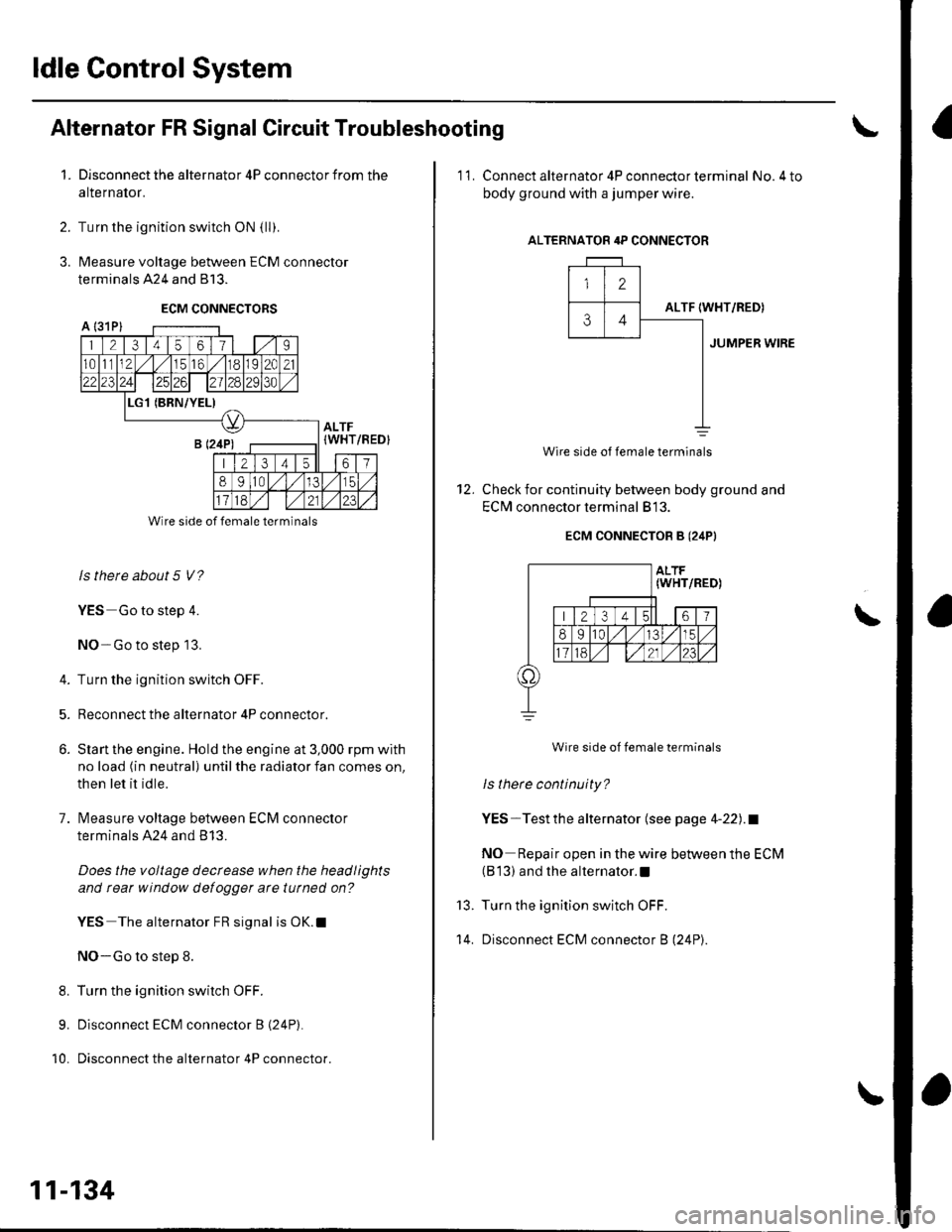
Alternator FR Signal Circuit Troubleshooting
Disconnect the alternator 4P connector from the
alternalor.
Turn the ignition switch ON {ll).
Measure voltage between ECM connector
terminals 424 and 813.
ECM CONNECTORS
2.
3.
A l31Pl
1 21345611 | 1.,'I
1011112,/56,/r8119l2C21
2312428129130
L(BRN/YEL)
ALTF(WHT
213 4t561
89ltal,/l/15
Wire side of female terminals
ls there about 5 V?
YES Go to step 4.
NO-Go to step 13.
4. Turn the ignition switch OFF.
5. Reconnect the alternator 4P connector.
6. Slan the engine. Hold the engine at 3,000 rpm with
no load (in neutral) until the radiator fan comes on,
then let it idle.
7. lvleasure voltage between ECM connector
terminals A24 and B 13.
Does the voltage decrease when the headlights
and rear window defogger arc tutned on?
YES The alternator FR signal is OK.l
NO-Go to step 8.
8. Turn the ignition switch OFF.
9. Disconnect ECM connector B (24P).
10. Disconnect the alternator 4P connector.
/REDI
11-134
'11. Connect alternator 4P con necto r term inal No.4 to
body ground with a jumper wire.
ALTERNATOR 4P CONNECTOR
12
ALTF34IWHT/RED)
JUMPER WIRE
12.
Wire side of female terminals
Check for continuity between body ground and
EClvl connector terminal 813.
ECM CONNECTOB B (24PI
Wire side of female terminals
ls there continuity?
YES-Testthe alternator (see page 4-22).1
NO Repair open in the wire between the ECM(B 13) and the alternator.l
Turn the ignition switch OFF.
Disconnect ECM connector B (24P).
\
13.
't 4.
Page 342 of 1139
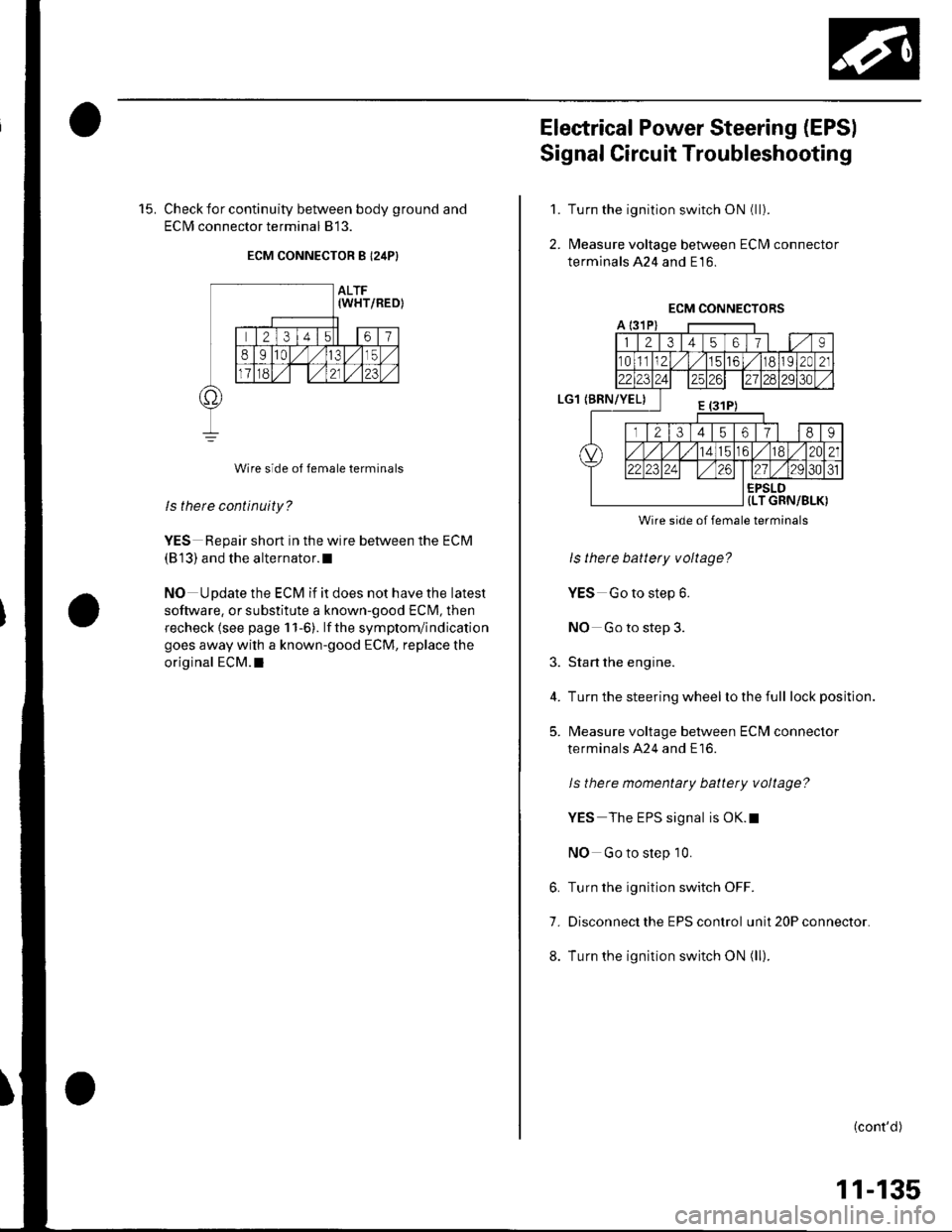
15. Check for continuity between body ground and
ECIM connector terminal 813.
ECM CONNECTOR B I24P}
Wire side of female terminals
ls there continuity?
YES Repair short in the wire between the ECM
(813) and the alternator.l
NO Update the ECM if it does not have the latest
software, or substitute a known-good ECM, then
recheck lsee page 1 1-6). lf the symptom/indication
goes away with a known-good ECM, replace the
original ECM.I
Electrical Power Steering (EPSI
Signal Circuit Troubleshooting
Turn the ignition switch ON (ll).
l\4easure voltage between ECM connector
terminals 424 and E16.
1.
2.
3.
4.
5.
Wire side of female terminals
ls there battery voltage?
YES Go to step 6.
NO Go to step 3.
Start the engine.
Turn the steering wheel lo the full lock position.
l\4easure voltage between ECM connector
terminals A24 and E16.
ls there momentaty battery voltage?
YES The EPS signal is OK.t
NO Go to step 10.
6. Turn the ignition switch OFF.
7. Disconnect the EPS control unit 20P connector.
8. Turn the ignition switch ON (ll).
(cont'd)
11-135
Page 343 of 1139
ldle Control System
Electrical Power Steering (EPSI Signal Circuit Troubleshooting (cont'd)
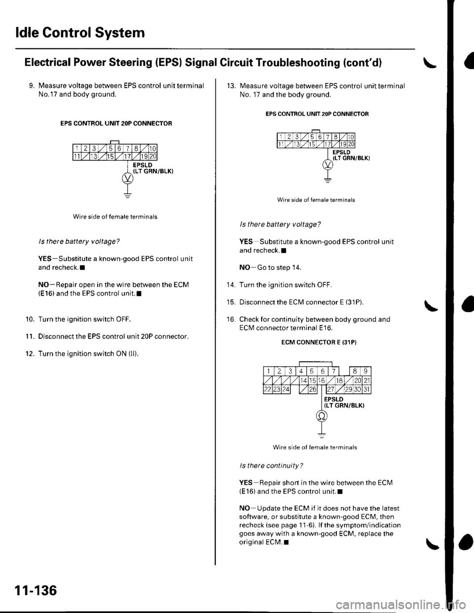
9. Measure voltage between EPS control unitterminal
No.l7 and body ground.
EPS CONTROL UNIT 2OP CONNECTOR
Wire side of female terminals
ls there battety voltage?
YES-Substitute a known-good EPS control unit
and recheck.I
NO- Repair open in the wire between the ECM(E 16) and the EPS control unit.l
Turn the ignition switch OFF.
Disconnect the EPS control unit 20P connector.
Turn the ignition switch ON (ll).
10.
I '�I.
12.
11-136
'13. l\4easure voltage between EPS control unitterminal
No. 17 and the body ground.
EPS CONTROL UNIT 2OP CONNECTOR
Wire side of female terminals
ls there battery voltage?
YES Substitute a known-good EPS control unit
and recheck.l
NO-Go to step 14,
Turn the ignition switch OFF.
Disconnectthe ECM connector E {31P).
Check for continuity between body ground and
ECI\4 connector terminal E16.
ECM CONNECTOR E {31PI
14.
t5_
16.
12345617l 189
56./182A21
2223zi ./29 30ol
EPSLD{LT GRN/BLK)
a,
Wire side ot Iemale terminals
lsthere continuity?
YES Repair short in the wire between the ECN4(E 16) and the EPS control unit.l
NO Update the ECM if it does not have the latest
software, or substitute a known-good ECM, then
recheck (see page 11-6). lf the symptom/indicationgoes away with a known-good ECM, replace the
original ECM.I
Page 344 of 1139
Brake Pedal Position Switch Signal Circuit Troubleshooting
1. Check the brake lights.
Are the brake lights on without pressing the brakepedal?
YES Inspectthe brake pedal position switch(see page 19-6).I
NO Go to step 2.
2. Press the brake pedal.
Do the brake lights come on?
YES-Go to step 3.
NO Go to step 4.
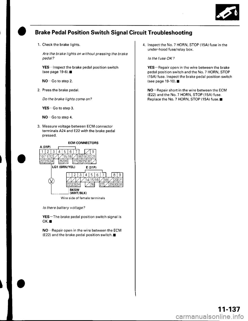
3. Measure voltage between ECM connector
terminals A24 and E22 with the brake pedal
presseo.
ls there battery voltage?
YES-The brake pedal position switch signal is
oK,I
NO Repair open in the wire between the Eclvl(E22) and the brake pedal position switch.l
Wire side of lemale terminals
4. Inspect the No. 7 HORN, STOP (15A) fuse ln the
under-hood fuse/relay box.
ls the tuse OK?
YES- Repair open in the wire between the brake
pedal position switch and the No.7 HORN, STOP( l5A) fuse, Inspect the brake pedal position switch(see page 19-10).1
NO Repair short in the wire between the ECM(E22) and the No.7 HORN, STOP (15A)fuse.
Replace the No.7 HORN, STOP (15A)fuse.t
11-137
Page 345 of 1139
ldle Control System
ldle Speed lnspection
NOTE:' Leave the idle air control (lAC) valve connecled.. Before checking the idle speed, check these items:- The malfunction indicator lamp (MlL) has not been
reported on.- lgnition timing- Spark plugs- Air cleaner- PCV system. Pullthe parking brake lever up. Start the engine, and
make sure the headlights are off.
1. Disconnect the evaporative emission (EVAP)
canister purge valve 2P connector.
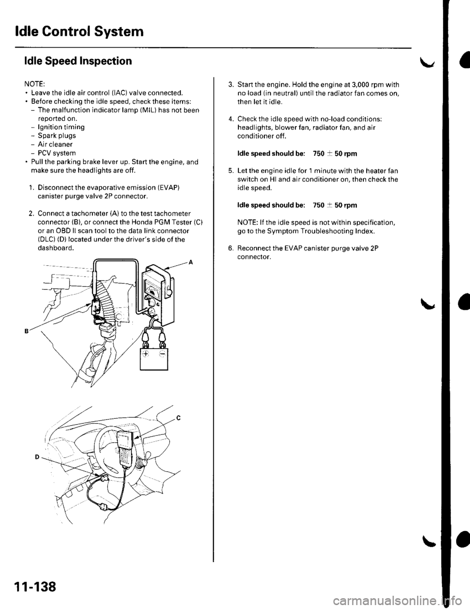
2. Connect a tachometer (A)to the test tachometer
connector (B), or connect the Honda PGM Tester (C)
or an OBD ll scan tool to the data link connector(DLC) (D) located under the driver's side of the
dashboard.
11-138
4.
3.
5.
6.
Start the engine. Hold the engine at 3,000 rpm with
no load (in neutral) until the radiator fan comes on,
then let it idle.
Check the idle speed with no-load conditions;
headlights, blower fan, radiator fan, and air
conditioner off.
ldle speed should be: 750 t 50 rpm
Let the engine idle for 1 minute with the heater fan
switch on Hl and air conditioner on, then check the
idle speed.
ldle speed should be: 750 t 50 rpm
NOTE: lf the idle speed is not wilhin specification,
go to the Symptom Troubleshooting Index,
Reconnect the EVAP canister purge valve 2P
connector.
Page 346 of 1139
ECM ldle Learn Procedure
The idle learn procedure must be done so the ECM can
learn the engine idle characteristics.
Do the idle learn procedure whenever you do any of
these actions:. Disconnect the battery.
Replace the ECM or disconnect its connector.
Reset the ECM.
NOTE: Erasing DTCS with the Honda PGM Tester
does not require you to do the idle learn procedure.
Remove the No.6 ECU {ECM) ( 15A) fuse from the
under-hood fuse/relay box.
Remove the No.19 baftery (80A) fuse from the under-
hood fuse/relay box.
Remove PGM-FI main relay 1.
Remove any of the wires from the under-hood fuse/
retay Dox.
Disconnect any of the connectors from the under
hood fuse/relay box.
Disconnect the connector between the engine
compartment wire harness and ECM wire harness.
Disconnect the G2 terminal from the transmission
ho u srng.
Disconnectthe G'l terminal from the body.
Disconnectthe G101 terminal from the cylinder head
cover.
Procedure:
To complete the idle learn procedure, do this:
1. Make sure all electrical items (Ay'C, audio, rear
defogger, l:ghts, etc.,) are off.
2. Start the engine, and hold it at 3,000 rpm with no
load {in neutral) until the radiator fan comes on, or
until the engine coolanttemperature reaches 194"F(90'c).
3. Let the engine idle for about 5 minutes with the
throttle fully closed.
NOTE: lf the radiator fan comes on, do not include its
running time in the 5 minutes.
11-139
Page 347 of 1139
Fuel Supply System
{
a
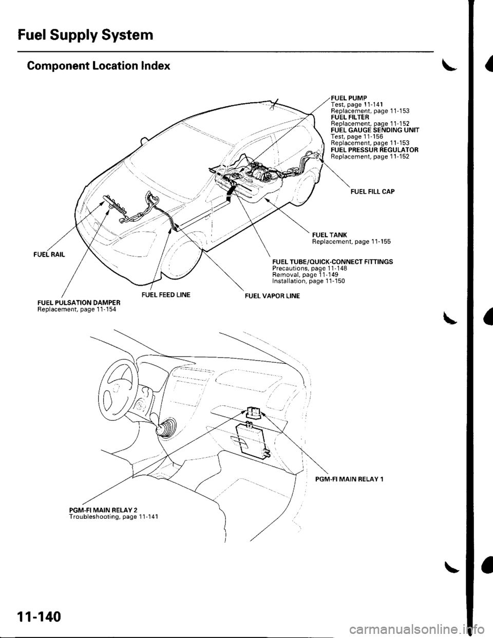
Component Location Index
FUEL FEED LINEFUEL PULSATION DAMPERReplacement, page 1 1'154
PGM.FI MAIN RELAY 2Troubleshooting, page'l'l-141
FUEL TUBE/OUICK.CONNECT FITTINGSPrecautions, page 1 1-148Removal, page 11-'149Installation, page 1 1-'l50
FUEL VAPOR LINE
i../
PUMPTest, page 11-141
FUEL FILL CAP
FUEL TANKReplacement, page'l 1-155
PGM.FI MAIN RELAY 1
Fleplacement, page 1 1'1 53FUEL FILTERReplacement, page 1 1-1 52FUEL GAUGE SENDING UNITTest, page 11-156Replacement, page 1 1-153FUEL PRESSUN REGULATORReplacement, page'1 1-'152
11-140
Page 348 of 1139
Fuel Pump Circuit Troubleshooting
lf you suspect a problem with the fuel pump, check that
the fuel pump actually runs; when it is on, you will hear
some noise if you listen to the fuel fill port with the fuel
fill cap removed. The fuel pump should run for 2
seconds when the ignition switch is first turned on. lf
the fuel pump does not make noise, check as follows:
1. Turn the ignition switch OFF.
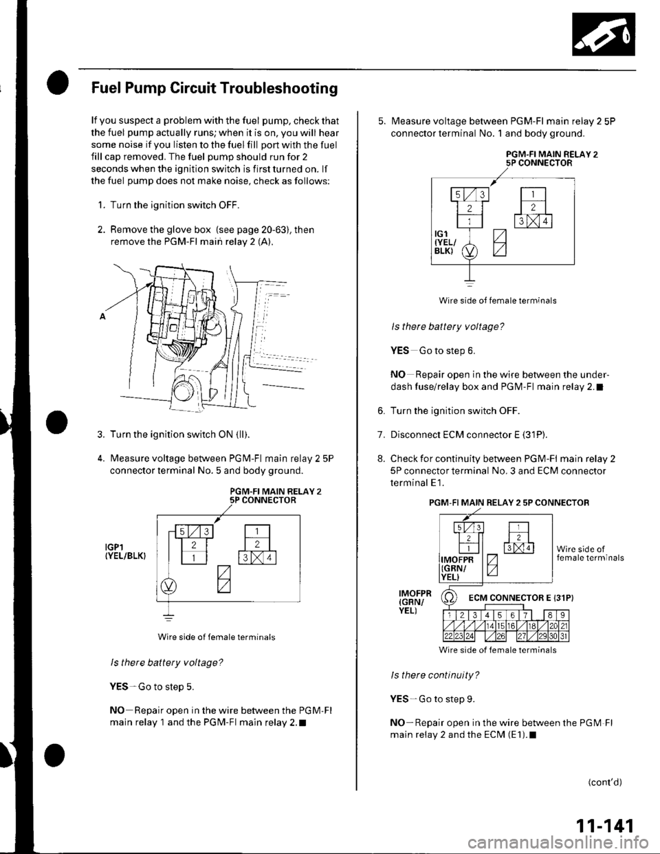
2. Remove the glove box {see page 20-63), then
remove the PGM-FI main relay 2 (A).
Turn the ignition switch ON {ll).
Measure voltage between PGM-Fl main relay 2 5P
connector lerminal No. 5 and body ground.
PGM.FI MAIN RELAY 25P CONNECTOR
IGPl(YEL/BLK}
Wire side of female terminals
ls there battery voltage?
YES-Go to step 5.
NO Repair open in the wire between the PGM'Fl
main relay 1 and the PGM-Fl main relay 2.t
3.
5. N4easure voltage between PGM-Fl main relay 2 5P
connector terminal No. 1 and body ground.
PGM.FI MAIN RELAY 25P CONNECTOR
Wire side oJ female terminals
ls there battery voltage?
YES Go to step 6.
NO Repair open in the wire between the under-
dash fuse/relay box and PGM-Fl main relay 2.1
6. Turn the ignition switch OFF.
7. Disconnect ECM connector E (31P).
8. Check for continuity between PGM-FI mainrelay2
5P connector terminal No. 3 and ECM connector
terminal E1.
PGM-FI MAIN RELAY 2 5P CONNECTOB
Wire side of female terminals
ls there continuity?
YES-Go to step 9.
NO-Repair open in the wire between the PGM Fl
main relay 2 and the ECM (E1).1
IMOFPR(GBN/YEL)
(cont'd)
11-141
Et2lFtxm
7-
z
ECM CONNECTOR E 131P}
Page 349 of 1139
![HONDA CIVIC 2003 7.G Workshop Manual FuelSupply System
(
(
L
10.
1�].
Fuel Pump Circuit Troubleshooting (contdl
Reinstallthe PGM-Fl main relay 2.
Turn the ignition switch ON (ll).
Measure voltage between ECI\4/PCM connector
terminal E1 HONDA CIVIC 2003 7.G Workshop Manual FuelSupply System
(
(
L
10.
1�].
Fuel Pump Circuit Troubleshooting (contdl
Reinstallthe PGM-Fl main relay 2.
Turn the ignition switch ON (ll).
Measure voltage between ECI\4/PCM connector
terminal E1](/img/13/5744/w960_5744-348.png)
FuelSupply System
(
(
L
10.
1'�].
Fuel Pump Circuit Troubleshooting (cont'dl
Reinstallthe PGM-Fl main relay 2.
Turn the ignition switch ON (ll).
Measure voltage between ECI\4/PCM connector
terminal E1 and body ground.
ECM CONNECTOB E {31P)
ls there battety voltage?
YES Go to step 12.
NO-Replace the PGM-Fl main relay 2.1
Turn the ignition switch OFF.
Reconnecl ECM connector E (31P).
Turn the ignition switch ON (ll), and measure
voltage between ECM connector terminal E1 and
body ground within the first 2 seconds after the
ignition switch was turned ON (ll).
ECM CONNECTOR E (31PI
13.
14.
Wire side of female terminals
Wire side of female terminals
11-142
t5.
to.
11.
18.
ls there battery voltage?
YES U pdate the ECM if it does not have the latest
so{1ware, or substitute a known-good ECM. then
recheck (see page 1 1-6). lf the symptom/indication
goes away with a known-good ECM, replace the
original ECM.I
NO Go to step 15.
Turn the ignition switch OFF.
Remove the rear seat cushion (see page 20-80).
Remove the access panel from the floor.
Measure voltage between fuel pump 5P connector
terminal No. 5 and body ground within the first 2
seconds after the ignition switch was turned ON (ll).
FUEL PUMP 5P CONNECTOR
wire side oI female terminals
ls there battery voltage?
YES Go to step 24.
NO-Go to step 19.
Turn the ignition switch OFF.
Remove the PGM-Fl main relay 2.
19.
20.
Page 350 of 1139

21. Connect PGM-Fl main relay 2 5P connector
terminals No. 1 and No. 2 with a iumDer wire.
PGM.FI MAIN RELAY 25P CONNECTOR
FUELPUMP(YEL/GRN)JUMPERWIRE
22.
23.
Wire side of {emale terminals
Turn the ignition switch ON (ll).
Measure voltage between fuel pump 5P connector
terminal No. 5 and body ground.
FUEL PUMP 5P CONNECTOR
Wire side ol female terminals
ls there battery voltage?
YES Replacethe PGM-Fl main relay2.t
NO-Repair open in the wire between the PGM-Fl
main relay 2 and the fuel pump 5P connector.l
Turn the ignition switch OFF.24.
FNI E
tri dffircr fv{YEL/BLK)
A
25. Check for continuity between fuel pump 5P
connector terminal No. 4 and body ground.
FUEL PUMP 5P CONNECTOR
Wire side of female terminals
ls there continuity?
YES Replace the fuel pump.l
NO-Repair open in the wire between the fuel
pump 5P connector and G551.1
11-143