Control HONDA CIVIC 2003 7.G Owner's Guide
[x] Cancel search | Manufacturer: HONDA, Model Year: 2003, Model line: CIVIC, Model: HONDA CIVIC 2003 7.GPages: 1139, PDF Size: 28.19 MB
Page 110 of 1139
t
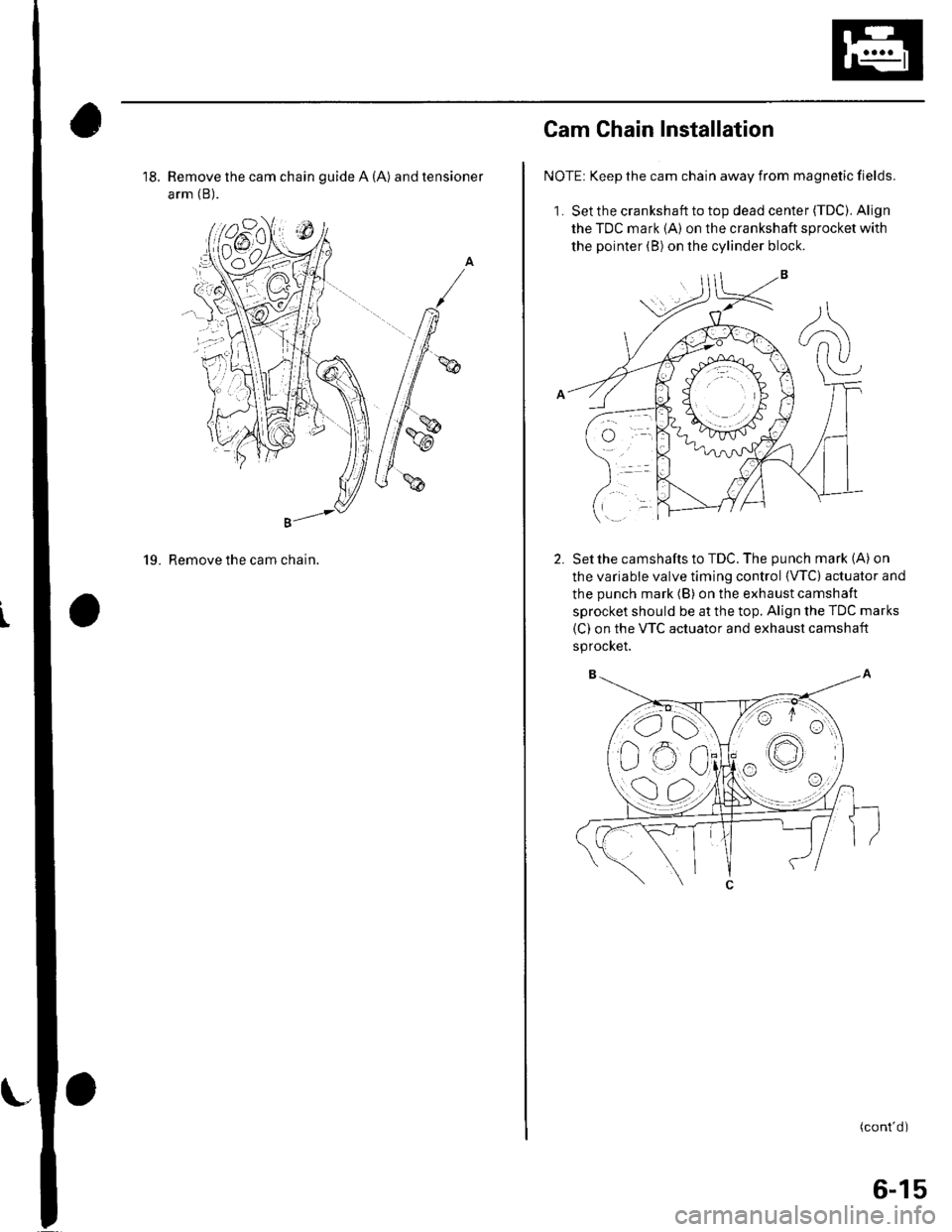
18. Remove the cam chain guide A (A) and tensioner
arm (B).
g"'-
19. Remove the cam chain.
,ot./6. | \{n$1J;
Cam Chain Installation
NOTE: Keep the cam chain away from magnetic fields.
1. Set the crankshaft to top dead center (TDC). Align
the TDC mark {A) on the crankshaft sprocket with
the pointer (B) on the cylinder block.
Setthe camshafts to TDC. The punch mark (A) on
the variable valve timing control {VTC) actuator and
the punch mark (B) on the exhaust camshaft
sprocket should be at the top. Align the TDC marks
(C) on the VTC actuator and exhaust camshaft
sprocKet.
(cont'd )
6-15
Page 114 of 1139
19.
20.
lnstall the variable valve timing control (VTC) oil
control solenoid valve (see step 1 on page 11'127).
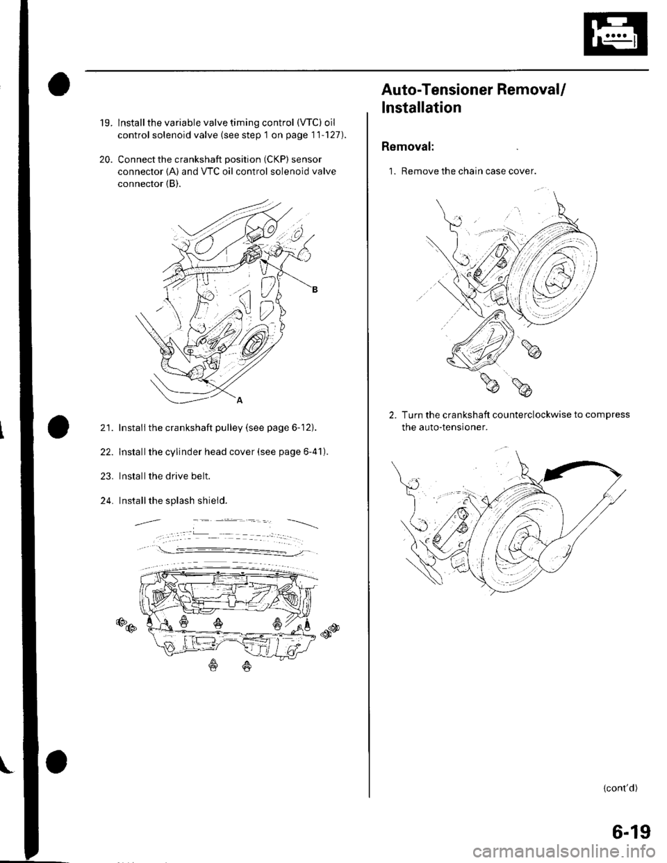
Connect the crankshaft position (CKP) sensor
connector {A) and VTC oil control solenoid valve
connector (B).
21. Install the crankshaft pulley (see page 6-12).
22. Installthe cylinder head cover (see page 6-41).
23. Installthe drive belt.
24. Installthe splash shield.
€D@
Auto-Tensioner RemovaU
lnstallation
Removal:
1. Remove the chain case cover.
Turn the crankshaft counterclockwise to compress
the auto-tensroner.
{cont'd)
6-19
Page 119 of 1139
Cylinder Head
tJ.
Cylinder Head Removal (cont'd)
Remove the rocker arm assembly (see page 6-26).
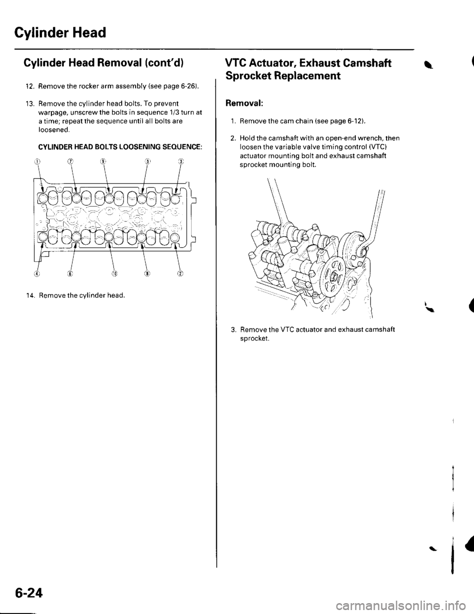
Remove the cylinder head bolts. To prevent
warpage, unscrew the bolts in sequence 1/3 turn at
a time; repeat the sequence until all bolts are
loosened.
CYLINDER HEAD BOLTS LOOSENING SEQUENGE:
14. Remove the cylinder head.
6-24
VTC Actuator, Exhaust Camshaft\
Sprocket Replacement
Removal:
1. Remove the cam chain (see page 6-12).
2. Hold the camshaft with an open-end wrench, then
loosen the variable valve timing control (VTC)
actuator mounting bolt and exhaust camshaft
sprocket mounting bolt.
Remove the VTC actuator and exhaust camshaft
sprocket.
I\(
I
Page 133 of 1139
Cylinder Head
Rocker Arm Assembly Installation
:,ean and dry the No. 5 rocker shaft holder mating
surfaces.
eeassemble the rocker arm assembly (see page 6-
21 t.
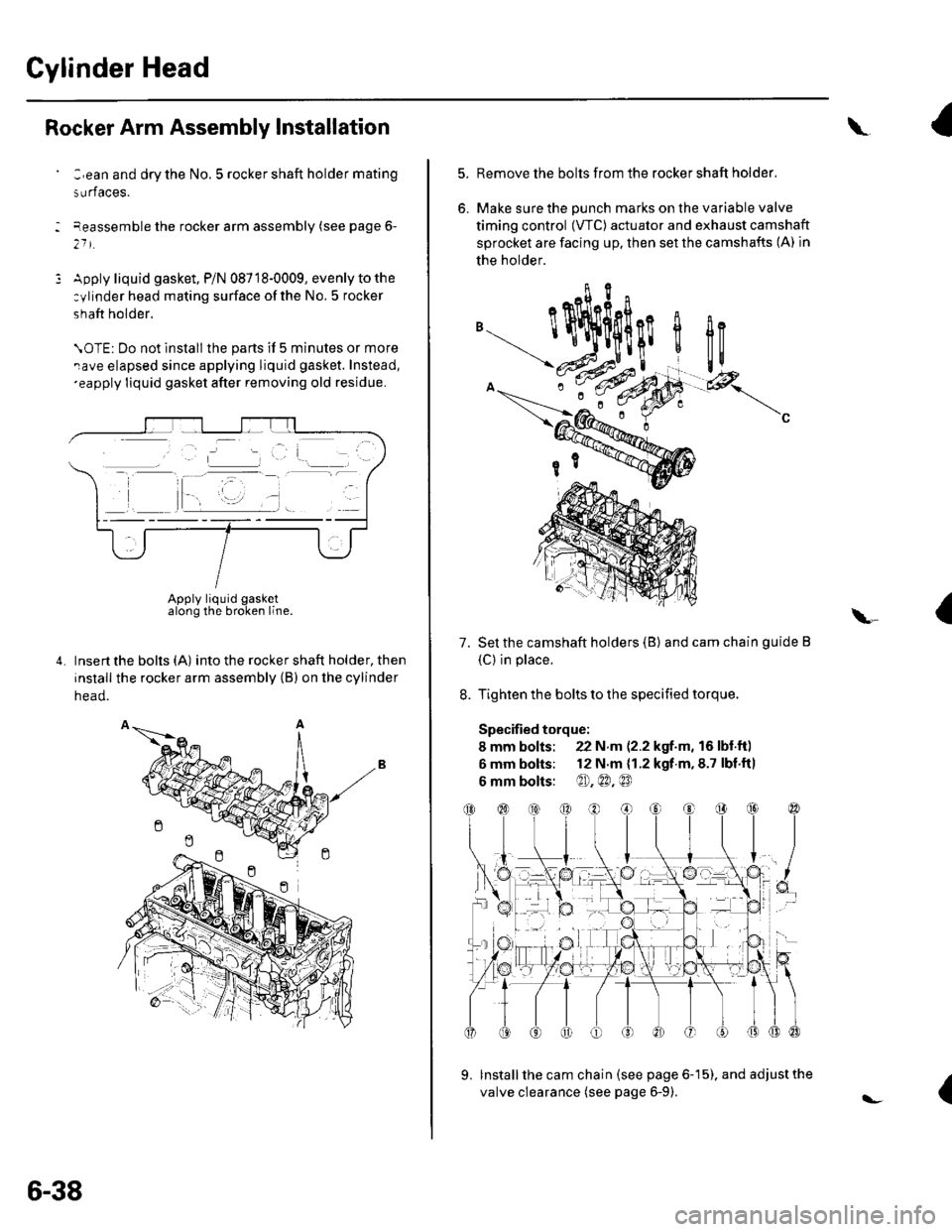
Apply liquid gasket, P/N 08718-0009, evenly to the
:ylinder head mating surface ofthe No. 5 rocker
shaft holder.
\OTE: Do not lnstall the parts if 5 minutes or more
rave elapsed since applying liquid gasket. Instead,'eapply liquid gasket after removing old residue.
Insert the bolts (A) into the rocker shaft holder, then
install the rocker arm assembly (B) on the cylinder
head.
Apply liquid gasketalong the broken line.
6-38
l-
\
5.
6.
Remove the bolts from the rocker shaft holder.
Make sure the DUnch marks on the variable valve
timing control (VTC) actuator and exhaust camshaft
sprocket are facing up. then set the camshafts (A) in
the holder.
Set the camshaft holders (B) and cam chain guide B
(C) in place.
Tighten the bolts to the specified torque.
Specified torque:
8 mm bolts: 22 N.m (2.2 kgf.m, 16 lbl.ft)
6 mm bolts: 12 N.m {1.2 kgf.m,8.7 lbf.fil
6 mm bolts: @),@.@
lnstall the cam chain (see page 6-15). and adjust the
valve clearance (see page 6-9).
I
flc
a\-
7.
{
Page 169 of 1139
![HONDA CIVIC 2003 7.G Owners Guide Component Location Index
OIL PUMPCHAIN TENSIONER
DRAIN BOLT
OIL PANRemoval, page 7 11Installataon, page 7-27
OIL PUMPOverhaLrl, page 8-8
HL]
BAFFLE PLATE
OIL FILTER FEED PIPEReplacement, page 8-7
OIL HONDA CIVIC 2003 7.G Owners Guide Component Location Index
OIL PUMPCHAIN TENSIONER
DRAIN BOLT
OIL PANRemoval, page 7 11Installataon, page 7-27
OIL PUMPOverhaLrl, page 8-8
HL]
BAFFLE PLATE
OIL FILTER FEED PIPEReplacement, page 8-7
OIL](/img/13/5744/w960_5744-168.png)
Component Location Index
OIL PUMPCHAIN TENSIONER
DRAIN BOLT
OIL PANRemoval, page 7 11Installataon, page 7-27
OIL PUMPOverhaLrl, page 8-8
HL]
BAFFLE PLATE
OIL FILTER FEED PIPEReplacement, page 8-7
OIL FILTERReplacement, page 8-6
OIL CONTROLORIFICE
WASHER
OIL PRESSURE SWITCHSwitch Test, page 8 4Oil Pressure test, page 8'4Replacement, page 8 16
-&\JrI
--t N\ksrarr lN-?cKEr dczt$)
#1
\OIL PUMPCHAIN GUIDE
8-3
Page 185 of 1139
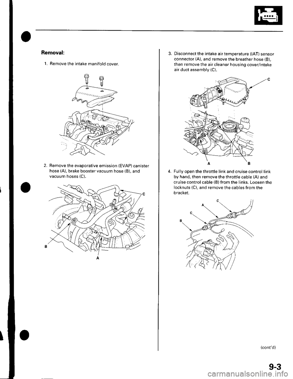
Removal:
'1. Remove the intake manifold cover.
2.Remove the evaporative emission (EVAP) canister
hose (A), brake booster vacuum hose (B), and
vacuum hoses {C).
3. Disconnectthe intake airtemperature (lAT) sensor
connector (A), and remove the breather hose (B),
then remove the air cleaner housing cover/intake
air duct assembly (C).
4.Fully open the throttle link and cruise control link
by hand, then remove the throttle cable (A) and
cruise control cable (B) from the links. Loosen the
locknuts {C). and remove the cables from the
bracket.
(cont'd)
(
9-3
Page 186 of 1139
Intake Manifold and Exhaust System
Intake Manifold Removal and Installation (cont'dl
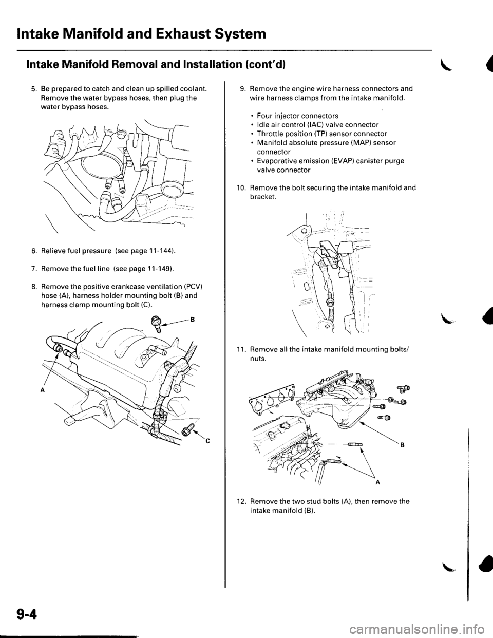
5. Be prepared to catch and clean up spilled coolant.
Remove the water bypass hoses, then plug the
water bypass hoses.
6. Relievefuel pressure (see page 11-'144).
7. Remove the fuel line (seepagell-149).
8. Remove the positive crankcase ventilation (PCV)
hose (A), harness holder mounting bolt (B) and
harness clamp mounting bolt (C).
9-4
\-
(
9.Remove the engine wire harness connectors and
wire harness clamps from the intake manifold.
. Four injector connectors. ldle air control (lAC) valve connector. Throttle position (TP) sensor connector. fvlanifold absolute pressure {lvlAP) sensor
connector. Evaporative emission (EVAP)canister purge
valve connector
Remove the bolt securing the intake manifold and
bracket.
'1 0.
11.Remove allthe intake manifold mounting bolts/
nuts.
Remove the two stud bolts (A), then remove the
intake manifold (B).
1'>
Page 187 of 1139
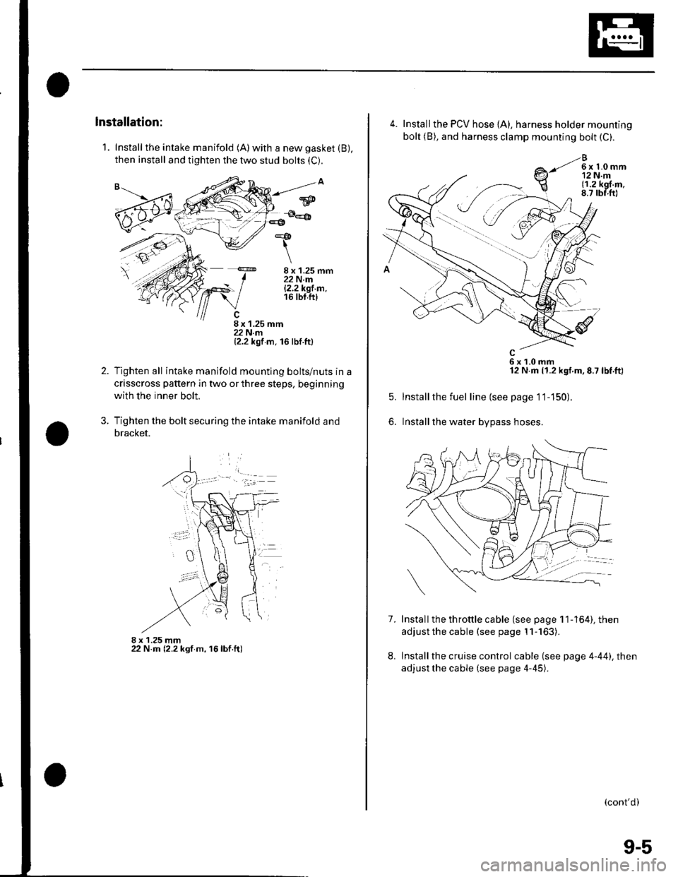
1. Install the intake manifold (A)with a new gasket (B),
then install and tighten the two stud bolts (C).
8 x 1.25 mm22 N.m|.2.2k91.m.16 tbt.ft)
8 x 1.25 mm22 N.rn(2.2 kgf m. 16 lbf.ttl
Tighten all intake manifold mountlng bolts/nuts in a
crisscross pattern in two or three steps, beginning
with the inner bolt.
Tighten the bolt securing the intake manifold and
bracket.
8 x 1.25 mm22 N.m (2.2 ksf m, 16lbf.ft)
*&
\
2.
?
w
4.
7.
5.
6.
Install the PCV hose {A), harness holder mounting
bolt (B), and harness clamp mounting bolt (C).
e-li*h,r
6x1.0mm12 N.m (1.2 kgf.m,8.7 lbf.ft)
Installthe fuel line (see page 11-150).
Installthe water bypass hoses.
Install the th rottle cable (see page 1 1-164), then
adjust the cable (see page 11-163).
Install the cruise control cable (see page 4-44). then
adjust the cable (see page 4-45).
8.
(cont'd)
9-5
Page 191 of 1139
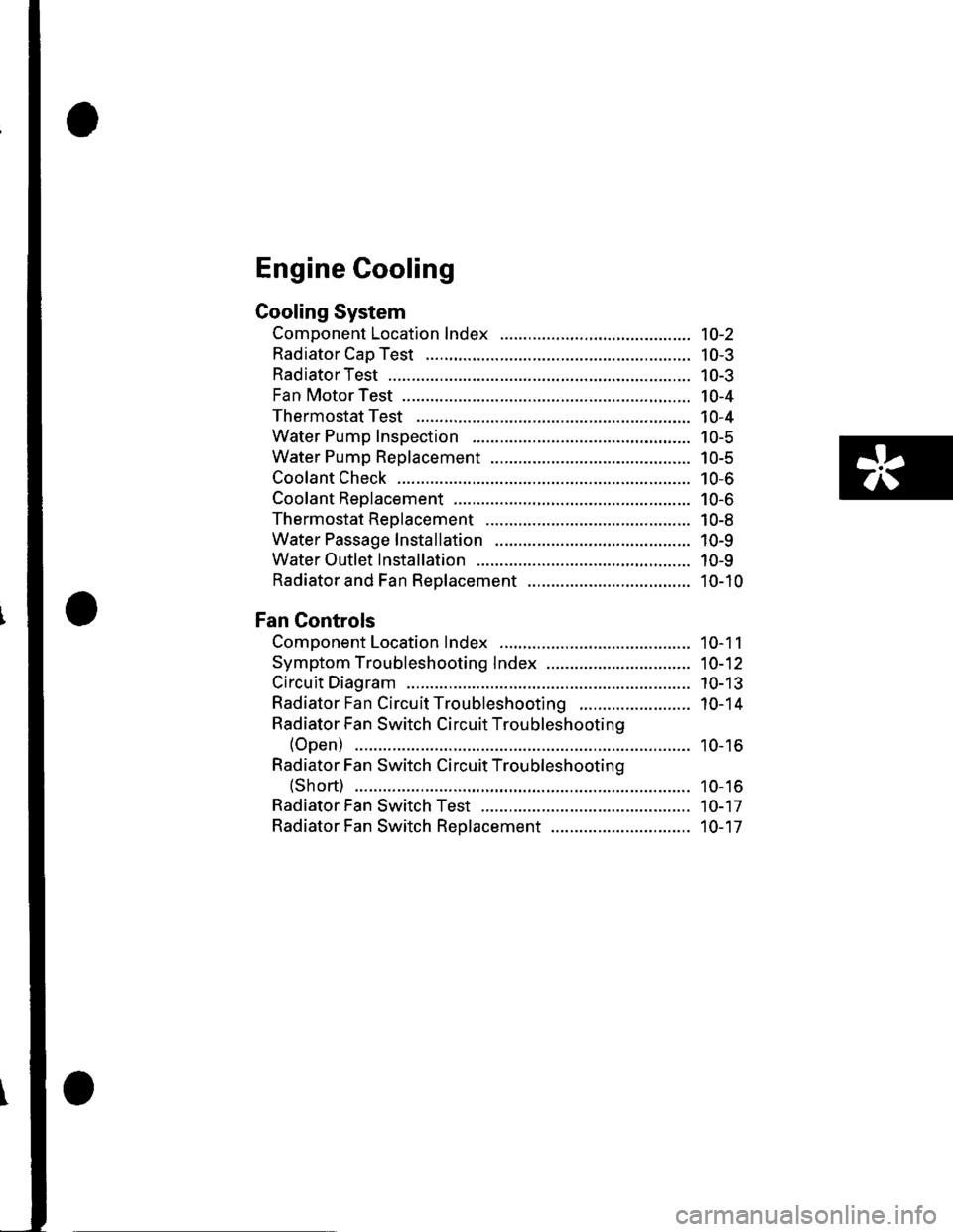
Engine Cooling
Cooling System
Component Location Index ......................................... 10-2
Radiator Cap Test ..................... .......... 10-3
RadiatorTest ............. 10-3
Fan Motor Test .......... l0-4
Thermostat Test ...................... ........... 10-4
Water Pump Inspection ..................... 10-5
Water Pump Replacement ................. 10-5
Coolant Check .............. ....................... 10-6
Coolant Replacement ......................... 10-6
Thermostat Replacement .................. 10-8
Water Passage Installation ................ 10-9
Water Outlet Installation .................... 10-9
Radiator and Fan Replacement ................................... 10-10
Fan Controls
Component Location Index ......................................... 10-11
Symptom Troubleshooting Index ............................... 10-12
Circuit Diagram ......... 10-13
Radiator Fan CircuitTroubleshooting ........................ 10-14
Radiator Fan Switch Circuit Troubleshooting
(Open) ............ ........ 10-16
Radiator Fan Switch Circuit Troubleshooting
(Short) ............ ........ 10-16
Radiator Fan Switch Test ................... 10-17
Radiator Fan Switch Reolacement .............................. 10-17
Page 196 of 1139
Cooling System
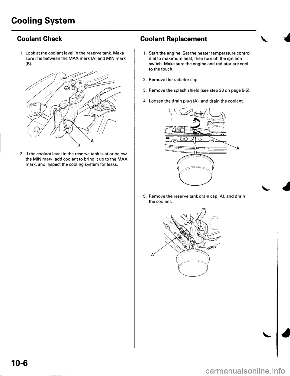
1 . Look at the coolant level in the reserve tank. Make
sure it is between the MAX mark (A) and MIN mark(B),
Goolant Check
lf the coolant level in the reserve tank is at or below
the MIN mark, add coolant to bring it up to the l\4AX
mark, and inspect the cooling system for leaks.
10-6
\-
Coolant Replacement
1.
\
Start the engine. Set the heater temperature control
dial to maximum heat. then turn off the ignition
switch. Make sure the engine and radiator are cool
to the touch.
Remove the radiator cap.
Remove the splash shield (see step 23 on page 5-5).
Loosen the drain plug (A), and drain the coolant.
Remove the reserve tank drain cap (A), and drain
the coolant.
\