Engine removal HONDA CIVIC 2003 7.G Owner's Guide
[x] Cancel search | Manufacturer: HONDA, Model Year: 2003, Model line: CIVIC, Model: HONDA CIVIC 2003 7.GPages: 1139, PDF Size: 28.19 MB
Page 543 of 1139
EPS Components
Steering Gearbox Removal (cont'd)
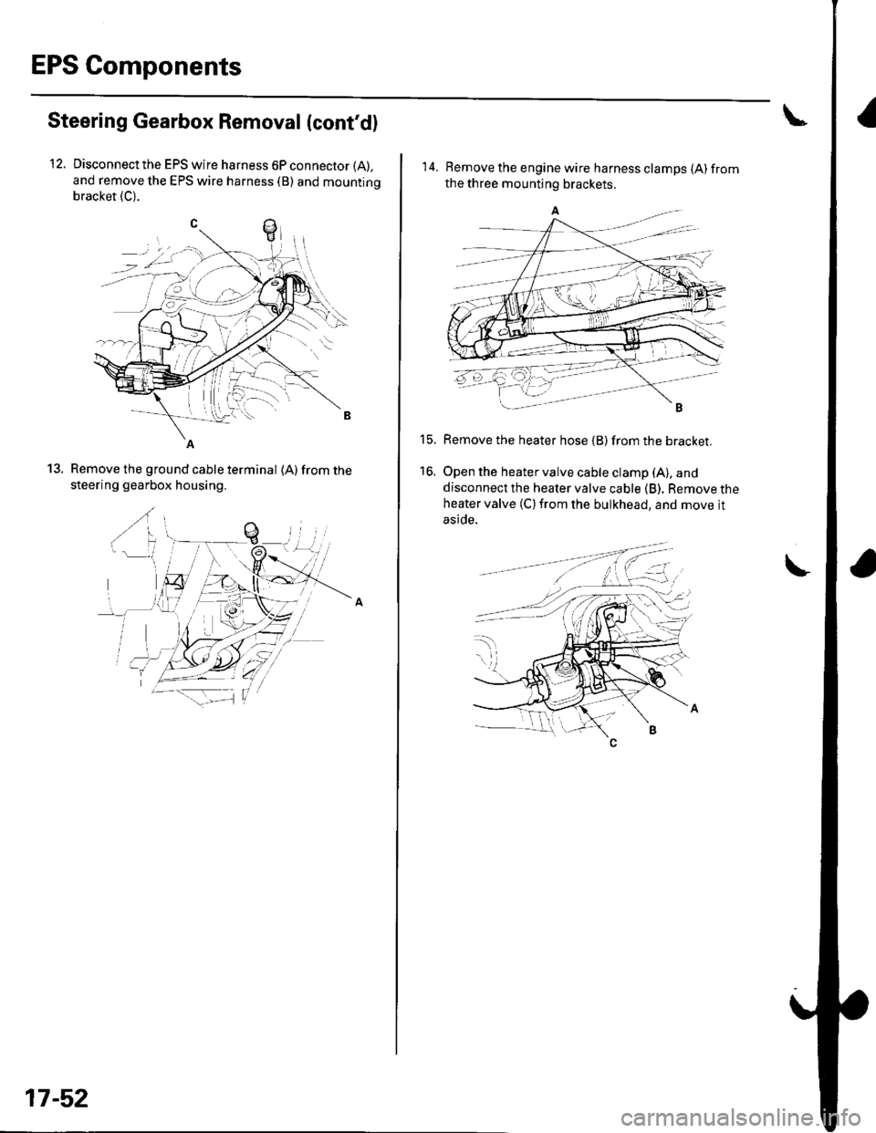
Disconnect the EPS wire harness 6P connector (A),
and remove the EPS wire harness (B) and mountino
bracket (C).
12.
Remove the ground cable terminal (A) from the
steering gearbox housing.
..(
.,/ a
b-H\
ry T,-.lt'^ \
'" \--
13.
_-1..1.-'
-a--zii F--_1
17-52
14. Remove the engine wire harness clamps {A)fromthe three mounting brackets.
Remove the heater hose {B) from the bracket.
Open the heater valve cable clamp (A), and
disconnect the heater valve cable (B). Remove theheater valve (C) from the bulkhead, and move jt
aside.
t5.
16.
I
Page 558 of 1139
EPS Control Unit Removal/
Installation
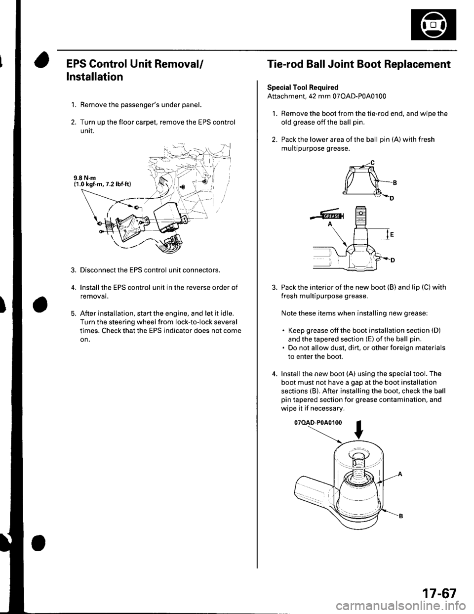
1. Remove the passenger's under panel.
2. Turn up the floor carpel, remove lhe EPS control
untr.
Disconnect the EPS control unit connectors.
lnstallthe EPS control unit in the reverse order of
removal.
After installation, start the engine, and let it idle.
Turn the steering wheelfrom lock-to-lock several
times. Check that the EPS indicator does not come
on.
3.
E
Tie-rod Ball Joint Boot Replacement
Special Tool Required
Attachment, 42 mm 07OAD-P0A0100
l. Remove the boot from the tie-rod end, and wipe the
old grease off the ball pin.
2. Pack the lower area of the ball pin(A)wilhfresh
mulr purpose grease.
3. Pack the interior of the new boot (B) and lip (C) with
fresh multipurpose grease.
Note these items when installing new grease;
. Keep grease offthe boot installation section (D)
and the tapered section (E) of the ball pin.
. Do not allow dust, dirt, or other foreign materials
to enter the boot.
4. Installthe new boot (A) using the specialtool. The
boot must not have a gap at the boot installation
sections (B). After installing the boot. check the ball
pin tapered section for grease contamination, and
wipe it if necessary.
07(lAD-P0A0100
*-4
r/ \-,d______i.l+_D
-6rA
17-67
Page 573 of 1139
18.
19.
Wash the knuckle and hub thoroughly in hlgh flash
point solvent before reassembly.
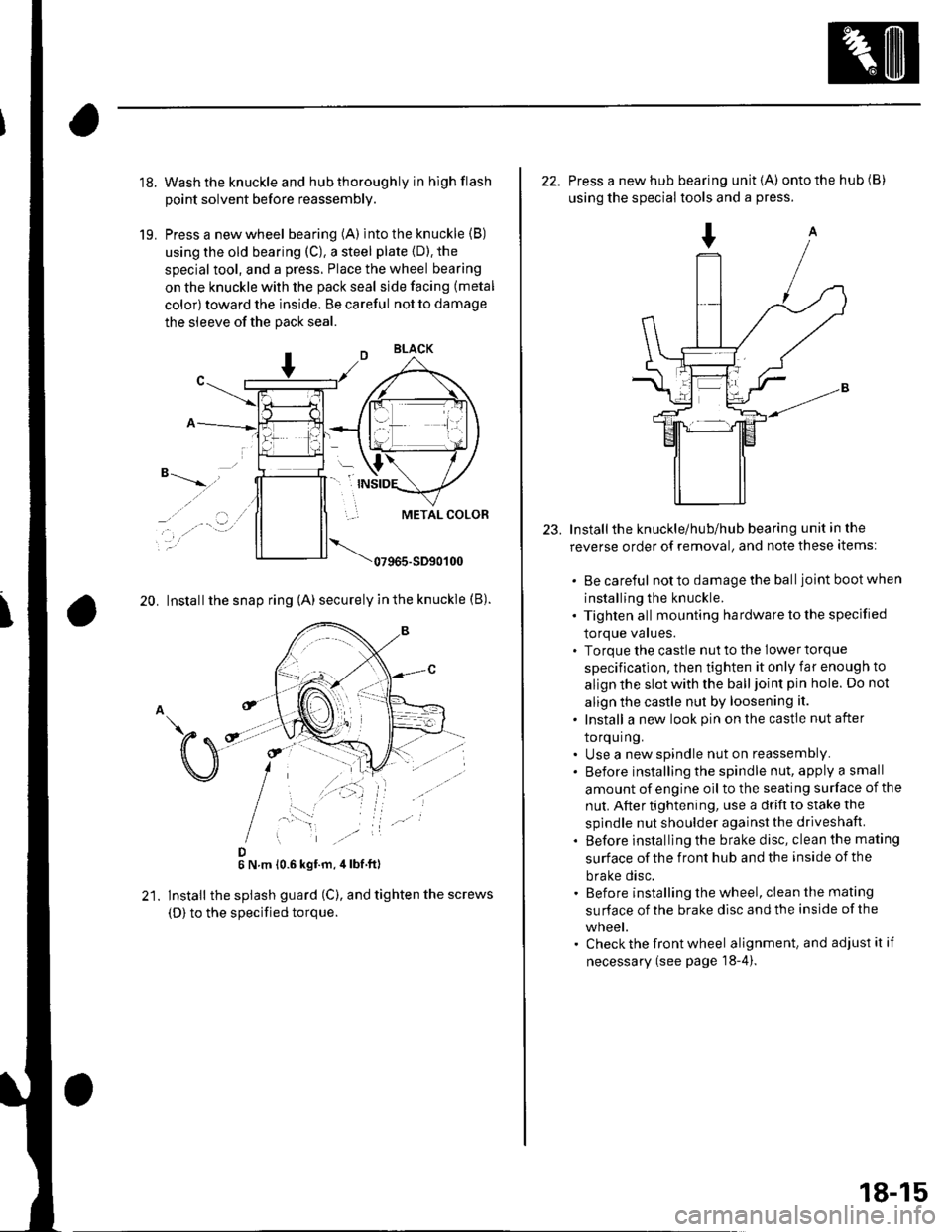
Press a new wheel bearing (A) into the knuckle (B)
using the old bearing (C), a steel plate {D). the
special tool, and a press. Place the wheel bearing
on the knuckle with the pack seal side facing (metal
color) toward the inside. Be careful not to damage
the sleeve of the pack seal.
"-t-_"*,,''
_, .' . . a-�.) ../
..-.
20. Install the snap ring (A) securely in the knuckle (B).
D6 N.m 10.6 kgf.m,4lbf ft)
lnstall the splash guard (C), and tighten the screws
(D) to the specified torque.
23.
22. Press a new hub bearing unit {A) ontothehub(B)
using the special tools and a press.
Installthe knuckle/hub/hub bearing unit in the
reverse order of removal, and note these items:
. Be careful notto damagethe balljoint bootwhen
installing the knuckle.. Tighten all mounting hardware to the specified
lOrque values.. Torque the castle nut to the lower torque
specification, then tighten it only far enough to
align the slot with the ball joint pin hole. Do not
align the castle nut by loosening it.
. Install a new look pin on the castle nut after
torquing.. Use a new spindle nut on reassembly.. Before installing the spindle nut, apply a small
amount of engine oil to the seating surface of the
nut. After tightening, use a drift to stake the
spindle nut shoulder against the driveshaft.
. Before installlng the brake disc, clean the mating
surface of the front hub and the inside of the
brake disc.. Before installing the wheel, clean the mating
su rface of the brake disc and the inside of the
wneet.. Check the front wheel alignment, and adjust it if
necessary (see page 18-4).
18-15
Page 587 of 1139
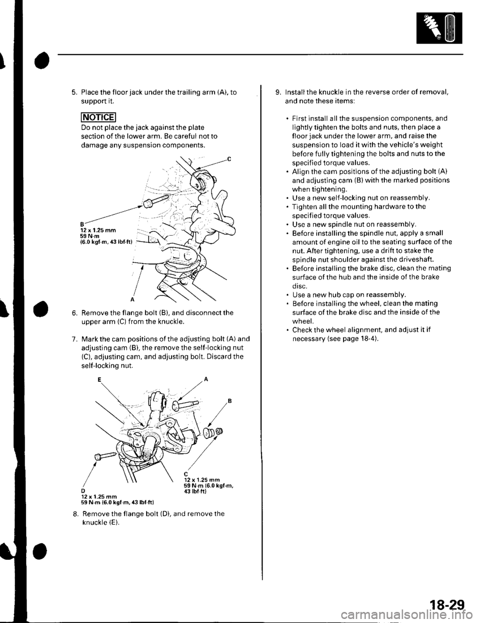
5. Place the floor jack under the trailing arm {A), to
support it.
Do not place the jack against the plate
section of the lower arm, Be careful not to
damage any suspension components.
12 x 1.25 mm59 N.m{6.0 ksf.m.43lbf.ft)
1.
Remove the flange bolt (B), and disconnect the
upper arm {C) from the knuckle.
Mark the cam positions of the adjusting bolt (A) and
adjusting cam (B), the remove the self-locking nut
{C}, adjusting cam, and adjusting bolt. Discard the
self-locking nut.
12 x 1.25 mm59Nm(6.0kgf.m,43 tbI.ftl12 x 1.25 mm59 N.m {6.0 kgf m,43lbl.ft)
8. Remove the flange bolt (D), and remove the
knuckle {E).
9. Installthe knuckle in the reverse order of removal,
and note these items:
. First install all the suspension components, and
lightly tighten the bolts and nuls, then place a
floor jack under the lower a rm, and raise the
suspension to load it with the vehicle's weight
before fully tightening the bolts and nuts to the
specified torque values.. Align the cam positions of the adjusting bolt (A)
and adjusting cam (B) with the marked positions
when tightening.. Use a new self-locking nut on reassembly.. Tighten allthe mounting hardware to the
specified torque values.. Use a new spindle nut on reassembly.. Before installing the spindle nut, apply a small
amount of engine oil to the seating surface of the
nut. After tightening, use a drift to stake the
spindle nut shoulder against the driveshaft.. Before installing the brake disc, clean the mating
surface of the hub and the inside of the brake
drsc.. Use a new hub cap on reassembly.. Before installing the wheel, clean the mating
surface of the brake disc and the inside of the
wheel.. Check the wheel alignment, and adjust it if
necessary {see page 18-4).
18-29
Page 610 of 1139
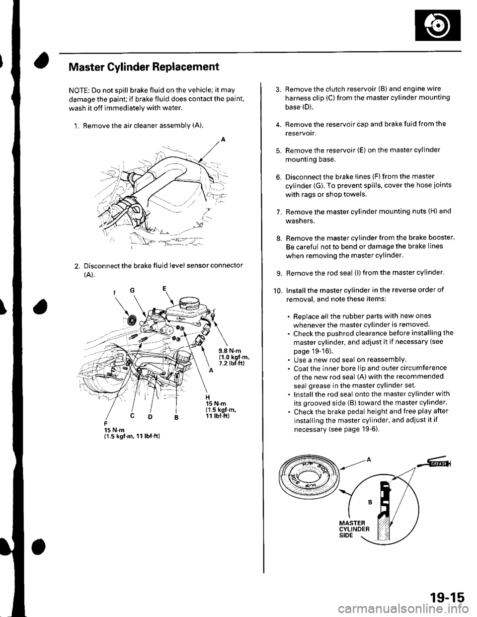
Master Cylinder Replacement
NOTE: Do not spill brake fluid on the vehicle; it may
damage the paint; if brake fluid does contact the paint,
wash it off immediately with water,
1, Remove the air cleaner assembly (A).
2, Disconnect the brake fluid level sensor connector
(A).
15 N.m{1.5 kgt.m, 11 lbt.ft)
3. Remove the clutch reservoir (B) andenginewire
harness clip (C)from the master cylinder mounting
base (D).
4. Remove the reservoir cap and brake fuid from the
reservoir.
5. Remove the reservoir (E) on the master cylinder
mountrng Dase.
6, Disconnect the brake lines (F)from the master
cylinder (G). To prevent spills, cover the hose joints
with rags or shop towels.
7. Remove the master cylinder mounting nuts {H) and
washers.
8. Remove the master cylinder from the brake booster.
Be careful not to bend or damage the brake lines
when removing the master cylinder.
9. Remove the rod seal (l) from the master cylinder.
10. Installthe master cylinder in the reverse order of
removal, and note these items:
. Replace all the rubber parts with new ones
whenever the master cylinder is removed.
. Check the pushrod clearance before installing the
master cylinder. and adjust it if necessary (see
page 19-16).. Use a new rod seal on reassemblY. Coat the inner bore lip and outer circumference
of the new rod seal {A) with the recommended
seal grease in the master cylinder set.
. Installthe rod seal ontothe master cylinder with
its grooved side (B)toward the master cylinder.
. Check the brake pedal height and free play after
installing the master cylinder, and adjust it if
necessary (see page 19-6).
19-15
Page 614 of 1139
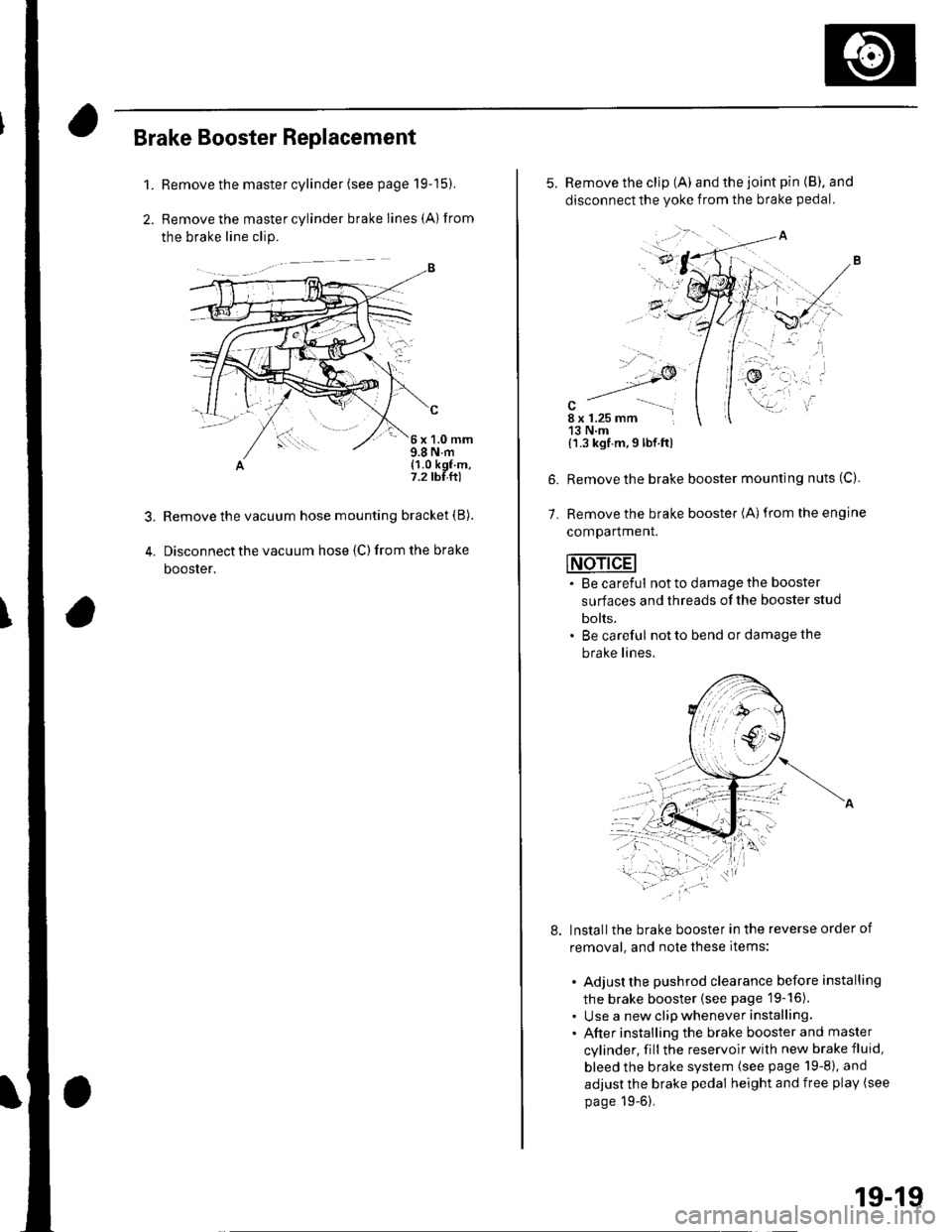
Brake Booster Replacement
1.Remove the master cylinder (see page 19-15).
Remove the master cylinder brake lines {A) from
the brake line clip.
c
6x1.0mm9.8 N.m(1.0 kgf.m,7.2 tbf.ft)
Remove the vacuum hose mounting bracket (B).
Disconnect the vacuum hose {C) from the brake
booster.
'-/
.,.,....
alu
i '..
5. Remove the clip (A) and the joint pin (B). and
disconnectthe yoke from the brake pedal.
7.
{'l.3 kgf.m,9 lbf.ftl
Remove the brake booster mounting nuts (C).
Remove the brake booster (A)from the engine
comparlmenr.
INdAdEI. Be careful not to damage the booster
surfaces and threads of the booster stud
bolts.. Be careful not to bend or damage the
brake lines.
lnstallthe brake booster in the reverse order of
removal, and note these items:
. Adjust the pushrod clearance before installing
the brake booster (see page 19-16).. Use a new clip whenever installing.. After installing the brake booster and master
cylinder, fill the reservoir with new brake fluid,
bleed the brake system (see page 19-8), and
adjust the brake pedal height and free play (see
page 19-6),
19-19
Page 652 of 1139
ABS Gomponents
ABS Modulator-Control Unit Removal and Installation {cont'dl
3. Disconnectthe six brake lines.
4. Remove the two I mm nuts.
5. Remove the ABS modulator-control unit (C).
Installation
'1. InstalltheABS modulatorcontrol unit, then tighten the two 8 mm nuts.
2. Align the connecting surface ofthe ABS control unit 3'lP connector.
3. PushinthelockoftheABScontrol unit 31P connector until you hear it click into place. then connect the connector.
4. Connect the six brake Iines.
5. Bleed the brake system, starting with the front wheels.
6. Connect the PGM Tester, and do the solenoid function test for each wheel.
7. Bleed the brake system again, staning with the front wheels.
8. Start the engine, and check that the ABS indicator and brake system indicator go off.
9. Disconnect the Honda PGM Tester. Test-drive the vehicle, and check that the ABS indicator and brake qvqtem
indicator do not come on.
19-58
Page 811 of 1139
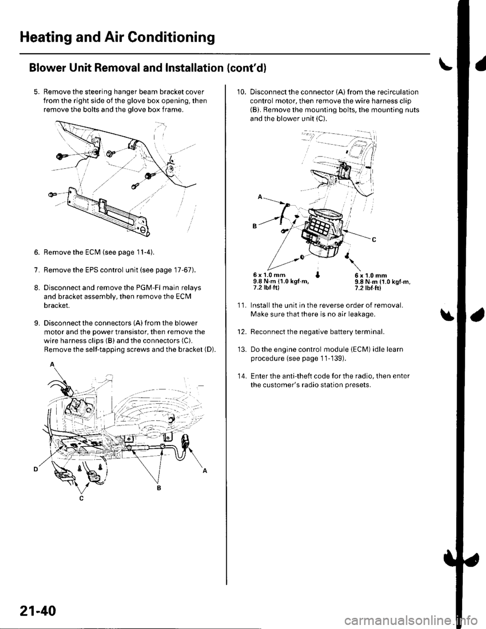
Heating and Air Gonditioning
Blower Unit Removal and Installation {cont'd}
Remove the steering hanger beam bracket cover
from the right side of the glove box opening, then
remove the bolts and the olove box frame.
1.
8.
9.
Remove the ECM (see page 11-4).
Remove the EPS control unit (see page 17-67).
Disconnect and remove the PGM-Fl main relays
and bracket assembly, then remove the ECM
bracket.
Disconnect the connectors {A) from the blower
motor and the power transistor, then remove the
wire harness clips (B) and the connectors (C).
Remove the self-tapping screws and the bracket (D).
A
21-40
10. Disconnectthe connector {A) from the recirculation
control motor, then remove the wire harness clip
{B). Remove the mounting bolts, the mounting nuts
and the blower unit (C).
6x 1.0 mm I9.8 N.m (1.0 kgt.m,7.2 tbt.ftl
6x1.0mm9.8 N.m (1.0 kgf.m,?.2 tbf.ft)
11.
14.
Installlhe unit in the reverse order of removal.
Make sure that there is no air leakage.
Reconnect the negative battery terminal.
Do the engine control module (ECM) idle learn
procedure {see page 11-139).
Enter the anti-theft code for the radio, then enter
the customer's radio station presets.
\
'13.
Page 816 of 1139
13. Installthe heater core and the evaporator core in
the reverse order of removal.
14. Installthe heater unit in the reverse order of
removal, and note these items:
. Do not interchange the inlet and outlet heater
hoses, and installthe hose clamps securely.. Refillthe cooling system with engine coolant (see
page 10-6).. Adjust the heater valve cable (see page 2'l-461.. Make sure that there is no coolant leakage.. Make sure that there is no air leakage.. Refer to evaporator core replacement {see step 6
on page 21-42).. Do the engine control module (ECl\4) idle learn
procedure (see page 11-139).. Enter the anti-theft code for the radio, then enter
the customer's radio station Dresets.
21-45
Page 818 of 1139
Compressor Replacement
1. lf the compressor is marginally operable, run the
engine at idle speed, and let the air conditioning
work for a few minutes, then shut the engine off.
2. Make sure you have the anti-theft code for the radio,
then write down the frequencies for the radio's
preset buttons.
3. Disconnect the negative cable from the battery.
4. Recover the refrigerant with a recovery/recycling/
charging station (see page 21-53).
5. Remove the alternator (see page 4-29).
6. Remove the Ay'C condenser fan assembly (see page
10-10).
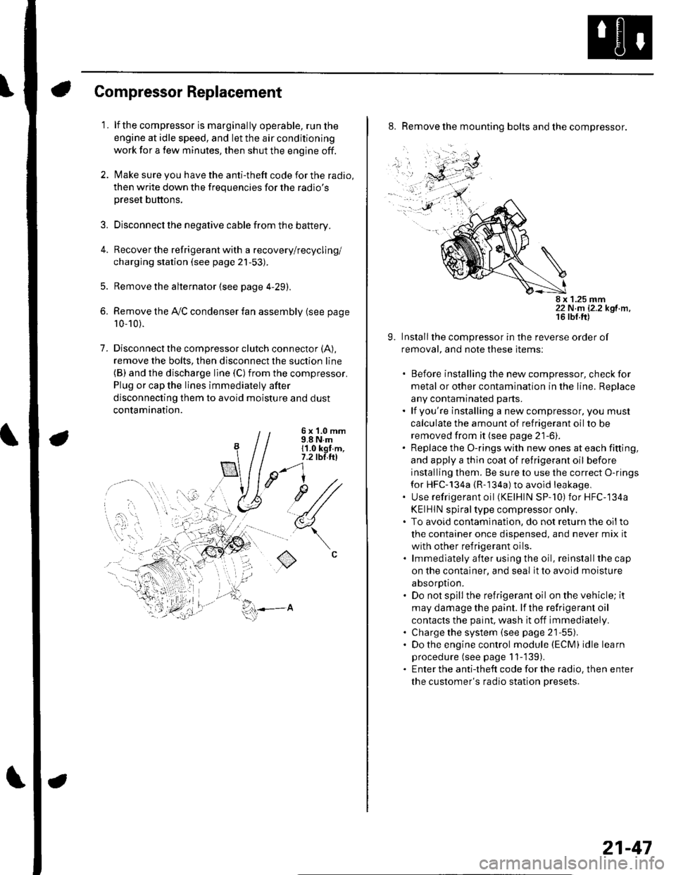
7. Disconnectthe compressor clutch connector (A),
remove the bolts, then disconnect the suction line(B) and the discharge line (C)from the compressor.
Plug or cap the lines immediately after
disconnecting them to avoid moisture and dust
contamination.
6 x '1.0 mm9.8 N.m11.0 kgt.m,7.2 tbl.ttl
u1/
(
o
8. Remove the mounting bolts and the compressor.
8 x 1.25 mm22 N.m 12.2 kgf.m.
9. Installthe compressor in the reverse order of
removal, and note these items:
. Before installing the new compressor, check for
metal or other contamination in the line. Replace
any contaminated parts.. lf you're installing a newcompressor, you must
calculate the amount of refrigerant oil to be
removed from it (see page 21-6).. Replace the O-rings with new ones at each fitting,
and apply a thin coat of refrigerant oil before
installing them. Be sure to use the correct O-rings
for HFC-134a {R-134a) to avoid leakage,. Use refrigerant oil (KElHlN SP-'10) for HFC-134a
KEIHIN spiral type compressor only.. To avoid contaminatlon, do not return the oilto
the container once dispensed, and never mix it
with other refrigerant oils.. lmmediately after using the oil, reinstallthe cap
on the container, and seal it to avoid moisture
absorption.. Do not spill the refrigerant oil on the vehicle; it
may damage the paint. lf the refrlgerant oil
contacts the paint, wash it off immediately.. Charge the system (see page 21-55).. Do the engine control module (ECM) idle learn
procedure (see page 11-'139).. Enter the antitheft code for the radio, then enter
the customer's radio station presets.
21-47