Engine removal HONDA CIVIC 2003 7.G Service Manual
[x] Cancel search | Manufacturer: HONDA, Model Year: 2003, Model line: CIVIC, Model: HONDA CIVIC 2003 7.GPages: 1139, PDF Size: 28.19 MB
Page 880 of 1139
Under-dash Fuse/Relay Box
Removal and Installation
SRS components are located in this area. Review the
SRS component locations {see page 23-13) andprecautions and procedures (see page 23-14) in the SRS
section before performing repairs or service.
Removal
1. Make sure you have the anti-theft code for the radio,
then write down the frequencies for the radio's
preset buttons.
2. Disconnectthe battery negative cable, then
disconnect the positive cable, and wait at least
three minutes.
3. Remove the driver's dashboard lower cover (see
page 20-59).
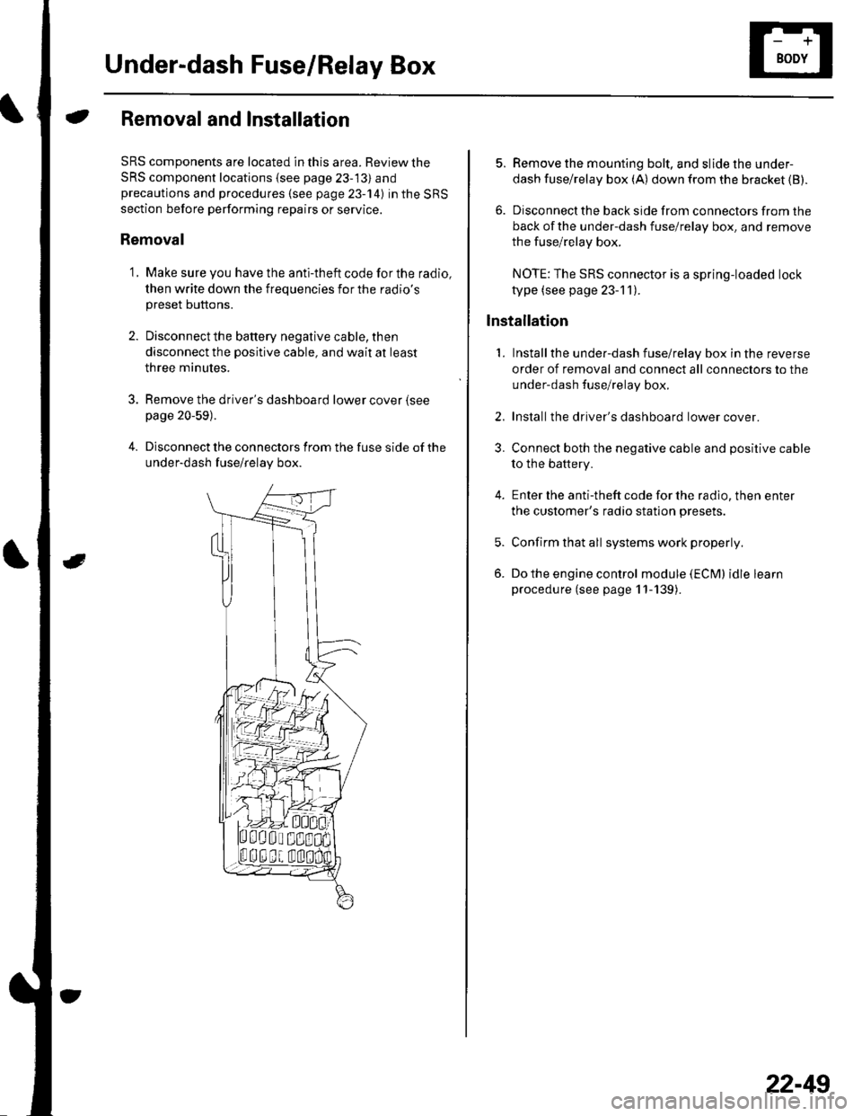
4. Disconnect the connectors from the fuse side of the
under-dash fuse/relay box.
5. Remove the mounting bolt, and slide the under-
dash fuse/relay box (A) down from the bracket {B).
6. Disconnect the back side from connectors from the
back of the under-dash fuse/relay box, and remove
the fuse/relay box.
NOTE:The SRS connector is a spring-loaded lock
type (see page 23-1 1).
lnstallation
1. Installthe under-dash fuse/relay box in the reverse
order of removal and connect all connectors to the
under-dash fuse/relay box.
2. Installthe driver's dashboard lower cover.
3. Connect both the negative cable and positive cable
to the battery.
4. Enter the anti-theft code for the radio, then enter
the customer's radio station presets.
5. Confirm that all systems work properly,
6. Do the engine control module (ECM) idle learn
procedure (see page 11-139).
22-49
Page 895 of 1139
Gauges
2.
3.
Gauge Assembly Replacement
1.Remove the instrument panel (see page 20-59),
then remove the upper column cover {see page 17-
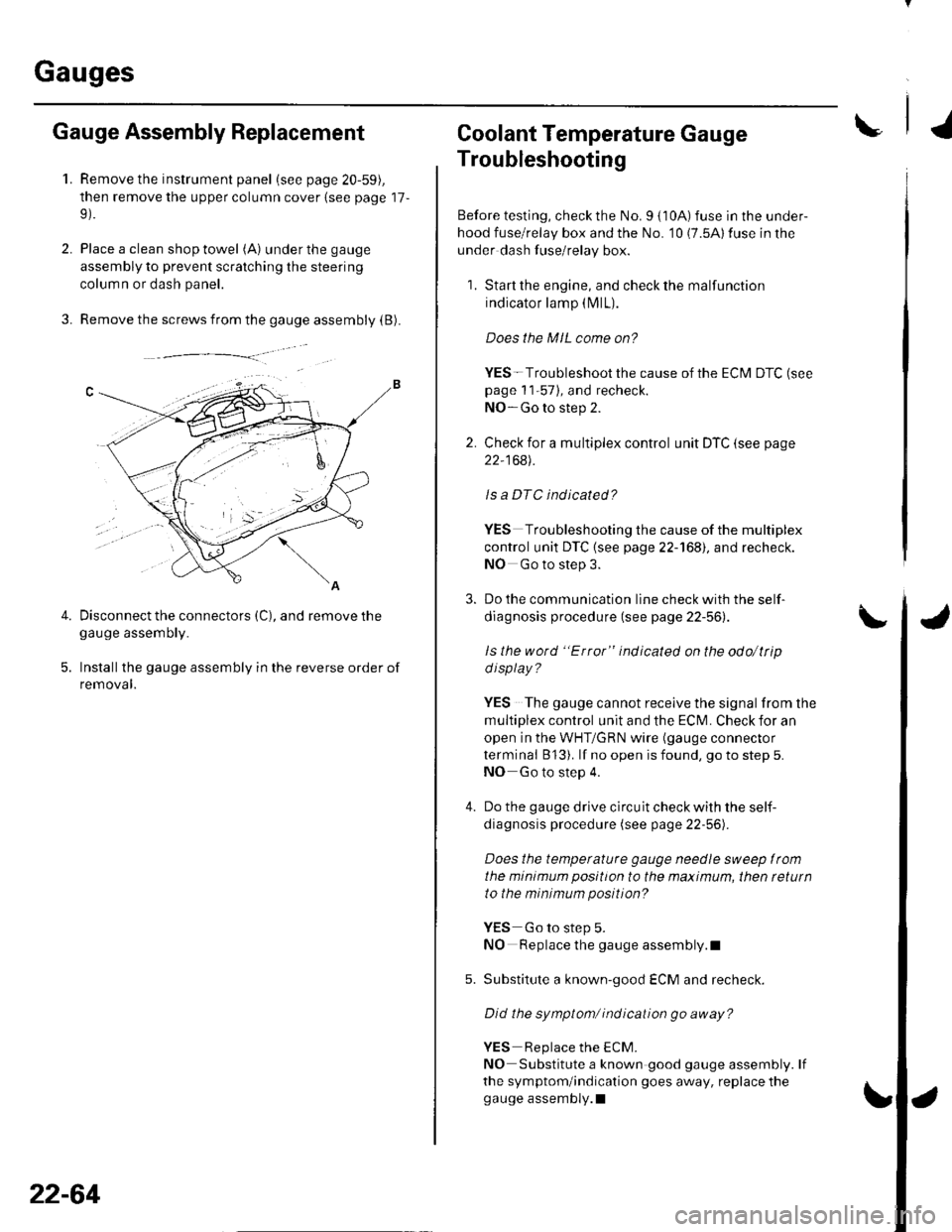
Place a clean shop towel (A) under the gauge
assembly to prevent scratching the steering
colum n or dash panel.
Remove the screws from the gauge assembly (B).
Disconnect the connectors (C), and remove thegauge assemDry.
Installthe gauge assembly in the reverse order of
removal.
Coolant Temperature Gauge
Troubleshooting
Before testing, check the No. I { 10A) fuse in the under-
hood fuse/relay box and the No. '10 (7.5A) fuse in the
under dash fuse/relay box.
1. Start the engine, and check the malfunction
indicator lamp (MlL).
Does the MIL come on?
YES- Troubleshoot the cause of the ECM DTC (see
page 1 1-57), and recheck.
NO-Go to step 2.
2. Check for a multiplex control unit DTC (see page
22,168).
ls a DTC ind icated?
YES Troubleshooting the cause of the multiplex
control unit DTC {see page 22-168), and recheck.
NO Go to step 3.
3. Do the communication line check with the self-
diagnosis procedure (see page 22-56).
ls the word "Error" indicated on the odo/ttip
d isplay ?
YES The gauge cannot receive the signal from the
multiplex control unit and the ECI\,4. Check for an
open in the WHT/GRN wire (gauge connector
terminal B 13). lf no open is found, go to step 5.
NO Go to step 4.
4. Do the gauge drive circuit check with the self-
diagnosis procedure (see page 22-56).
Does the temperature gauge needle sweep lrom
the minimum position to the maximum, then tetutn
to the minimum position?
YES Go to step 5.
NO Replace the gauge assembly.l
5. Substitute a known-good ECM and recheck.
Did the symptom/ ind ication go away?
YES Replace the ECM.
NO Substitute a known good gauge assembly. lf
the symptom/indication goes away, replace thegauge assembly.l
4.
22-64
Page 1132 of 1139
)
1.
Front lmpact Sensor Replacement
Removal
Disconnect the battery negative cable. and wait at
least 3 minutes before beginning work.
Disconnect the driver's airbag 4P connector lsee
step 2 on page 23-21), the front passenger's airbag
4P connector (see step 3 on page 23-21), both seat
belt tensioner 2P connectors (see step 5 on page
23-221, and both seat belt buckle 4P connectors (see
step 6 on page 23-22).
Remove the front inner fender (see pag e 2O-1O21.
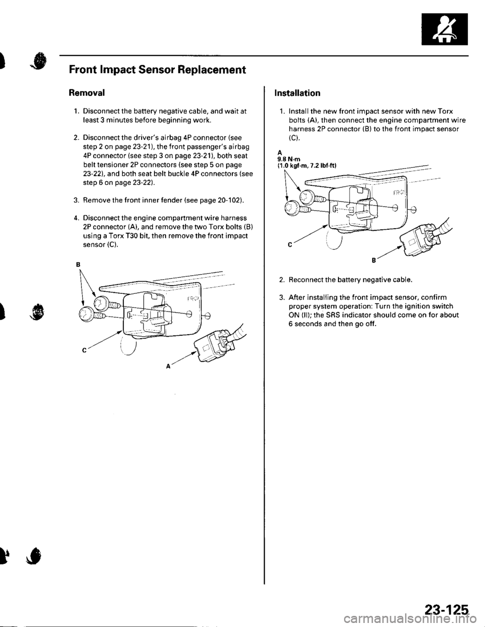
Disconnect the engine compartment wire harness
2P connector (A), and remove the two Torx bolts (B)
using a Torx T30 bit, then remove the front impact
sensor {C).
2.
)
)
Installation
1. Installthe new front impact sensor with new Torx
bolts (A), then connect the engine compartment wire
harness 2P connector (B) to the front impact sensor
{c).
A9.8 N.m
Reconnect the battery negative cable.
After installing the front impact sensor, confirm
proper system operation: Turn the ignition switch
ON (ll); the SRS indicator should come on for about
6 seconds and then go off.
(1.0 kgf.m,7.2lbf.ftl
23-125
Page 1135 of 1139
)
Orive BehInspecaron................ 4-26
Door PanelsRemoval/lnstallation -............................. 20-4
Door Sash TrimRep1acement......................................... 20 10
Door StrikersAdiustment ........................................... 20-13
Door Weatherst psBeplacement...........-............................. 20 1 1
EPS Conirol UnitRemoval/1nsta11ation ..................-......... 17-67
EPS Indicator CircuitTroubleshooting ................................... 17 -47
EPS MotorRemoval/lnstallation .-.......................... 17-49
EVAP CanisterRep1acement......................... ......... 11,189
EVAP Control Syst€mComponentLocation Index ..............'11-170
EVAP Two-Wey ValveTest ..........-.............-............................ 11 186
Evaporetor CoreRep1acement........................ . ... 21-42
Evaporator Tomperature SensorReplacement......................................... 21 -37Test..................................... ..........2137
EvaporrtoFHeater UnitReplacement........................................ 21 43
Exhaust ManifoldRemoval/1nsta11ation ................................ I 7
Exhaust Pipe8ep|acement............................................. 9-8
Front SpeakersRep|acement....................................... 22-102
Front SuspensionComponentLocation Index................... 18-3
Fueland EmissionsDescription ........................................... 11-12
Fuel Fill DoorAdjustment ..........-................................ 20 93
Fuel Fill Door OpenetBeplacement........................ . ............ 20.109
Fuel Fill Door Opener CableReplacement....................................... 20- lO7
Fuel FilterReplacement....................................... 1 1-152
Fuel Gauge Sending UnitTest ......................-.-..........-.................. 11'156
Fuel Injection Syslem (PGM"FIlComponent Location 1ndex................. 11-49
Fuel IniectorsRep1acemen1....................................... 1 1 1 1 l
Fuel Lines and HosesInspection .......................................... 1 1'146Removal ....................... . .. . .... 11-149Insta|1ation .......................................... 1 1 150
FuelPipe ProtectolReplacement....................................... 20-104
Fuel Pressure RegulatotReplacement....................................... 1 1-152
Fuel Pulsation DamperReplacemenl................................... 11 154
Fuel PumpReplacement,,,,,.,.,.,,,.,,,,,,,,,,,,.,.,.,,,..,.. 11-153
Fuel Pump CircuitTroubleshooting -.......-....................... 1 1-141
FuelSupply SystemComponent Location lndex .............. 11 140Adjustment................................... 11-144Test........-...-................. ... ............- 11-145
FuelTankBeplacemenl.............. . ..... .. 11 155
Fuel Tank Vapor ControlValveTest ......................-....... ... . . 11-187Replacement,,.,,...,.,,,.,.,,,,... .. .. 11 189
Fuses{See first page ofthis Index)
)
Rep|acement................. ..................... 4 26
Drive Belt Auto-tensionellnspection ............................................... 4 21Rep1acement.................................... ..4-28
Driver's PocketRemoval/lnstallation -........................... 20-60
Driver's TrayRemoval/lnstallation .........................-.- 20-65
DRL {Daytime Running LightslControl Unitlnput Test .................... ........ . . . ......22-16
DTCs(See first page olthis Index)
Dust and Pollen FillerReplacement......................................... 21-39
Dynamic Damper, DriveshaftsReplacement........................................... 16-8
ECT SensorReplacement.,.,,,.,.,,,,,,,,,,,,,,................ 1 1-1 14
El€ctrical Power Steering IEPS)Signal CircuitTroubleshooting ........ ... .. 11-135
EmblemsReplacement......................-................ 20-100
Engine AssemblyRemova1 .................................................... 5 2Installation ............._.................................. 5-9
Engine Block AssemblyComponent Location Inder ..................... 7.3
Engine Block, BareInspect|onRepair
Fan ControlsComponent Location Index................. 10'l 1Circuit Diagram .. ..... . .. . .................. 10 13
Fender Fairing, FrontReplacement...-................................... 20-103
Final Driven Gear. M/TReplacement.... . . ................................ 13-53
FrameRepair Chan............ ... ....................... 20 11 4
Frame StiffenelReplacement......-................................ 20- J'13
Front ConsoleRemoval/lnstallation ............................ 20 5lDisassembJy/Reassemb|y ................... 20 58
Front DoorsComponent Location Index................... 20-2Adiustment ........................................... 20.12
Front Driveshaft AssemblyInspeclion .................... ... ....16 3Remova1...................-...... ... .....16-3Disassembly ............................... .....165Resassemb|y ................................-......... 16-9Insta11arion ........................ ...... ............ l6 17
Front lmpact SensorsRep1acement............................ ...23 125
................7-15................1 11
)
Entry Light Control SystemComponent Location Index ...............-. 22-89Circuit Dia9ram .................................... 22 90
EPS ComponentsComponent Location 1ndex..........-...... 17-!7Description ........................ ...... ..17-24Circuit Diagram11 26(cont'd)
Page 1137 of 1139
)
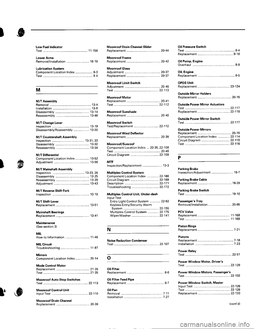
Low Fuel lndicatorTest.....................11-158Moonroof Drain Channel SliderReplacement......................................... 20'44
Moonroof FrameRep1acement,,,,,,,,,,.,.,.,.,.,.,.,,,,,,............ 20 42
MoonroolGlassAdiustment ........................................... 20-37Rep1acement......................................... 20 37
Moonroot Limit SwitchAdjustment ........................................-.- 20 46Test ...................................................... 22 113
Moonrool MotorReplacement....-.................................... 2D-41
Oil Pressure SwitchTest ................-.-........-................................ 8-4Replacement.........-................................. 8-16
Oil Pump, EngineOverhau1 ................................................... 8-8
Oil, EngineReplacement...-................-.-...................... 8-5
OPDS UnitReplacement....................................... 23- 124
Outside Mirror HoldersBeplacement......................................... 20-15
Outside Power Mirror ActuatorsTest ...................................................... 22-117Bepf acement..-.................................... 22-1 14
Outside Power Mirror SwitchTest ..-................................................... 22-111
Outsid€ Power MirrorsReplacement............................ ... .. . . . 20-15Component Location lndex .............. 22- 114Circuit Diagram .................................. 22-115Test -..................................................... 22-116
Lower ArmsRemoval/1nsta11ation............................ 18 19
Lubrication SystemComponent Location Index..................... 8-3Test............................................................ 8 4
M
M/TAssemblyRemoval.......... 13-4 Test...................... 22-1 12lnstallation............. 13-8
.........21,35
Disassembly ......................................... 13-14Resassembly .. ... ................. 13-46
M/TChange Leverlnspection ............................................. 13-19Disassembly 8eassemb1y ................... 13-20
M/T Countershaft AssemblyInspection ....................................... 13 31, 33Disassemb1y ......................................... 13-32Resassemb|y ........................................ 13-34
M/T DifferentialComponentLocation Index................. 13-52Adiuslment ........................................... 13-56
M/T Maifthaft Assembly1nspection ... ................................... 13-23, 26Disassembly ......................................... 13 25Resassembly ........................................ 13 28Adjustment ........................................... 13-43
M/T Reverse Shift ForkInspection .................... ........................ l3 19
M/T Shift LevelReplacement......................................... 13-51
Mainshaft BearingsReplacement....,.................................... 13 41
MairtenancelSee section 3)
MILHow to Informatron ............................. 1 1.46
MIL CircuitTroubleshooting .......... .- . . . . ......... 11 97
MirrorsComponentLocation Index................. 20'14
Mode Control MotorReplacement
Moonrool SunshadeRep1acement....................... . . ............. 20 40
Moonroof SwitchTesVRep1acement .............................. 22- l 12
Mooniool Wind Def lectorReplacement.......................-................. 20-38
Moonroof/SunroofComponent Location Index ... 20-35, 22-108Test ........................................................ 20-48Cf rcuit Diagram .................................. 22- 109
MTFInspection/Rep1acement. .......... ........... 13-3
Muhiplex Control SystemComponentLocation lndex ..............22 168Circuit Diagram .................................. 22-1690escription ......................................... 22-17 1Troubleshooting ................................ 22-17 2
Muliiplex Control Unit, Under-dashInput TestEntry Light Control Sysiem ............. 22-92Keyless Entry/Security AlarmSystern .-....................................... 22-155MultiplexControl System .............22 115Wiper/Washer................................. 22'1 41
NoiseTest,,Reduction Condenser
Parking ErakeInspection Adjustment ........... .............. 19-7
Parking Brake CableRep1acement......................................... 19-26
Parking Erake Switch
P
l
Test ...................... 19-10
Test............................... . ...........2135
Moonroof Auto Stop SwitchosTest ...................................................... 22'113
Moon.oot Control Unillnput Test ............................................ 22-110
Moonroof Drein ChannelBeplacement ... . ....... ......................... 20 39
Oil Filte]Replacement............................................. 8-6
Oil Filter Feed PipeReplacement............... . ..-,...,.,,,,,,,,8-7
Oil PanRemoval .............,.,,,,,,,,,,,,.,.,,,.........-....... 7 1 1lnstallation .............................................. 7 -27
Passenger's TraVRemoval/lnstallation ............................ 20-65
PCV ValveBeplacement....................................... 1 1'169Test........................................... l1 169
Piston Rings8ep1acement................................-.-...-.- 7-21
PistonsReplacement...................-....................... 7-181nsta|1ation ...................................... ...1-23
Power R€layTest ...............-.-...................................... 22-51
Power Window Motor, Driver'stesl.....,,,, .,.,,,............
Power Window Motors, Passenger's
Power Window Switch, Masterlnput Test ..........-.........-....................... 22-126Tesr ....... . ............................................ 22 124Replacement....................................... 22-133
N
..............22 101
o
l' ,e
(cont'd)