HONDA CIVIC 2003 7.G Workshop Manual
CIVIC 2003 7.G
HONDA
HONDA
https://www.carmanualsonline.info/img/13/5744/w960_5744-0.png
HONDA CIVIC 2003 7.G Workshop Manual
Trending: starter, OBD port, wiper fluid, headlight bulb, Power steering, power mirrors, rear view mirror
Page 761 of 1139
2.
5.
Fuel Fill Door Opener Cable Replacement
SRS components are located in this area. Review the SRS component locations (see page 23-13) and the precautions
and procedures (see page 23-14) in the SRS section before performing repairs or service.
NOTE;. Put on gloves to protect your hands.. Take care notto scratch the body and related parts.
1. Remove these items from the left side of the vehicle:
. Door silltrim {see page 20-50). Rear side trim panel (see page 20-51)
Pullthe carpet back as necessary (see page 20-55).
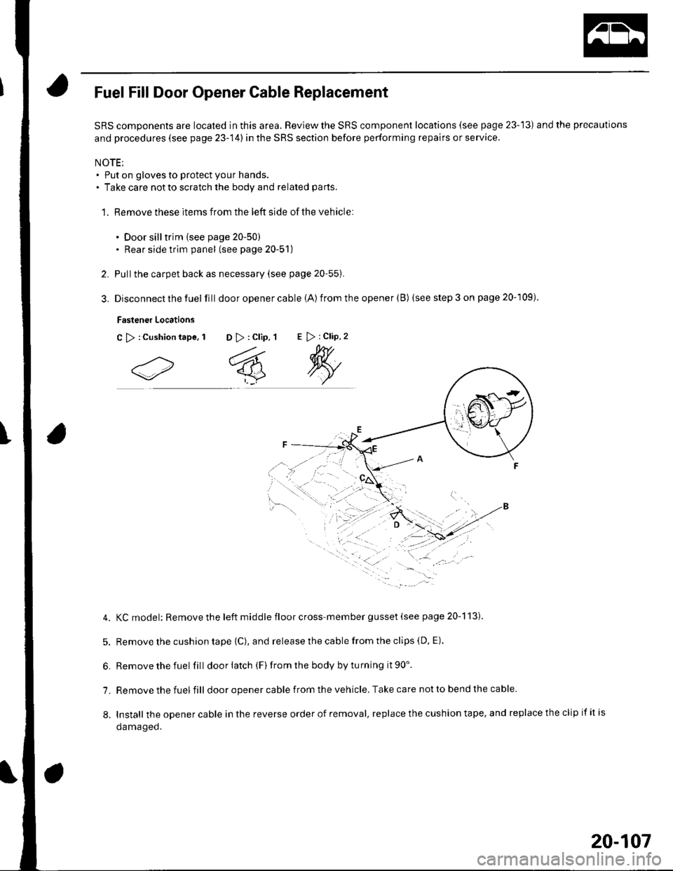
Disconnect the fuel fill door opener cable (A) from the opener (B) (see step 3 on page 20-109).
Fastener Locations
C >:Cushiontape, 1 D >: Clip, 1E > : Clip, 2
4. KCmodel: Removethe left middle floor cross-member gusset (see page 20-113).
5. Remove the cushion tape {C), and release the cable from the clips (D, E).
6. Removethefuel fill doorlatch (F)fromthe bodybyturning it90'.
7. Remove the fuel fill door opener cable from the vehicle. Take care not to bend the cable
8. Install theopenercableinthereverseorderofremoval,replacethecushiontape,andreplacetheclipifitis
oamageo.
20-107
Page 762 of 1139
Openers
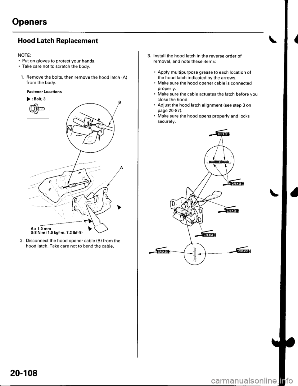
Hood Latch Replacement
NOTE:. Put on gloves to protect your hands.. Take care not to scratch the body.
1. Remove the bolts, then remove the hood latch (A)
from the body.
Fastener Locations
> i Bolt, 3
Disconnect the hood opener cable (B) from the
hood latch. Take care not to bend the cable.
--------------'6x1.0mm9.8 N.m (1.0 kgf.m, 7.2lbf.ft)
20-108
Installthe hood latch in the reverse order of
removal, and note these items:
. Apply multipurpose grease to each location of
the hood latch indicated by the arrows.. Make sure the hood opener cable is connected
properly.
. Make sure the cable actuates the latch before you
close the hood,. Adjustthe hood latch alignment (see step 3 onpage 20-87).. Make sure the hood opens properly and locks
securely.
Page 763 of 1139
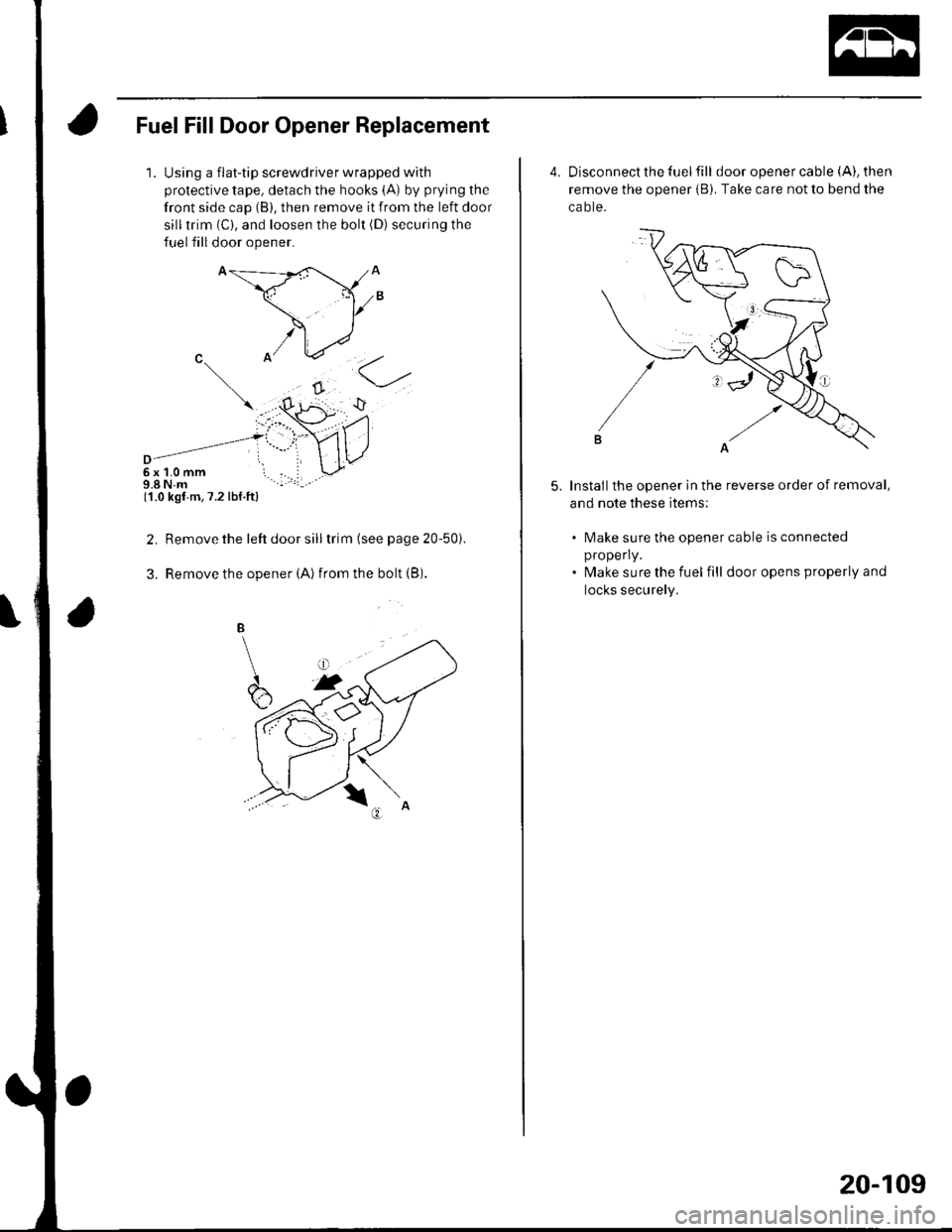
Fuel Fill Door Opener Replacement
1.Using a flat-tip screwdriver wrapped with
protective tape, detach the hooks (A) by prying the
front side cap (B), then remove it from the left door
silltrim (C), and loosen the bolt (D) securing the
fuel fill door opener.
6x1.0mm9.8 N.m11.0 kgf m,7.2 lbf.ft)
Remove the left door sill trim (see page 20-50i.
Remove the opener (Alfrom the bolt {B).
2.
3.
4. Disconnect the fuel fill door opener cable (A), then
remove the opener iB). Take care not to bend the
ca o te.
Installthe opener in the reverse order of removal,
and note these items:
5.
lMake sure the opener cable is connected
properly.
lvlake sure the fuel fill door opens properly and
locks securely.
20-109
Page 764 of 1139
Openers
Hatch Handle Replacement
NOTE: Put on gloves to protect your hands.
1. Remove these items:
. Hatch lower trim panel (see page 20-53). Rear license trim panel (see page 20-98)
2. Remove the rear window wiper motor (see page
22-1461.
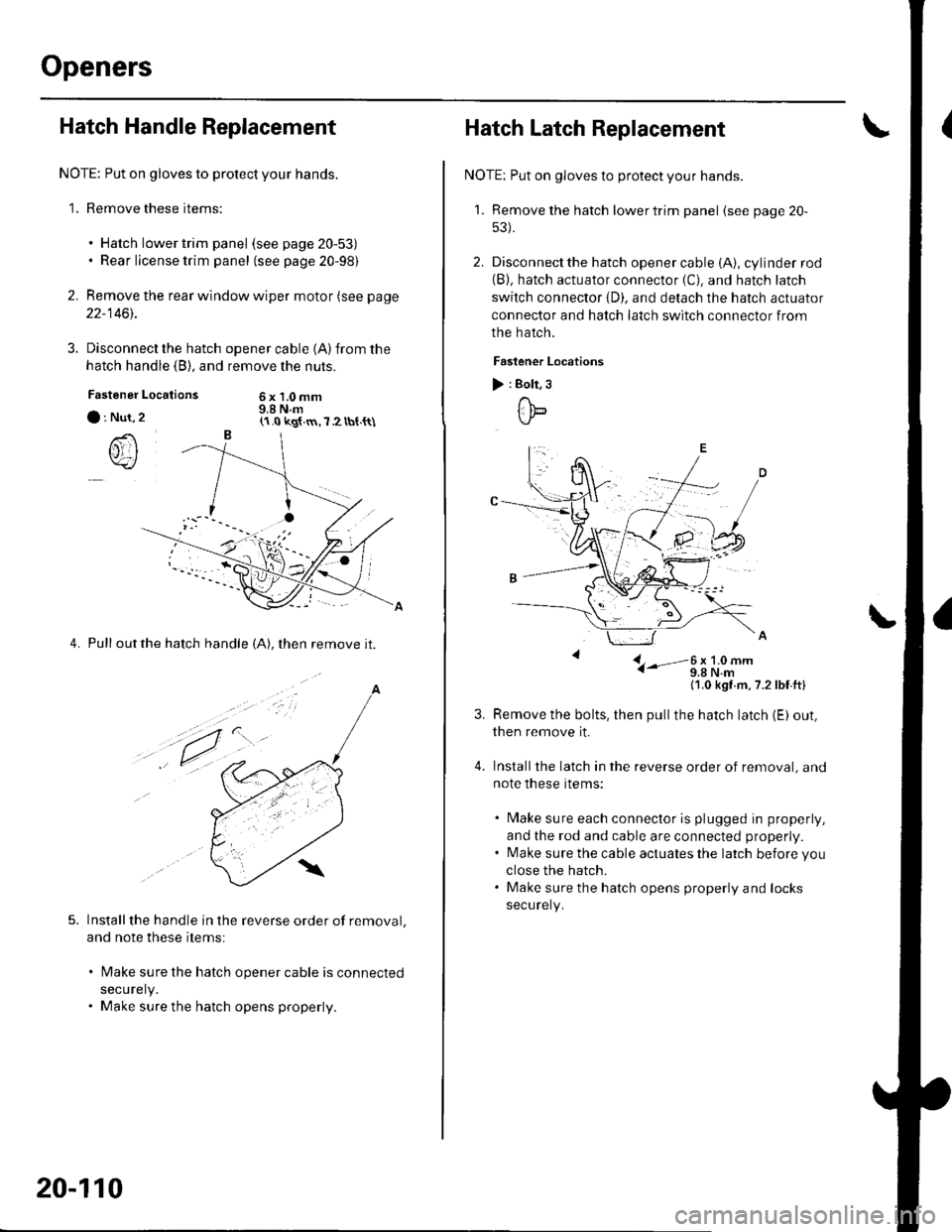
3. Disconnect the hatch
hatch handle (B), and
Locations
opener cable 1A)from the
remove the nuts.
6x1.0mm9.8 N.mFastener
a : Nut,
()rI
4. Pull outthe hatch handle (A), then remove it.
Installthe handle in the reverse order of removal.
and note these items:
lMake sure the hatch opener cable is connected
securely.
Make sure the hatch opens properly.
(1.0 kg{.m,7 2 tbt.{t\
a
,t.
20-110
Hatch Latch Replacement
NOTE: Put on gloves to protect your hands.
'1. Remove the hatch lowertrim panel (see page 20-
53).
2. Disconnect the hatch opener cable (A), cylinder rod(B). hatch actuator connector (C). and hatch latch
switch connector {D). and detach the hatch actuator
connector and hatch latch switch connector from
the hatch.
Faslener Locations
) : Bolt, 3
ttb
L- i-'-3;li9#-
11,0 kgt m,7.2lbf ftl
Remove the bolts, then pullthe hatch latch (E) out,
then remove it.
Installthe latch in the reverse order of removal, and
note these items:
. Make sure each connector is plugged in properly,
and the rod and cable are connected properly.. l\4ake sure the cable actuates the latch before you
close the hatch.. Make sure the hatch opens properly and locks
securely.
Page 765 of 1139
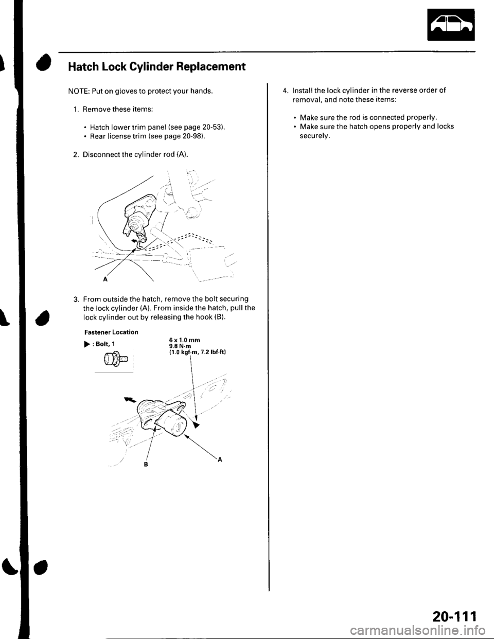
Hatch Lock Cylinder Replacement
NOTE; Put on gloves to protect your hands.
'1. Remove these items:
. Hatch lower trim panel (see page 20-53).. Rear license trim (see page 20-98).
2. Disconnect the cylinder rod (A)
-..
From outside the hatch, remove the bolt securing
the lock cylinder {A}. From inside the hatch, pull the
lock cylinder out by releasing the hook (B).
Fastener Location
> : Bolt, 1
rS'l-.u-ar
6x 1.0 mm9.8Nm(1.0 kgf m,7.2lbt.ftl
*/t
4. Install the lock cylinder in the reverse order of
removal, and note these items:
. Make sure the rod is connected properly.
. Make sure the hatch opens properly and locks
securely.
20-111
Page 766 of 1139
Frame
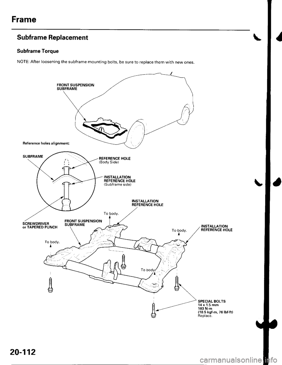
Subframe Replacement
Subframe Torque
NOTE: After loosening the subframe mounting bolts, be sure to replace them with new ones.
Reference holes alignment:
SUBFRAMEREFERENCE HOLE(Body Side)
INSTALLATIONREFERENCE HOLE(Subframe side)
INSTALLATIONREFERENCE HOLE
FRONT SUSPENSIONSCREWDRIVERor TAPERED PUNCHINSTALLATIONREFERENCE HOLE
SPECIAL BOLTS'14 x 1.5 mm103 N.m(10.5 kgf.m,75lbf.ft)Replace.
To body.
To body.I
n
E
20-112
Page 767 of 1139
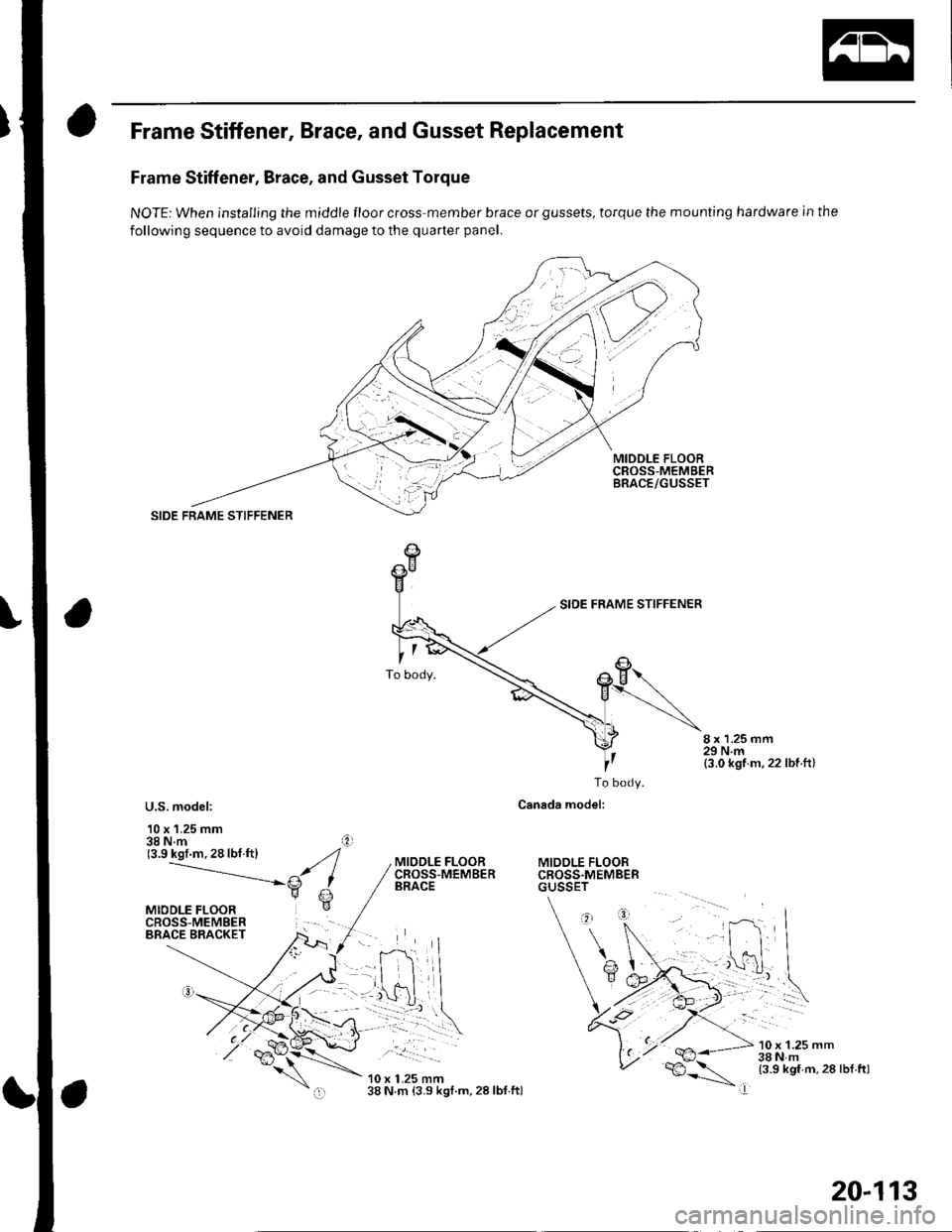
Frame Stiffener, Brace, and Gusset Replacement
Frame Stiffener, Brace, and Gusset Torque
NOTE: When installing the middle floor cross member brace or gussets, torque the mounting hardware in the
following sequence to avoid damage to the quarter panel.
MIDDLE FLOORCROSS-MEMgERBRACE/GUSSET
SIDE FRAME STIFFENER
8 x 1.25 mm29 N.m(3.0 kgf m,22 lbf ft)
U.S. model:
10 x 1.25 mm38 N.m(3.9 kgf.m.28lbf.ftl
To body.
Canada model:
MIDDLE FLOORCROSS.MEMBERGUSSET
MIODLE FLOORCROSS-MEMBERBRACE
.. __!:::-- | -
10 x 1.25 mm38 N m (3.9 kgt.m, 28 lbf.ftl
10 x 1.25 mm38Nm(3.9 kgf.m,28 lbl.ftl
I
20-113
Page 768 of 1139
Frame
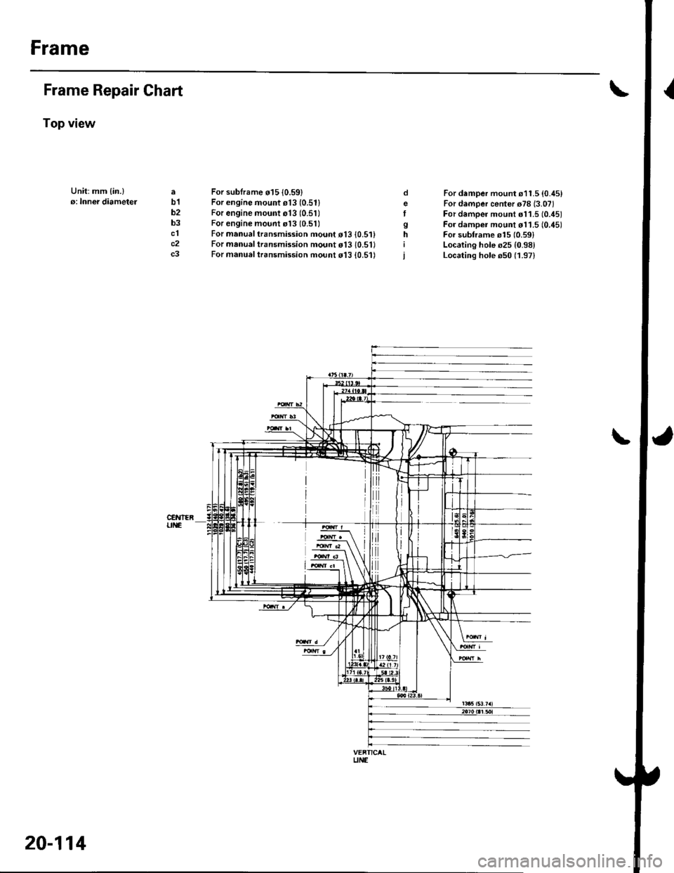
Frame Repair Chart
Top view
Unit:mm {in.}o: Inner diametelab1b2b3clc2c3
For sublrame o15 10.59)For engine mount e13 (0.511
For engine mount o13 (0.51)For engine mount rl3 (0.51)
For manual transmission mouot o13 {0.5'For manual transmission mount o13 10.5'For manual t.ansmission mo!nt d13 {0.51)
o
Igh
For damper mount s11.5 {0.45}For damper center o78 (3.07)
For damper mount s11.5 (0.451
For dampei mount d11.5 10.45)For subframe o15 {0.591Localing hole s25 {0.98}Locating hole e50 (1.97)
\
VEFTICALUNE
20-114
Page 769 of 1139
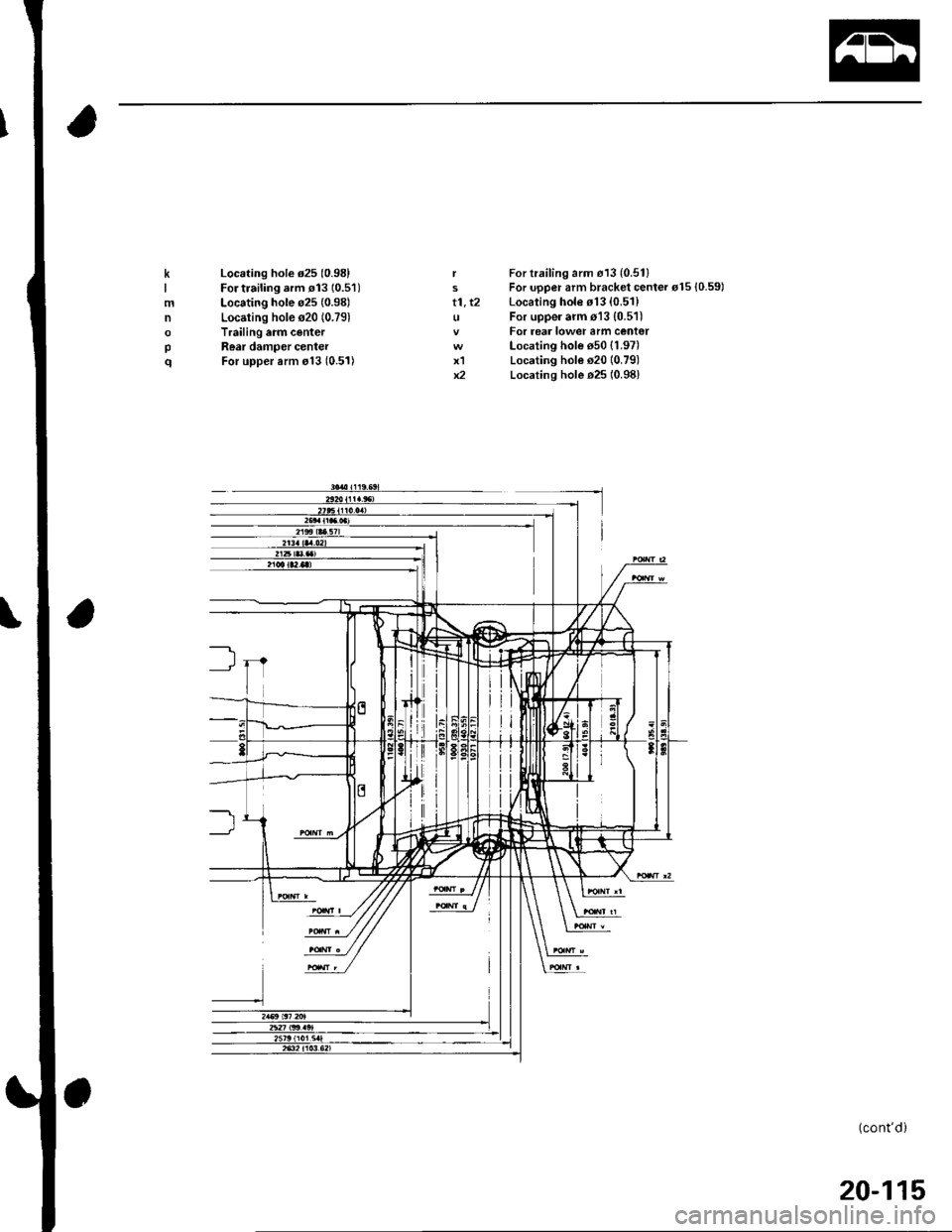
t1, t2
x1x2
K
mn
pq
Locating hole d25 (0.981
For trailing.rm rl3 10.51)Locating hole o25 (0.981
Locating hole s20 (0.79)
Trailing arm centerRear damper centerFor upper arm o13 (0.51)
For trailing arm d13 (0.511
For upper arm bracket center rl5 {0.59)Locating hole s13 (0.51)
For uppe. arm o13 {0.511For rear lower arm cent€rLocating hole s50 (1.97)
Locating hole s20 (0.79)
Locating hole o25 (0.981
(cont'd)
20-115
Page 770 of 1139
Frame
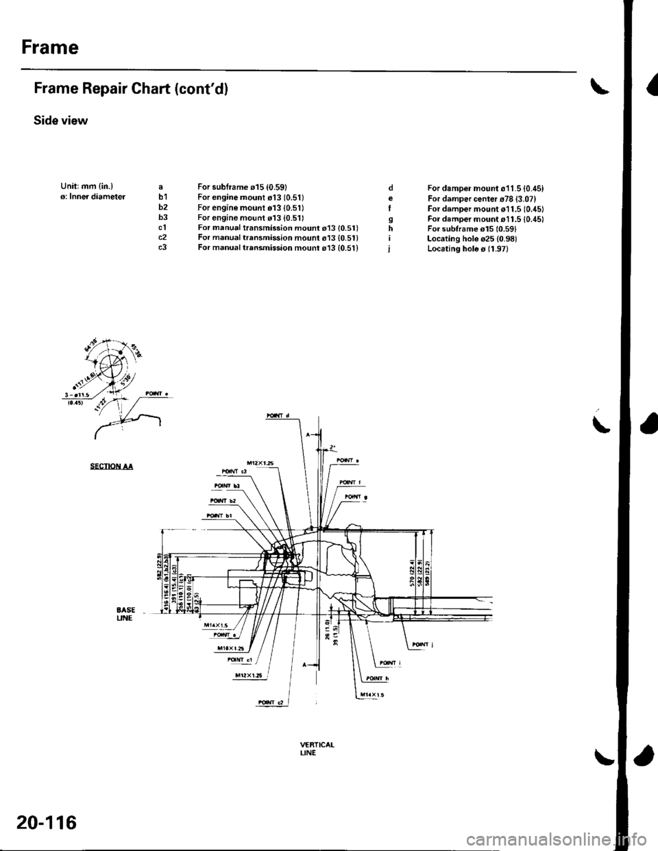
IFrame Repair Chart (cont'dl
Side view
Unitrmm {in.)o: Inner diameteJab1b2b3clc2c3
For subframe 015 {0.59}For engine mount o13 (0.511
For engine mount 01310.51)For engine mount 113 (0.511For manual transmission mount 013 {0.51)For manual trensmission mount 613 {0.51}For manual trrnsmission mounr o13 {0.51}
For damper mount o11.5 {0.45)For damper center r78 {3.07}For damper mount o11.5 (0.45)
For damper mount r11.5 {0./t5lFor subtrame el5 10.591Locating hole o25 (0.98)
Locating hole s 11.97)
oeI
sh
i
\
SECTIOiI AA
BASEUNE
trr2xt.6 l
VERTICAILINE
20-116
Trending: indicator relay, vtc strainer, egr valve, p1505, Wiring, Shock absorber, RECIRCULATION

