Master cylinder HONDA CIVIC 2003 7.G Workshop Manual
[x] Cancel search | Manufacturer: HONDA, Model Year: 2003, Model line: CIVIC, Model: HONDA CIVIC 2003 7.GPages: 1139, PDF Size: 28.19 MB
Page 22 of 1139
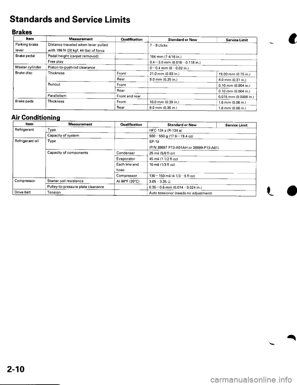
ItemM€asurementOualificationStandard or NewService LimitParking brake
lever
Distance traveled when lever pulled
with 196 N (20 kgf, 44 lbs) ol force
7 8 clicks
Brake pedalPedal height (carpet removed)184 mm (7 4/16 in.)
Free play0.4 3.0 mm (0 016 0 '118 in.)Master cylinderPiston-to-pushrod clearance0 0.4 mm (0 0.02 in.)Erake discThicknessFront21.0 mm (0.83 in.)19.00 mm (0.75 in.)
Rear9.0 mm {0.35 in.)8-0 mm (0.31 in.iRunoutFront0.10 mm (0.004 in.)
Rear0.10 mm (0.004 in.)ParallelismFront and rear0.015 mm (0.0006 in.)Brake padsThicknessFront10.0 mm (0.39 in.)1.6 mm (0.06 in.)
llear9.0 mm {0.35 in.)1.6 mm (0.06 in.)
Standards and Service Limits
Brakes
a
e-o
Air Gonditionin
ItemMoasurementOualilicationStandard or New Service LimitRefrige.antTvpeHFC 134 a (B-134 a)
Capacity of system500 550 g 117.6 19.4 oz)Refrigerant oilTypeSP 1O
(P/N 38897-P13-A01AH or 38899-P13-A01 )Capacity ofcomponentsCondenser25 m0, 15/6 fl ozl
Evaporator45 mA 11 1/2 fl ozt
Each line and
hose
10 m0 (1/3 fl or)
Compressor130 150 m014 1/3 5floz)CompressorStarter coil resistanceAt 68"F (20"C)3.05 3.35 0Pulley-to-pressure plate clearance0.35 0.6 mm (0.014 0.024 in.)Drive beltAuto tensioner lneeds no adjustment)
2-10
q
Page 31 of 1139
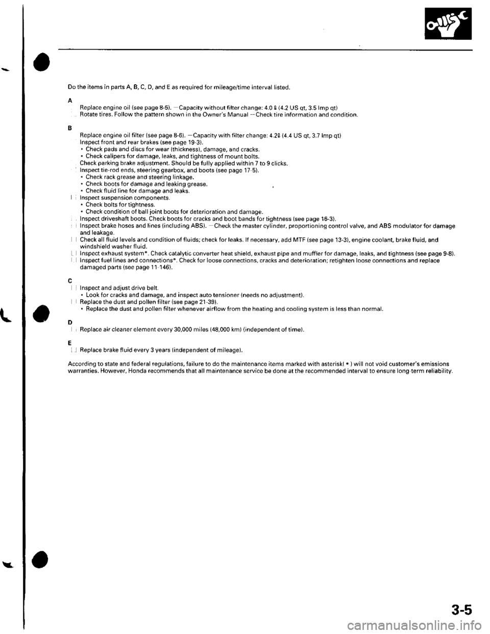
Do the items in parts A, B, C, D, and E as required for mileage/time interval listed.
AReplace engine oillsee page 8-5i. Capacity without lilter change: 4.0 S (4.2 US qt, 3.5 lmp qt)Rotate tires. Follow the pattern shown in the Owner's Manual Checktire information and condition.
BReplace engine oil filter lsee page 8-6). Capacity with filter change: 4.20 (4.4 US qt, 3.7 lmp qt)Inspect front and rear brakes (see page 19 3i.. Check pads and djscs for wear (thickness), damage, and cracks.' Check calipers tor damage, leaks, and tjghtness ot mount bolts.Check parking brake adjustment. Should be Iully applied within 7 to I clicks.Inspect tie rod ends, steering gearbox, and boots {see page 17 5).. Check rack grease and steering linkage.. Check boots for damage and leaking grease. Chack fluid line {or damage and leaks.lnspect suspension components.. Chock bolts fo r tig htness.. Check condition of ball ioint boots lor deterioration and damage.Inspect driveshaft boots. Check boots for cracks and boot bands for tightness (see page 16-3).Insp€ct brake hoses and lines {including ABS). Checkthe mastercylinder, proponioning control valve, and ABS modulator{or damageand leakage.Check all fluid levels and condition ot tluids; check for leaks. lf necessary, add MTF lsee page 13'3), engioe coolant, brake fluid, and
Lwindshield washer fluid.lnspectexhaust system*. Check catalytic converter heatshield, exhaust pipe and mufflerfordamage,leaks, and tightness {soe page 9,8).lnspect {uel lines and connections*. Check for loose connections, cracks and deterioration; retighten loose connoctions and replacedamaged parts (s€e page 11 146).
InsDect and adiust drive belt.. Look for cracks and damage, and inspect auto tensioner (needs no adjustment).Replace the dust and pollen lilter (see page 21 39).. Replacethe dustand pollen filter whenever airf low lrom the heating and cooling system is lessthan normal.
Replace air cleaner element every 30,000 miles (48,000 km) (independent of time).
l
D
Ei I Replace brake fluid every 3 years (independent oI mileage).
According to state and federal regulations, failure to do the maintenance items marked with asterisk( * ) will not void customer's emissionswarranties. However, Honda recommends that all maintsnance service be done at the recommended interval to ensure long term reliability.
Y
3-5
Page 33 of 1139
L
A
I
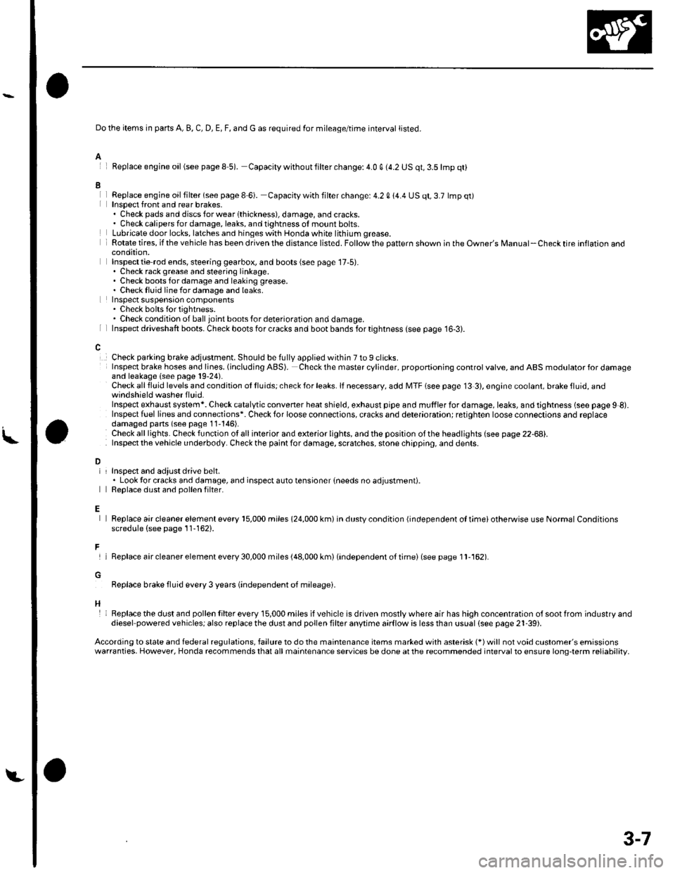
Do the items in parts A, B, C, D, E, F, and G as required for mileage/time interval listed.
Feplace engine oil(see pageS 5). Capacity withoutlilter change:4.0 q (4.2 US qt,3.5lmp qt)
Replace engjne oil filter (see page I 6). Capacity with filter change: 4.2 0 14.4 US qt, 3.7 lmp qt)Insoect front and rear brakes,. Check pads and discsforwearlthickness), damage, andcracks.. Check calipers for damage, leaks, and tightness of mount bolts.Lubricate door locks, latches and hinges with Honda white lithium grease.Rotate tires, if the vehicle has been driven the distance listed. Follow the pattern shown in the Owner's Manual-Check tire inflaron aoocondition,Inspecttie rod ends, steering gearbox, and boots (see page 17,5).. Check rack grease and steering linkage.. Check boots for damage and leaking grease.. Checklluid linefordamage and leaks.Inspect suspensron components. Check bolts for tightness.. Check condition of ball joint boots for deterioration and damage.Inspect driveshaft boots. Check boots for cracks and boot bands for tightness (see page 16-3).
Check parking brake adjustment. Should be fully applied within 7 to 9 clicks.Insp€ct brake hoses and lioes. (including ABS). Check the master cylinder, proportioning control valve, and ABS modulator for damageand leakage (see page 19-24).Check all fluid levels and condition ot lluids; check for leaks. lf necessary, add MTF (see page 13 3), engine coolant, brake fluid, andwindshield washer f luid.Inspect exhaust system*. Check catalytic converter heat shield, exhaust pipe and muffler for damage, leaks, and tightness (see page 9 8).Inspect fuel lines and connections*. Check for loose connections, cracks and deterioration; retighten loose connections and replacedamaged pans (seo page 11'146).Check alllights. Checkfunction otallinterior and exterior lights, andthe position ofthe headlights (see page 22-68).Inspect the v€hicle underbody. Check the paint for damage, scratches, stone chippin0, and dents.
L
D
E
F
H
InsDect and adiust drive belt.. Look tor cracks and damage, and inspect auto tensioner {needs no adjustment).Reolace dust and oollen filter.
Replace air cleaner element every 15,000 miles 124,000 km) in dustv condition {independent ol timei otherwise use Normal Conditionsscredule (see page 11-162).
lReplaceaircleanerelementevery30,000miles(48,000km)(independento{timei(seepagell-162).
Replace brake fluid every 3 years (independent oJ mileagei.
Replacethe dust and pollen Iilter every 15,000 miles ifvehicle is driven mostlywhere air has high concentration olsootfrom industryanddiesel powered vehiclesj also replace the dust and pollen filter anytime aarflow is less than ussal (see pags 21-39).
According to state and federal regulations, failure to do the maintenance items marked with asterisk (*) will not void customer's emissionswarranties. However, Honda recommends that all maintenance services be done at the recommended interval to ensure long-term reliability,
3-7
Page 398 of 1139
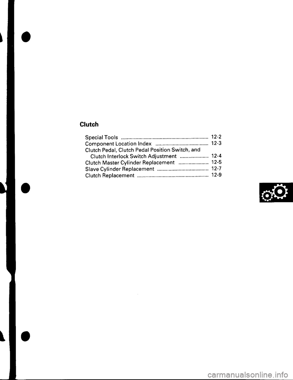
Clutch
Special Tools ......... 12-2
Comoonent Location Index .......................,............. 12-3
Clutch Pedal, Clutch Pedal Position Switch, and
Clutch Interlock Switch Adiustment .................... 12-4
Cf utch Master Cylinder Rep|acement ..................... 12-5
Slave Cylinder Replacement .'........ 12-7
Clutch Replacement ................... ..... 12-9
Page 400 of 1139
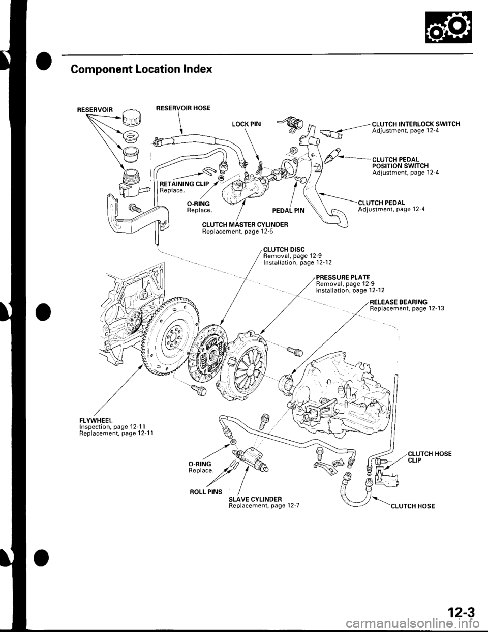
Component Location Index
""*--/\,L_.Ei
/i
(,'.'
CLUTCH INTERLOCK SWITCHAdjustment, page 12-4
CLUTCH PEDALPOSTTTON SWITCHAdjustment, page'12-4
RETAINING CLIPReplace.
_,___-,-s\
O-RINGReplace.UTCH PEDALAdjustment, Page 12 4
CLUTCH MASTER CYLINDERReplacement, page l2-5
CLUTCH DISCBemoval, page 12-9Installation, page'12-12
PRESSURE PLATERemoval, page'12-9lnstallation, page 12-12
FLYWHEELInspection, page'12-1 1Replacement, page 12-1 1
SLAVE CYLINDERReplacement, page 12-7
RELEASE BEARINGBeplacement, page 12-13
\".rr"*"o*
CLUTCH HOSECLIP
12-3
Page 401 of 1139
Clutch
Clutch Pedal, Clutch
Adjustment
NOTE:. To check the clutch pedal position switch(see page 4-45).. To check the clutch interlock switch (see page 4-6).. Remove the driver's side floor mat before adjusting
the clutch pedal.. The clutch is self-adjusting to compensate for wear.. lf there is no clearance betweenthe mastercylinderpiston and push rod, the release bearing will be held
against the diaphragm spring. which can result in
clutch slippage or other clutch problems.
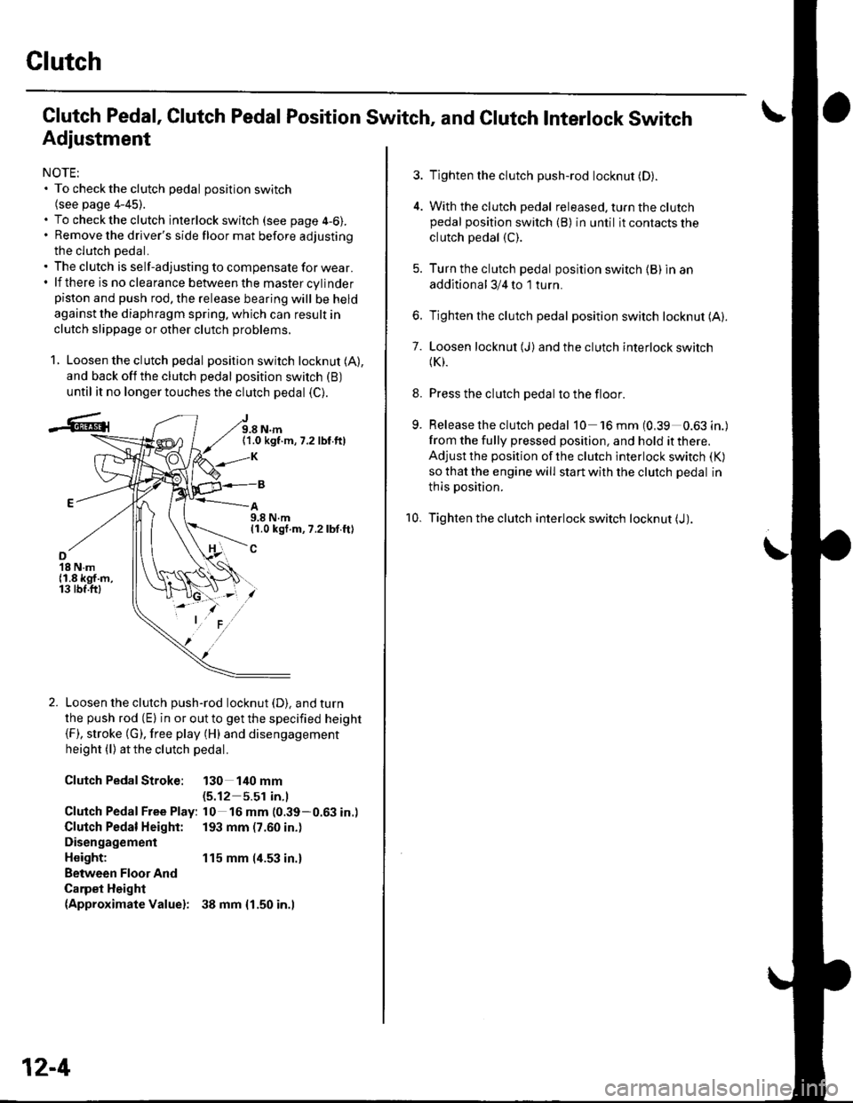
1. Loosen the clutch pedal position switch locknut (A),
and back off the clutch pedal position switch (B)
until it no longer touches the clutch pedal (C).
J9.8 N.m(1.0 kgf.m,7.2 lbf.ft)
A9.8 N.m11.0 kgf.m, 7.2 lbf.ft)
o18 N.m{1.8 kgf.m,13 tbf.ftl
Loosen the clutch push-rod locknut (D). and turn
the push rod (E) in or out to get the specified height(F), stroke (G). free play (H) and disengagement
height (l) atthe clutch pedal.
Clutch PedalStroke: 130 140 mm(5.12 5.51 in.l
Clutch Pedal Free Play: l0 16 mm (0.39-0.63 in.)
Clutch Pedal Height: 193 mm (7.60 in.)
Disengagement
Height: 115 mm (4.53 in.)
Between Floor And
Carpet Height(Approximate Valuel: 38 mm {1.50 in.l
12-4
Pedal Position Switch, and Clutch Interlock Switch
3. Tighten the clutch push-rod locknut (D).
4. With the clutch pedal released. turn the clutchpedal position switch (B) in until it contacts the
clutch pedal (C).
5. Turn the clutch pedal position switch {B) in an
additional 3/4 to 1 turn.
6. Tighten the clutch pedal position switch locknut (A).
7. Loosen locknut (J)and the clutch interlock switch(K).
8. Press the clutch pedal to the floor.
9. Release the clutch pedal 10 'l6mm(0,39 0.63in.)
from the fully pressed position, and hold it there.
Adjust the position of the clutch interlock switch (K)
so that the engine will start with the clutch pedal in
thls position.
10. Tighten the clutch interlock switch locknut (J).
Page 402 of 1139
Clutch Master Cylinder Replacement
NOTE: Do not spill brake fluid on the vehicle; it may
damage the paint; if brake fluid does contact the paint,
wash it off immediatelV with water.
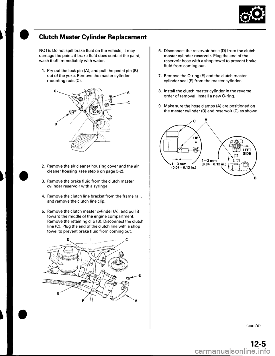
1. Pry out the lock pin (A), and pullthe pedal pin (B)
out of the yoke. Remove the master cylinder
mounting nuts (C).
Remove the air cleaner housing cover and the air
cleaner housing (see step 6 on page 5-2).
Remove the brake fluid from the clutch master
cylinder reservoir with a syringe.
Remove the clutch line bracket from the frame rail,
and remove the clutch line clip.
Remove the clutch master cylinder (A), and pull it
toward the middle of the engine compartment.
Remove the retaining clip (B). Disconnect the clutch
line (C). Plug the end of the clutch line with a shop
towelto prevent brake fluid from coming out.
g-E
3.
6. Disconnect the reservoir hose (D) fromtheclutch
master cylinder reservoir. Plug the end of the
reservoir hose with a shop towel to prevent brake
fluid from coming out.
7. Remove the O-ring (E) and the clutch master
cylinder seal (F) from the master cylinder.
8. Installthe clutch master cylinder in the reverse
order of removal. Install a new O-ring.
9. Make sure the hose clamps (A) are positioned on
the master cylinder (B) and reservoir (C) as shown.
(cont'd)
UP
i
12-5
Page 403 of 1139
Clutch
Clutch Master Cylinder Replacement (cont'd)
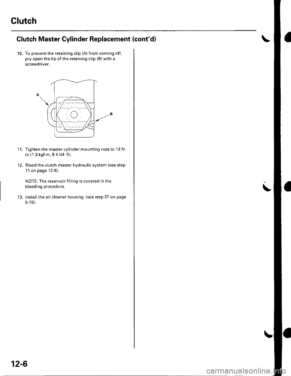
10. To prevent the retaining clip (A) from coming off,
pry open the tip of the retaining clip (B) with a
screwdriver,
Tighten the master cylinder mounting nuts to 13 N
m (1.3 kgf m, 9.4 lbf.ft).
Bleed the clutch master hydraulic system (see step
1 1 on page 12-8).
NOTE: The reservoir filling is covered in the
bleeding procedure.
lnstallthe air cleaner housing (see step 37 on page
5-15).
11.
12-6
I
Page 405 of 1139
Clutch
Slave Cylinder Replacement (cont'd)
11. Bleed the clutch hydraulic system.
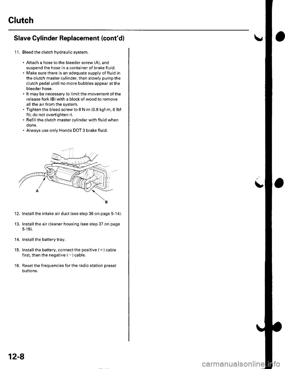
. Aftach a hose to the bleeder screw (A), and
suspend the hose in a container of brake fluid.. Make sure there is an adequate supply offluid in
the clutch master cylinder, then slowly pump the
clutch pedal until no more bubbles appear atthe
bleeder hose.. lt may be necessary to llmit the movement of the
release fork (B) with a block of wood to remove
all the air from the system.. Tighten the bleed screw to I N.m (0.8 kgf.m, 6 lbf
ft); do not ovenighten it,. Refill the clutch master cylinder with fluid when
done.. Always use only Honda DOT 3 brake fluid.
Install the intake air duct (see step 36 on page 5-14).
Installthe air cleaner housing (see step 37 on page
5-15).
Install the battery tray.
Install the battery, connect the positive (+) cable
first, then the negative (- ) cable.
Reset the frequencies for the radio station preset
buttons,
12.
13.
14.
t5.
16.
12-8
L
Page 545 of 1139
EPS Components
Steering Gearbox Removal {cont'd)
22. Move the steering gearbox and tie-rod ends as anassembly to the wheelwell opening on thepassenger's side.
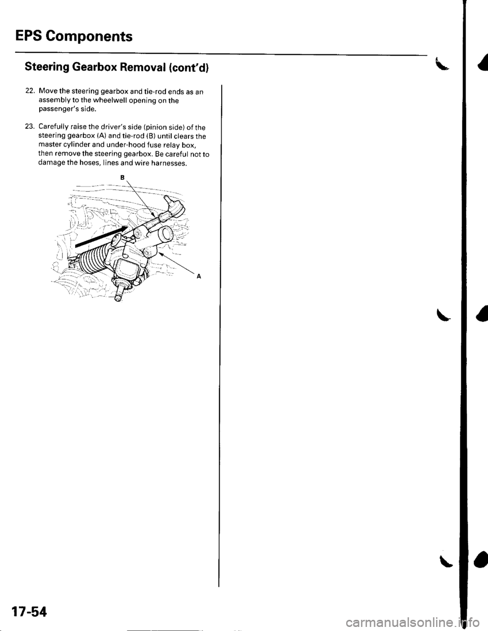
23. Carefully raise the driver's side (pinion side) ofthesteering gearbox (A) and tie-rod (B) until clears themaster cylinder and under-hood fuse relay box,
then remove the steering gearbox. Be careful not to
damage the hoses, lines and wtre narnesses.
17-51