radiator replace HONDA CIVIC 2003 7.G Workshop Manual
[x] Cancel search | Manufacturer: HONDA, Model Year: 2003, Model line: CIVIC, Model: HONDA CIVIC 2003 7.GPages: 1139, PDF Size: 28.19 MB
Page 52 of 1139
lgnition Timing Inspection
1.
4.
5.
Connect the Honda PGM Tester to the data link
connector (DTC), and check for DTC'S. lf a DTC is
present, diagnose and repair the cause before
inspecting the ignition timing.
Startthe engine. Hold the engine at 3,000 rpm with
no load (in Neutral) until the radiator fan comes on,
then let it idle.
Check the idle speed (see page 11-138).
Follow the tester's prompts in the "SCS" menu
{see the tester operator's manual),
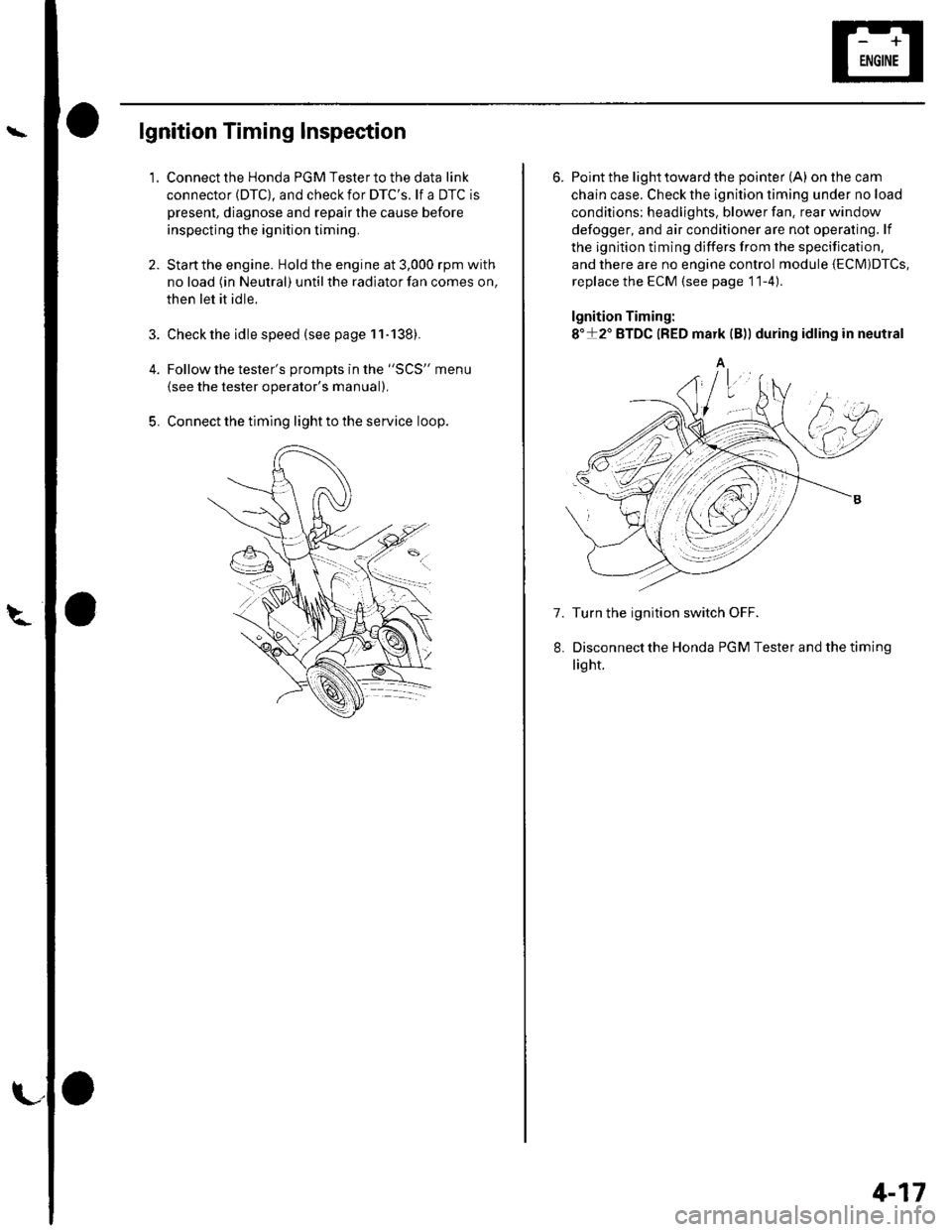
Connect the timing light to the service loop.
o
6. Point the light toward the pointer (A) on the cam
chain case. Check the ignition timing under no load
conditions: headlights, blower fan. rear window
defogger, and air conditioner are not operaling. lf
the ignition timing differs from the specification,
and there are no engine control module {ECM)DTcs,
replace the ECM (see page 11-4)
lgnition Timing:
8"+2" BTDC {RED mark {B)) during idling in neutral
A
7. Turn the ignition switch OFF.
Disconnectthe Honda PGM Tester and thetiming
light.
4-17
Page 59 of 1139
Gharging System
Charging Circuit Troubleshooting (cont'd)
6. Start the engine. Hold the engine at 3,000 rpm with
no load (in Neutral) until the radiator fan comes on,
then let it idle.
7. Raise the engine speed to 2,000 rpm, and hold it
there.
8. Turn the headlights (high beam) on, and measure
voltage at the under-hood fuse/relay box terminal.
ls the voltage between 13.9 and 15.1 v?
YES-Go to step 9.
NO Repair or replace the alternator components
(see page 4-30).1
9. Read the amperage at '13.5 V.
NOTE: Adjust the voltage by turning the blower
motor, rear window defogger, brake lights. etc. ON.
ls the amperage 604 ot morc?
YES-Alternator/regulator operation is OK. I
NO Repair or replace the alternator components(see page 4-30).1
4-24
\,
Alternator Control System Test
NOTE: After troubleshooting, perform the engine
control module (ECM) idle learn procedure (see page
11-139).
1 . Check for proper operation of the electrical load
detector (ELD) by checking the malfunction
indicator lamp (MlL) (see page 1 l-3). lf a DTC is
present, diagnose and repair the cause before
continuing with this test.
2. Disconnect the engine wire harness 6P connector
from the starter sub harness 6P connector.
3. Start the engine, and turn the headlights (high
beam) ON,
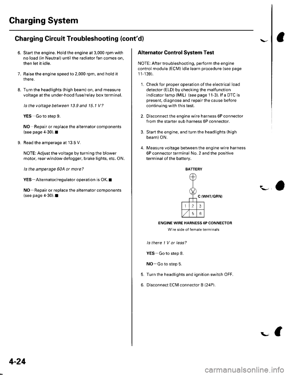
4. Measure voltage between the engine wire harness
6P connector terminal No. 2 and the positive
terminal of lhe battery.
C {WHT/GRN)
ENGINE WIRE HARNESS 6P CONNECTOR
Wire side of female terminals
ls there 1 V or less?
YES Go to step 8.
NO-Go to step 5.
Turn the headlights and ignition switch OFF.
Disconnect ECM connector B (24P).
5.
6.
BATTERY
Page 191 of 1139
Engine Cooling
Cooling System
Component Location Index ......................................... 10-2
Radiator Cap Test ..................... .......... 10-3
RadiatorTest ............. 10-3
Fan Motor Test .......... l0-4
Thermostat Test ...................... ........... 10-4
Water Pump Inspection ..................... 10-5
Water Pump Replacement ................. 10-5
Coolant Check .............. ....................... 10-6
Coolant Replacement ......................... 10-6
Thermostat Replacement .................. 10-8
Water Passage Installation ................ 10-9
Water Outlet Installation .................... 10-9
Radiator and Fan Replacement ................................... 10-10
Fan Controls
Component Location Index ......................................... 10-11
Symptom Troubleshooting Index ............................... 10-12
Circuit Diagram ......... 10-13
Radiator Fan CircuitTroubleshooting ........................ 10-14
Radiator Fan Switch Circuit Troubleshooting
(Open) ............ ........ 10-16
Radiator Fan Switch Circuit Troubleshooting
(Short) ............ ........ 10-16
Radiator Fan Switch Test ................... 10-17
Radiator Fan Switch Reolacement .............................. 10-17
Page 192 of 1139
Cooling System
Component Location Index
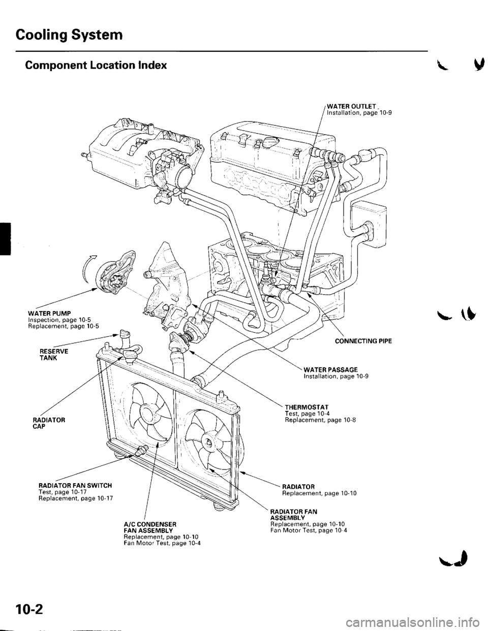
WATER PUMPInspection, page 10-5Replacement. page 10-5
RESERVETANK
RADIATORCAP
RAOIATOR FAN SWITCHTest, page 10-17Replacement, page 10'17
\
WATER OUTLET,Installation, page'10-g
\f
CONNECTING PIPE
WATER PASSAGEInstallation, page 10-9
THERMOSTATTest, page 10 4Replacement, page 10 8
RADIATORReplacement, page 10-'l0
RADIATOR FANASSEMgLYReplacement, page 10-10Fan MotorTest, page 10 4A/C CONDENSERFAN ASSEMBLYReplacement, page 10 10Fan Motor Test, page '10-4
10-2
\J
Page 193 of 1139
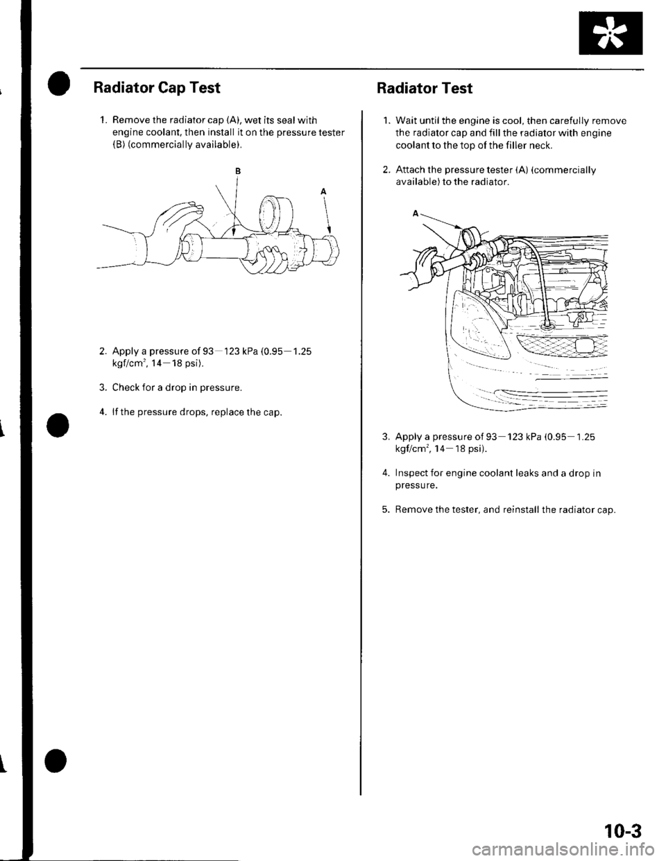
Radiator Cap Test
1. Remove the radiator cap {A), wet its seal with
engine coolant, then install it on the pressure tester(B) (commercially available).
Apply a pressure of 93 '123 kPa {0.95 1.25
kgf/cm', l4 18 psi).
Check for a drop in pressure.
lf the pressure drops, replace the cap.
3.
4.
Radiator Test
Wait untilthe engine is cool, then carefully remove
the radiator cap and fill the radiator with engine
coolant to the top of the filler neck.
Attach the pressure tester (A) (commercially
available) to the radiator.
1.
3.
4.
Apply a pressure ot 93 '123 kPa (0.95 1 .25
kgf/cm', '14 18 psi).
Inspect for engine coolant leaks and a drop in
pressu re.
Remove the tester, and reinstall the radiator cap.
10-3
Page 194 of 1139
Cooling System
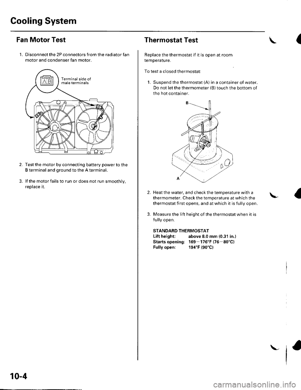
Fan Motor Test
1. Disconnect the 2P connectors from the radiator fan
motor and condenser fan motor.
Test the motor by connecting battery power to the
B terminal and ground to the A terminal.
lf the motor fails to run or does not run smoothly,
reptace rL
10-4
\
Thermostat Test
Replace the thermostat if it is open at room
remperalure.
To test a closed thermostatl
1. Suspend the thermostat (A) in a container of water.
Do not let the thermometer {B) touch the bottom of
the hot container.
(\
2.
3.
Heat the water, and check the temDerature with a
thermometer. Check the temperature at which the
thermostat first opens, and at which it is fully open.
Measure the lift height of the thermostat when it is
fullv ooen.
STANDARD THERMOSTAT
Lift height; above 8.0 mm (0.31 in.)
Starts opening: 169 176"F(76 80"C)
Fully open: 194"F {90'Cl
\.
Page 195 of 1139
1.
2.
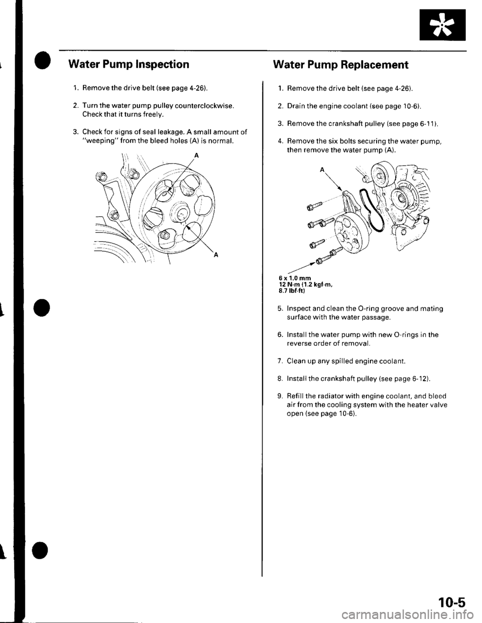
Water Pump Inspection
Remove the drive belt (see page 4-26),
Turn the water pump pulley counterclockwise.
Check that it turns freely.
Check for signs of seal leakage. A small amount of"weeping" from the bleed holes (A) is normal.
Water Pump Replacement
1. Remove the drive belt (see page 4-26).
2. Drain the engine coolant {see page 10-6).
3. Remove the crankshaft pulley (see page 6-11).
4. Remove the six bolts securing the water pump,
then remove the water pump (A).
6x1.0mm12 N m {1.2 kgt m,8.7 rbf.ft)
Inspect and clean the O-ring groove and mating
surface with the water passage.
Installthe water pump with new O rings in the
reverse order of removal.
7. Clean up any spilled engine coolant.
8. Installthe crankshaft pulley (see page 6-12).
L Refill the radiator with engine coolant, and bleed
air from the cooling system with the heater valve
open {see page 10-6}.
10-5
Page 196 of 1139
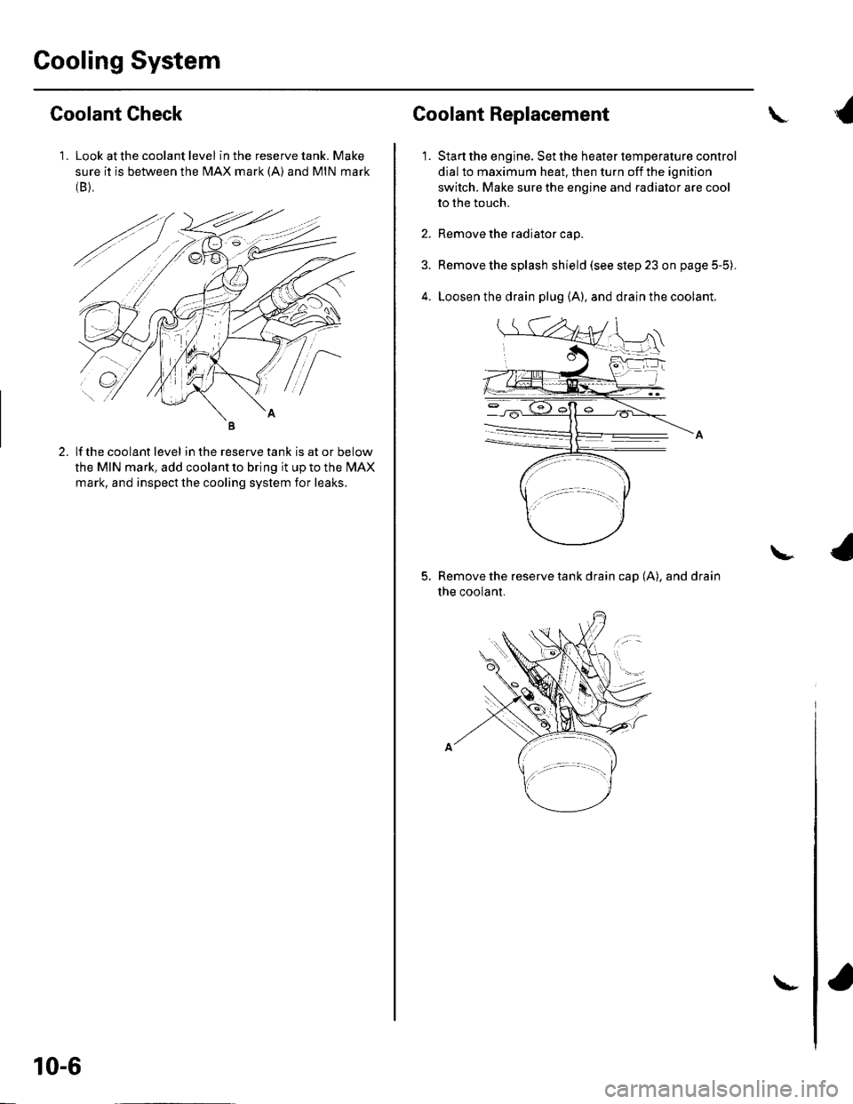
Cooling System
1 . Look at the coolant level in the reserve tank. Make
sure it is between the MAX mark (A) and MIN mark(B),
Goolant Check
lf the coolant level in the reserve tank is at or below
the MIN mark, add coolant to bring it up to the l\4AX
mark, and inspect the cooling system for leaks.
10-6
\-
Coolant Replacement
1.
\
Start the engine. Set the heater temperature control
dial to maximum heat. then turn off the ignition
switch. Make sure the engine and radiator are cool
to the touch.
Remove the radiator cap.
Remove the splash shield (see step 23 on page 5-5).
Loosen the drain plug (A), and drain the coolant.
Remove the reserve tank drain cap (A), and drain
the coolant.
\
Page 198 of 1139
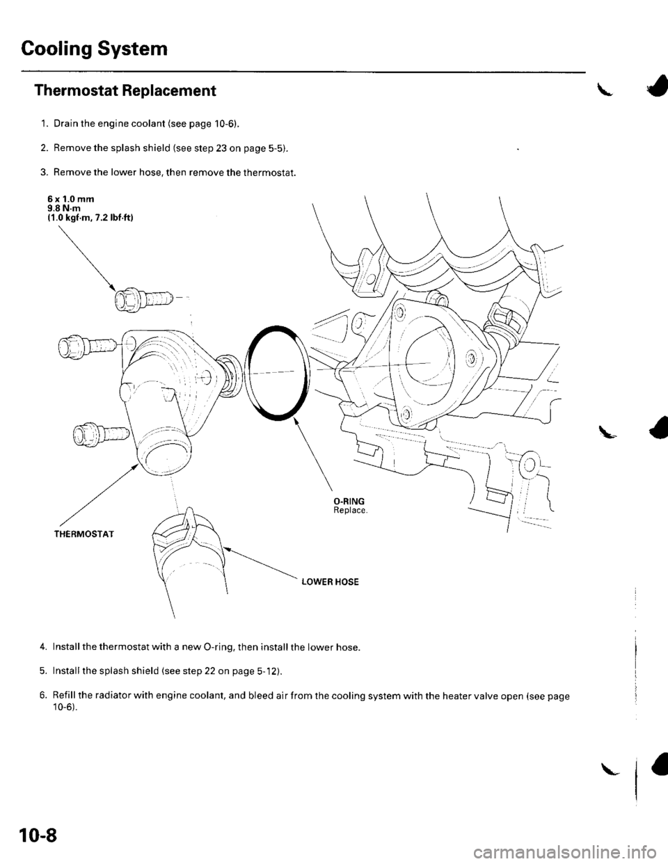
Gooling System
Thermostat Replacement
1. Drain the engine coolant (see page 10-6).
2. Remove the splash shield (see step 23 on page 5-5).
3. Remove the lower hose, then remove the thermostat.
6x 1.0 mm9.8 N.m(1.0 kgf.m,7.2lbf ft)
a
u
i*
-
LOWER HOSE
4. Installthe thermostat with a new O-ring, then installthe lower hose.
5. Installthe splash shield (see step 22 on page 5-12).
6. Refillthe radiator with engine coolant, and bleed air from the cooling system with the heater valve open (see page
10_6).
THERMOSTAT
10-8
\_
Page 200 of 1139
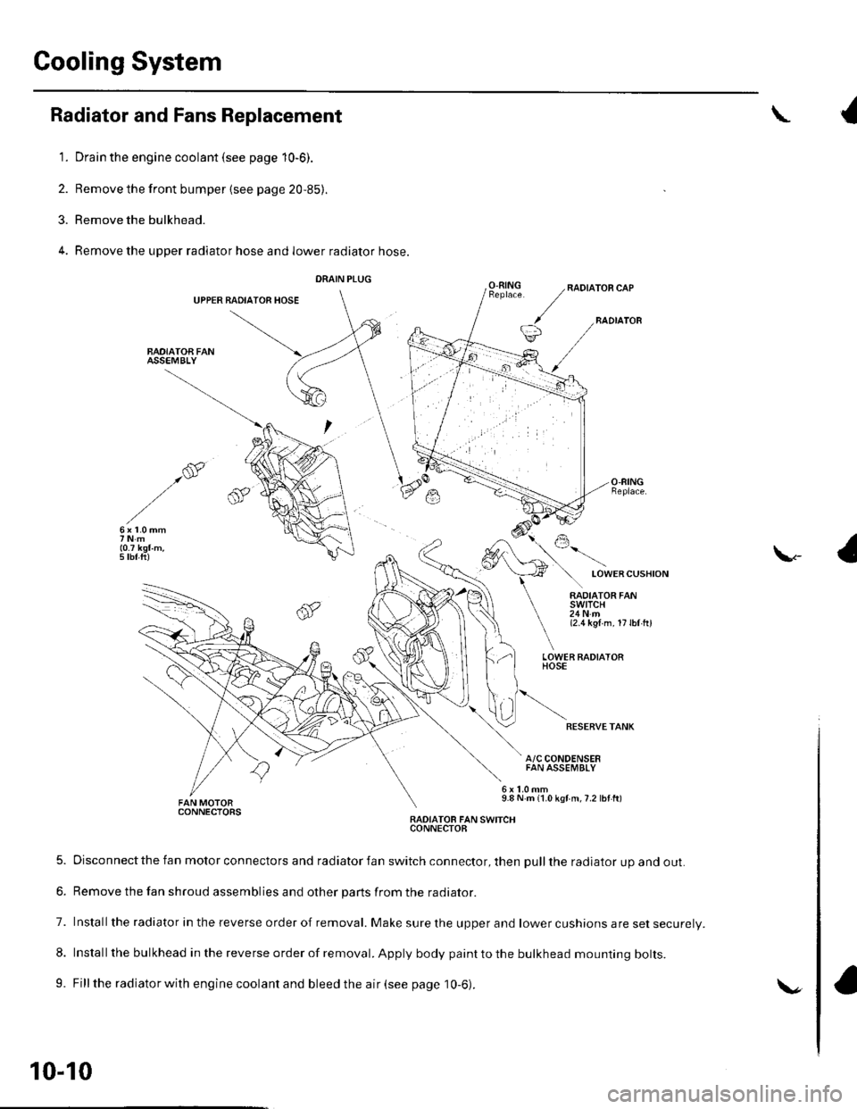
Cooling System
Radiator and Fans Replacement
1. Drain the engine coolant (see page 10-6).
2. Remove the front bumper {see page 20,85).
3. Remove the bulkhead.
4. Remove the upper radiator hose and lower radiator hose.
DRAIN PLUG
UPPER BADIATOR HOSE
BAOIATOA FANASSEMBLY
{
O.RINGRADIATOR CAP
BADIATOB
LOWERCUSHION
\-
RADIATOR FANswtTcH24Nm{2.1t kgl m. 17lbl hl
LOWER FADIATORHOSE
RESERVETANK
A/C CONDENSERFAN ASSEMBLY
9.8 N m {1.0 kgf m,7.2 lbf ft)CONNECTORSRADIATOB FAN SWITCHCONNECTOB
5. Disconnect the fan motor connectors and radiator fan switch connector, then pull the radiator up and out.
6. Remove the fan shroud assemblies and other parts from the radiator.
7. Installthe radiator in the reverse order of removal. Make sure the upper and lower cushions are set securelV.
8. Install the bulkhead in the reverse order of removal. Apply body paint to the bulkhead mounting bolts.
9. Fill the radiator with engine coolant and bleed the air (see page 10-6).
10-10
\.