Mounting HONDA CR-V 1997 RD1-RD3 / 1.G User Guide
[x] Cancel search | Manufacturer: HONDA, Model Year: 1997, Model line: CR-V, Model: HONDA CR-V 1997 RD1-RD3 / 1.GPages: 1395, PDF Size: 35.62 MB
Page 123 of 1395
Timing Belt
Removal
Replace the timing belt at 105,000 miles (168,000 km)
according to the maintenance schedule {normal condi-
tions/severe conditions). lf the vehicle is regularly driven
in either of the following conditions, replace the timing
belt at 60,000 miles (U.S.A.l 100.000 km (Canada).
- ln very high temperatures (over 110'F, 43"C).- In very low temperatures (under -20"F. -29"C).
Turn the crankshaft pu\ley so the No. 1 piston is at
top dead center (TDC).
Remove the guard bar and splash shield (see page
5-7 ).
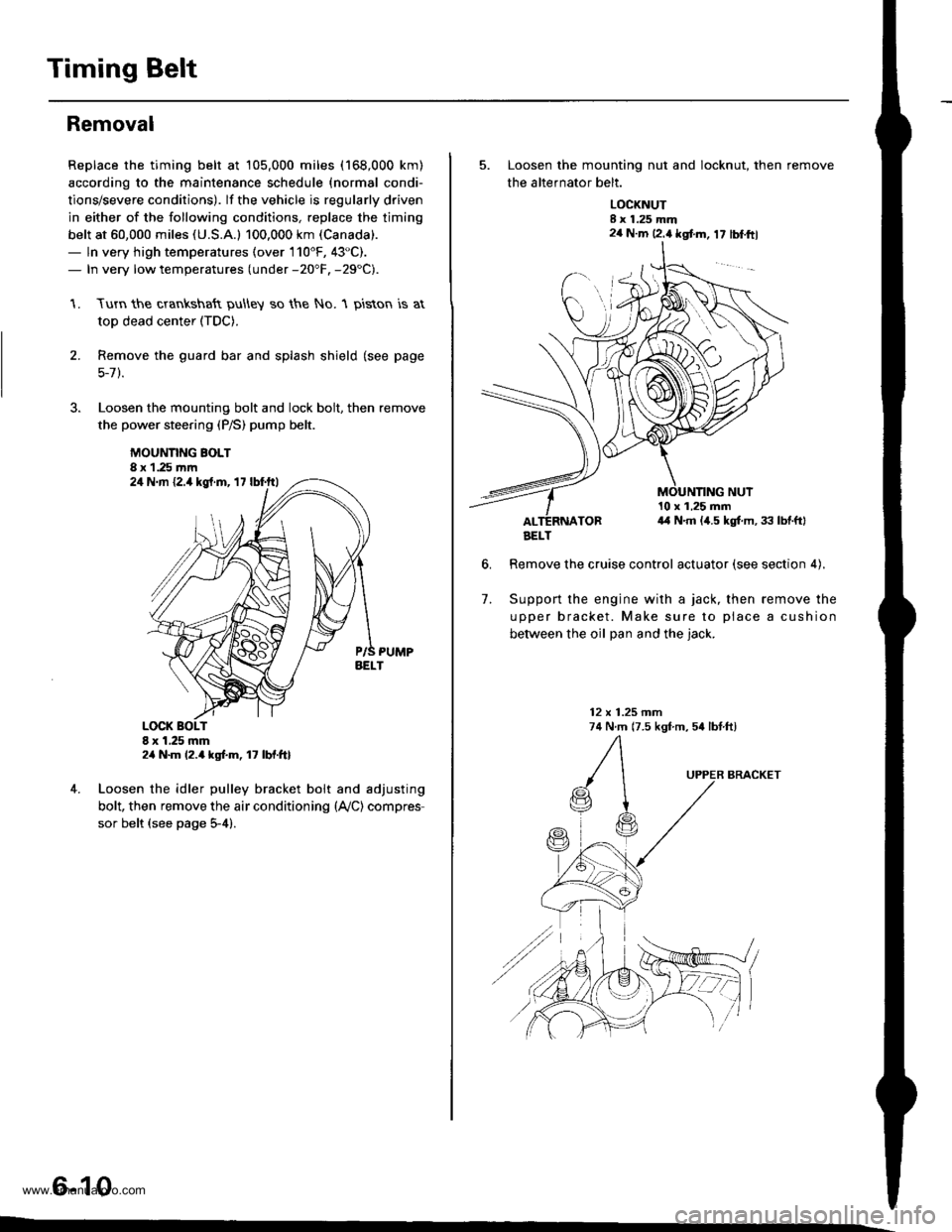
Loosen the mounting bolt and lock bolt. then remove
the power steering (P/S) pump belt.
MOUNNNG BOLT8 x 1.25 rnm
1.
2.
,l
4. Loosen the idler pulley bracket bolt and adjusting
bolt, then remove the air conditioning (lVC) compres
sor belt (see page 5-4).
6-10
24 N.m {2.4 kgt.m, 17 lbf.ftl
24 N.m 12.4 kgf.m, lt lbf.ftl
5. Loosen the mounting nut and locknut, then remove
the altefnator belt.
LOCKNUTI x 1.25 mm2a N.m 12.4 kgt m, 17 lblftl
6.
10 x 1,25 mm4,1 N.m (,1.5 kgt m, 33 lbtftl
Remove the cruise control actuator (see section 4).
Support the engine with a jack, then remove the
upper bracket. Make sure to place a cushion
between the oil Dan and the iack.
12 x 1.25 mm74 N.m (7.5 kgf m, 54 lbtftl
7.
BRACKET
AELT
www.emanualpro.com
Page 126 of 1395
CKF Sensor
Replacement
1.
|o|'ln PUUCY BMCKET SOLIl0 r 1.25 mm14 .m 14.5 kgl.m,3:' lbtftl
Remove the guard bar and splash shield (see page
5-7 t.
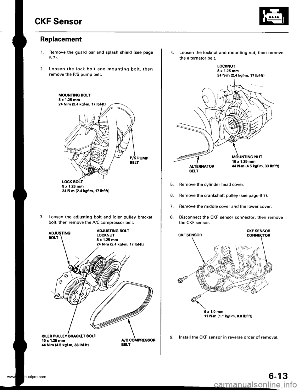
Loosen the lock bolt and mounting bolt, then
remove the P/S pump belt.
MOUNTING BOLT8 x 1.25 mm
PUMPBELT
Loosen the adjusting bolt and idler pulley bracket
bolt, then remove the Ay'C comDressor belt.
ADJUSTING BOLTLOCKNUT8 x 1.25 mm24 N.m {2.4 kgf.m, 17 lbf.ft)
24 N.m (2.{ kgf.m, 17 lbf.ttl
24 N.m 12.4 lgf.m, 17 lbl.ftl
4. Loosen the locknut and mounting nut, then remove
the alternator belt.
LOCKNUT8 x 1.25 mm24 N.m (2.4 kgl.m, 17 lbtftl
10 x 1 .25 mma4 N.m (4.5 kgt m, 33 lbtft)
E
6.
7.
aJ.
Remove the cylinder head cover.
Remove the crankshaft pulley (see page 6-7).
Remove the middle cover and the lower cover.
Disconnect the CKF sensor connector, then remove
the CKF sensor.
6x1.0mm11 N.m {1.r kgnm,8.0 lbfft)
9. Install the CKF sensor in reverse order of removal.
BELT
CKF SENSOR
6-13
www.emanualpro.com
Page 129 of 1395
Gylinder Head
Removal
Engine removal is not required for this procedure.
l!@ Make sure iacks and safety stands are
placed properly, and hoist blackels ale attachgd to the
correct position on the engine.
NOTE:
o Use fender covers to avoid damaging painted sur-
faces.
o To avoid damage, unplug the wiring connectors care-
fully while holding the connector portion.
. To avoid damaging the cylinder head, wait until the
engine coolant temperature drops below 100"F (38'C)
before loosening the retaining bolts.
. Mark all wiring and hoses to avoid misconnection.
Also, be sure that they do not contact other wiring or
hoses, or interfere with other parts.
2.
4.
5.
1.Disconnect the negative terminal from the battery.
Drain the engine coolant (see page 10-5). Remove
the radiator cap to speed draining.
Remove the intake air duct and air cleaner housing(see page 5-2).
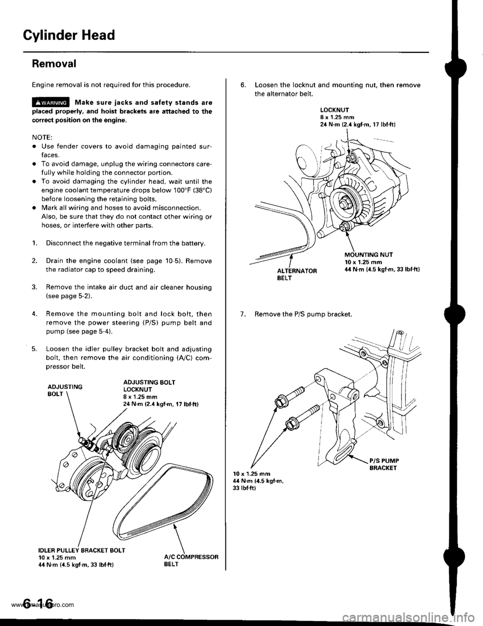
Remove the mounting bolt and lock bolt, then
remove the power steering (P/S) pump belt and
pump (see page 5-4).
Loosen the idler pulley bracket bolt and adjusting
bolt, then remove the air conditioning (A,/C) com,
pressor belt.
ADJUSTINGBOLT
ADJUSTING BOLTLOCKNUT8 x 1.25 mm24 N m {2.4 ksf.m, 17 lbttt}
IOLER PULLEY BBACKET BOLT10 x 1.25 mm44 N.m {4.5 kgtm, 33 lbf ft)
tt aAo-Io
6. Loosen the locknut and mounting nut, then remove
the alternator belt.
LOCKNUT8 x 1.25 mm24 N.m (2.4 kgf.m, 17 lbt.ftl
10 x 1.25 mm44 N.m (4.5 kgt.m. 33 lbf.ft)
7. Remove the P/S OUmo bracket.
l0 x 1.25 mm44 N.m (4.5 kgf.m,33 rbf.ft)
BELT
www.emanualpro.com
Page 134 of 1395
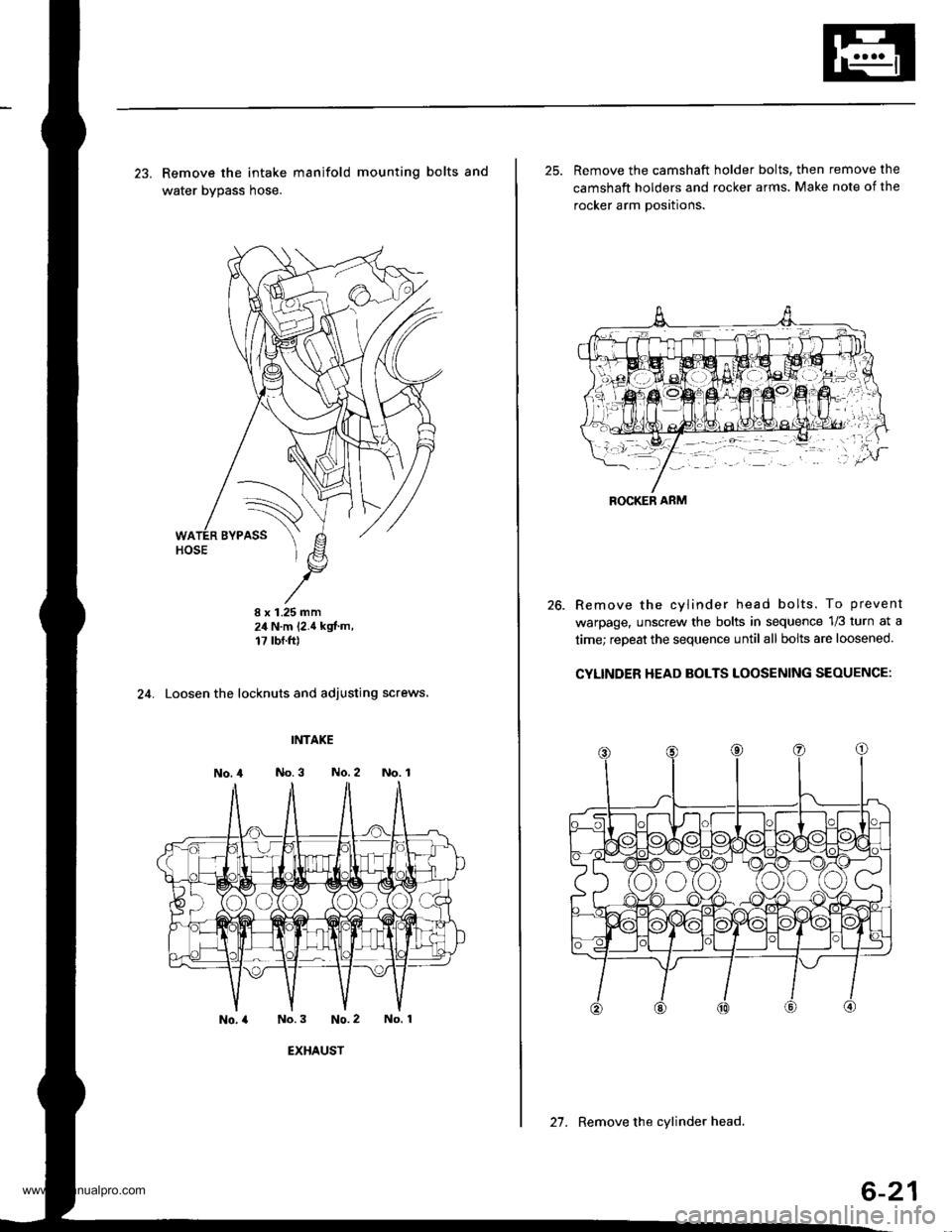
23. Remove the intake manifold mounting bolts and
water bvDass hose.
8 x 1.25 mm2,1 N.m 12.4 kgt.m,17 tbf.ft)
24. Loosen the locknuts and adjusting screws,
INTAKE
No.3 No.2 No. 1
No.3 No.2 No. 1
EXHAUST
No. 4
27. Remove the cylinder head.
6-21
25. Remove the camshaft holder bolts, then remove the
camshaft holders and rocker arms. Make note of the
rocker arm Dositions.
26. Remove the cylinder head bolts. To prevent
warpage, unscrew the bolts in sequence 1/3 turn at a
time; repeat the sequence until all bolts are loosened.
CYLINDER HEAD BOLTS LOOSENING SEOUENCE:
ROCKER ARM
www.emanualpro.com
Page 143 of 1395
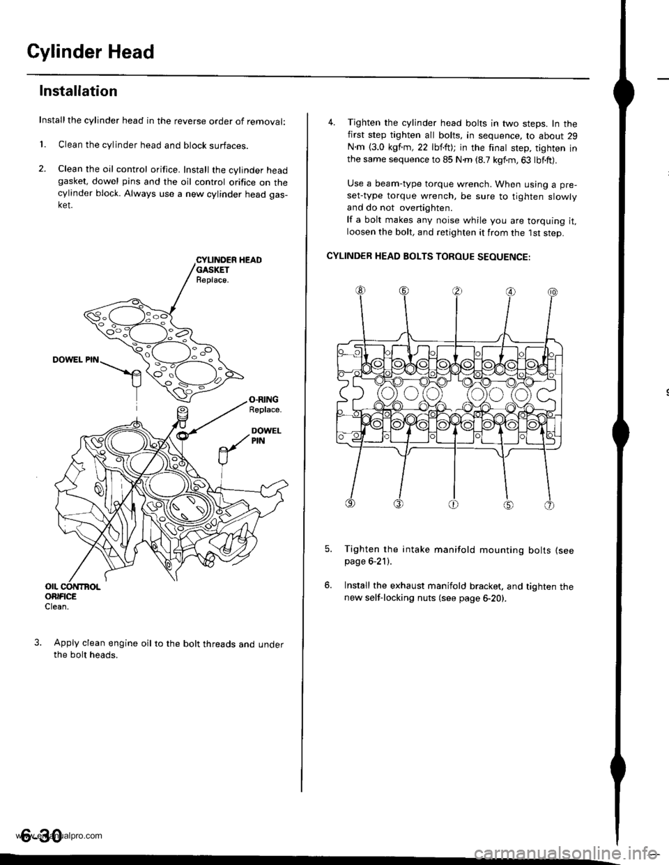
Cylinder Head
Installation
Installthe cylinder head in the reverse order of removal:
1. Clean the cylinder head and block surfaces.
2. Clean the oil control orifice. Install the cylinder headgasket, dowel pins and the oil control orifice on thecylinder block. Always use a new cylinder head gas-ket.
CYLII{DER HEADGASKETR€place.
DOWEL PIN
O.RINGRoplace.
DOWELPIN
OIL CONTBOLORIFICEClean.
Apply clean engine oil to the bolt threads and underthe bolt heads.
4. Tighten the cylinder head bolts in two steps. In thefirst step tighten all bolts, in sequence, to about 29
N.m {3.0 kgf.m,22 lbf.ft); in the finat step, tighten inthe same sequence to 85 N.m (8.7 kgf.m,63 lbf.ft).
Use a beam-type torque wrench. When using a pre-
set-type torque wrench, be sure to tighten slowly
and do not overtighten.
lf a bolt makes any noise while you are torquing it,loosen the bolt, and retighten it from the 1st step.
CYLINDER HEAD BOLTS TOROUE SEOUENCE:
Tighten the intake manifold mounting bolts (see
page 6-21).
Install the exhaust manifold bracket. and tighten thenew self-locking nuts (see page 6-20).
6-30
www.emanualpro.com
Page 351 of 1395
ldle Control System
System Description
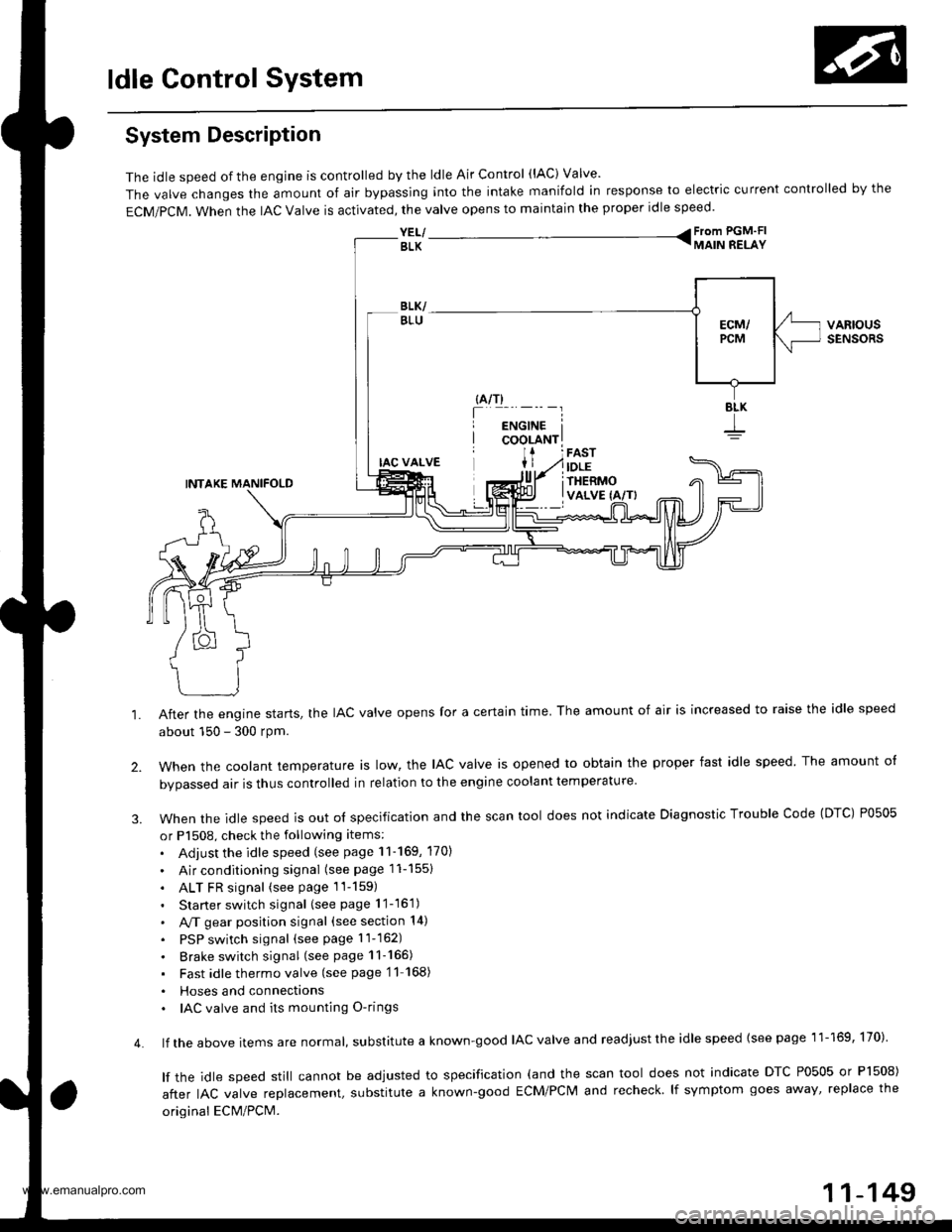
The idle speed of the engjne is controlled by the ldle Air Control (lAC) Valve'
The valve changes the amount of air bypassing into the intake manifold in response to electric current controlled by the
ECM/PCM. When the lAc valve is activated, the valve opens to maintain the proper idle speed.
YEL/ From PGM'FI
BLK TMAIN RELAY
VARIOUSSENSORS
4.
IAC VALVE
INTAKE MANIFOLD
After the engine starts, the IAC valve opens for a certain time. The amount of air is increased to raise the idle speed
about 150 - 300 rpm.
when the cootant temperature ts row, the lAc valve is opened to obtain the proper fast idle speed The amount o{
bvoassed air is thus controlled in relation to the engine coolant temperature
When the idle speed is out o{ specification and the scan tool does not indicate Diagnostic Trouble Code (DTC) P0505
or P1508, check the following items:
. Adjust the idle speed (see page 11-169, 170)
. Air conditioning signal (seepagell-1551
. ALT FR signal (see page 1l-159)
. Starter switch signal (see page 11-16'1)
. A,/T gear position signal (see section 14)
. PSP switch signal (seepagell-162)
. Brake switch signal (see page 11-165)
. Fast idlethermovalve (see page'11 168)
. Hoses and connecttons. IAC valve and its mounting O-rings
lf the above items are normat, suDslitute a known-good IAC valve and readjust the idle speed {see page 11-169, 170)
lf the idle speed still cannot be adjusted to specification (and the scan tool does not indicate DTC P0505 or Pl508)
after IAC valve reolacement, substitute a known-good ECM/PCM and recheck lf symptom goes away' replace the
original ECM/PCM.
11-149
www.emanualpro.com
Page 385 of 1395
Fuel Pump
Testing
lf you suspect a problem with the fuel pump, check that
the fuel pump actually runs; when it is oN (ll), you will
hear some noise if you hold your ear to the fuel fill port
with the fuel fill cap removed. The fuel pump should run
for two seconds when ignition switch is first turned ON (ll).
lf the fuel pump does not make noise, check it as follows:
1. Fold the left rear seat cushion forward, and remove
the base frame cover (see section 20).
2, Remove the access panel from the floor.
3. Make sure the ignition switch is OFF, then discon-
nect the fuel pumP 5P connector.
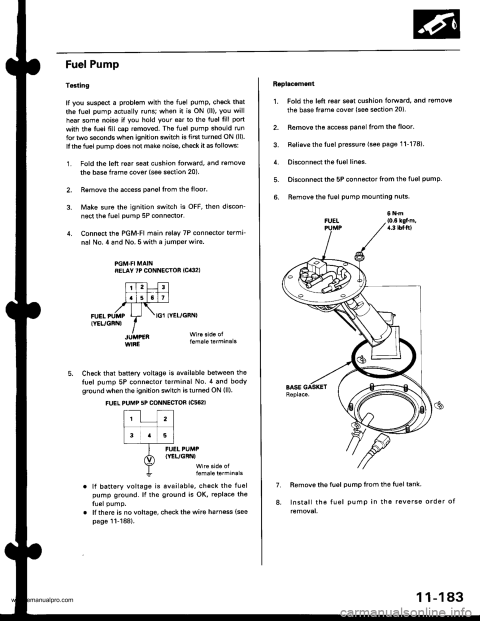
4. Connect the PGM-FI main relay 7P connector termr-
nal No. 4 and No, 5 with a jumper wire.
PGM.FI MAINRELAY 7P CONNECTOR (Cit:}2l
I'TtlJilt f -r'-r ll.l5l517l,frTt-,at\FUEL pUMp Lr- . tcl tyEL/cRNl
rYEL/cRNl IIJUMPER Wir€ side of
WIRE female terminals
5. Check that battery voltage is available between the
fuel pump 5P connector terminal No. 4 and body
ground when the ignition switch is turned ON (ll).
FUEL PUMP 5P CONNECTOR {C562}
12
3a5
lf battery voltage is available, check the fuel
pump ground. lf the ground is OK, replace the
fuel oumo.
lf there is no voltage, check the wire harness (see
page 11-188).
FUEL PUMP(YEL/GRNI
wire side offemale terminals
Raplac6mont
1. Fold the left rear seat cushion forward, and remove
the base frame cover (see section 20).
2. Remove the access panel from the floor.
3, Relieve the fuel pressure (see page 11-178).
4. Disconnect the fuel lines.
5. Disconnect the 5P connector from the fuel pump.
6. Remove the fuel pump mounting nuts.
7. Remove the fuel pump from the fuel tank.
Install the fuel pump in the reverse order of
removal.
8.
11-183
www.emanualpro.com
Page 434 of 1395
Pressure Plate
Removal/lnspection
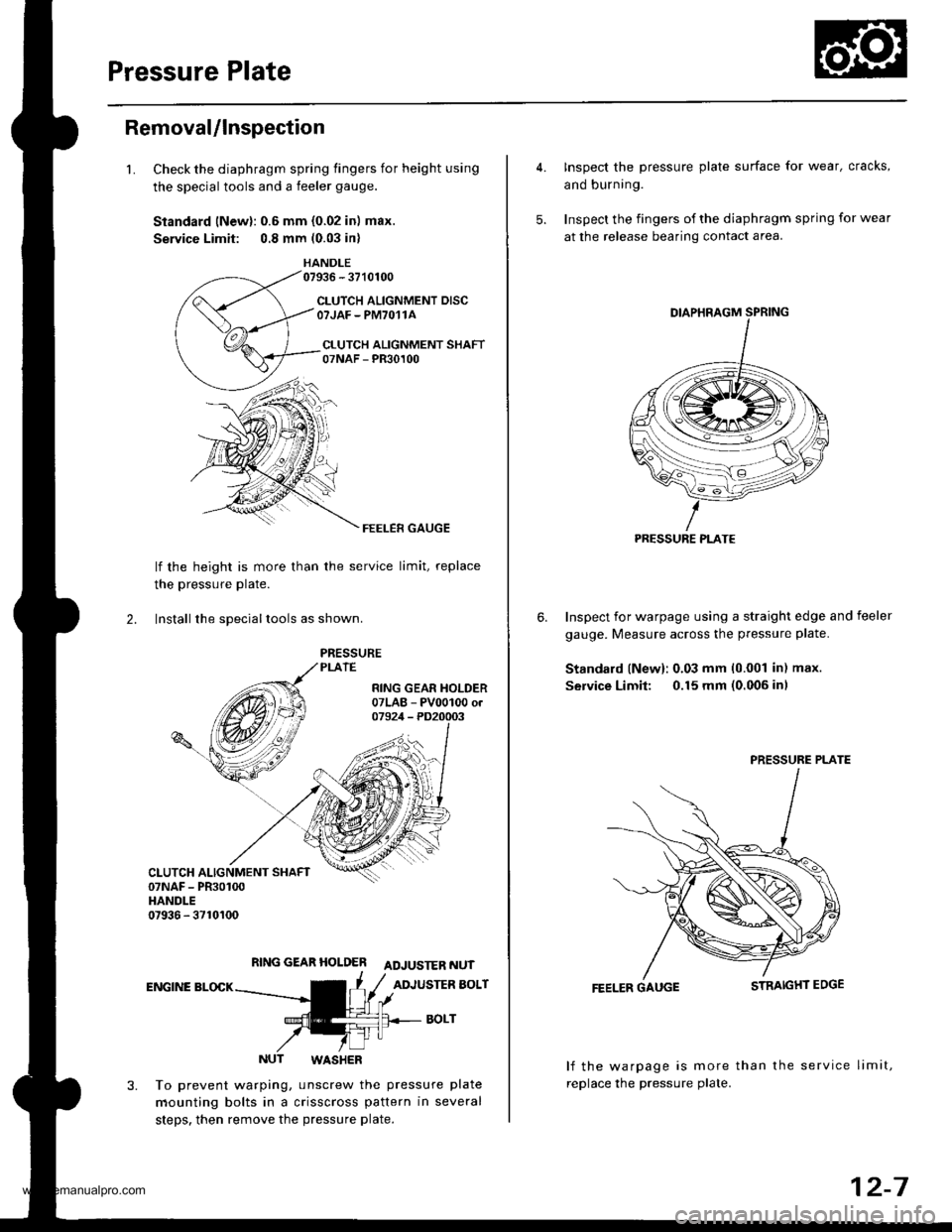
1.Check the diaphragm spring fingers for height using
the special tools and a feeler gauge.
Standard lNewl: 0.6 mm {0.02 in) max.
Service Limit: 0.8 mm (0.03 in)
HANDLE07936 - 3710100
CLUTCH ALIGNMENT DISCOTJAF - PM7O11A
CI.UTCH ALIGNMENT SHAFT07NAF - PR30100
FEELER GAUGE
lf the height is more than
the pressure Plate.
the service limit, replace
2. lnstall the sDeciallools as shown.
RING GEAR HOLDER ADJUSTER NUT
ENGINE BLOCKADJUSTER BOLT
BOLT
NUT WASHER
To prevent warping, unscrew the pressure plate
mounting bolts in a crisscross pattern in several
steps. then remove the pressure plate.
4. Inspect the pressure plate surface for wear, cracks,
and burning.
5. Inspect the fingers of the diaphragm spring for wear
at the release bearing contact area.
Inspect for warpage using a straight edge and feeler
gauge. Measure across the pressure plate.
Standard lNew): 0.03 mm 10.001 in) max.
Service Limit: 0.15 mm (0.006 inl
6.
FEELER GAUGE
lf the warpage is more than the service limit,
replace the pressure plate.
PRESSURE PLATE
PRESSURE PLATE
12-7
www.emanualpro.com
Page 436 of 1395
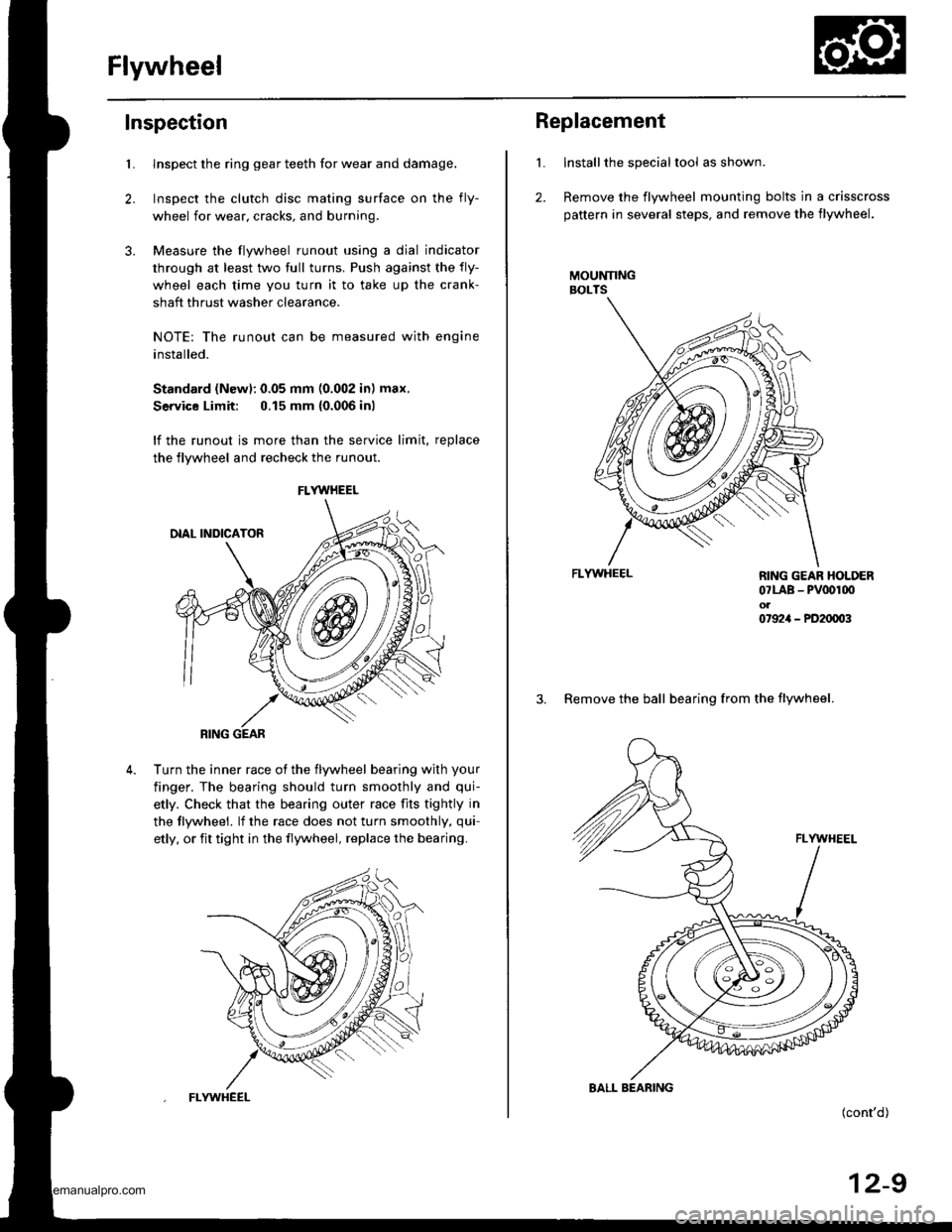
Flywheel
Inspection
2.
3.
Llnspect the ring gear teeth for wear and damage.
Inspect the clutch disc mating surface on the fly-
wheel for wear, cracks, and burning
Measure the flywheel runout using a dial indicator
through at least two full turns. Push against the fly-
wheel each time you turn it to take up the crank-
shaft thrust washer clearance.
NOTE: The runout can be measured with engine
installed.
Standard (Newl: 0.05 mm (0.002 in) max.
Service Limit: 0.15 mm {0.006 inl
lf the runout is more than the service limit, replace
the flywheel and recheck the runout
Turn the inner race ot the flywheel bearing with your
finger. The bearing should turn smoothly and qui-
etly. Check that the bearing outer race fits tightly in
the tlywheel. lf the race does not turn smoothly, qui-
etly, or fit tight in the flywheel, replace the bearing.
FLYWHEEL
RING GEAR
FLYWHEEL
L
2.
Replacement
Installthe special tool as shown.
Remove the flywheel mounting bolts in a crisscross
pattern in several steps, and remove the flywheel.
MOUNNNGBOLTS
FLYWHEEL
(cont'd)
12-9
RING GEAR HOLDER07LAB - PV00r00ol07924 - PD20003
3. Remove the ball bearing from the flywheel.
BALL BEARING
www.emanualpro.com
Page 437 of 1395
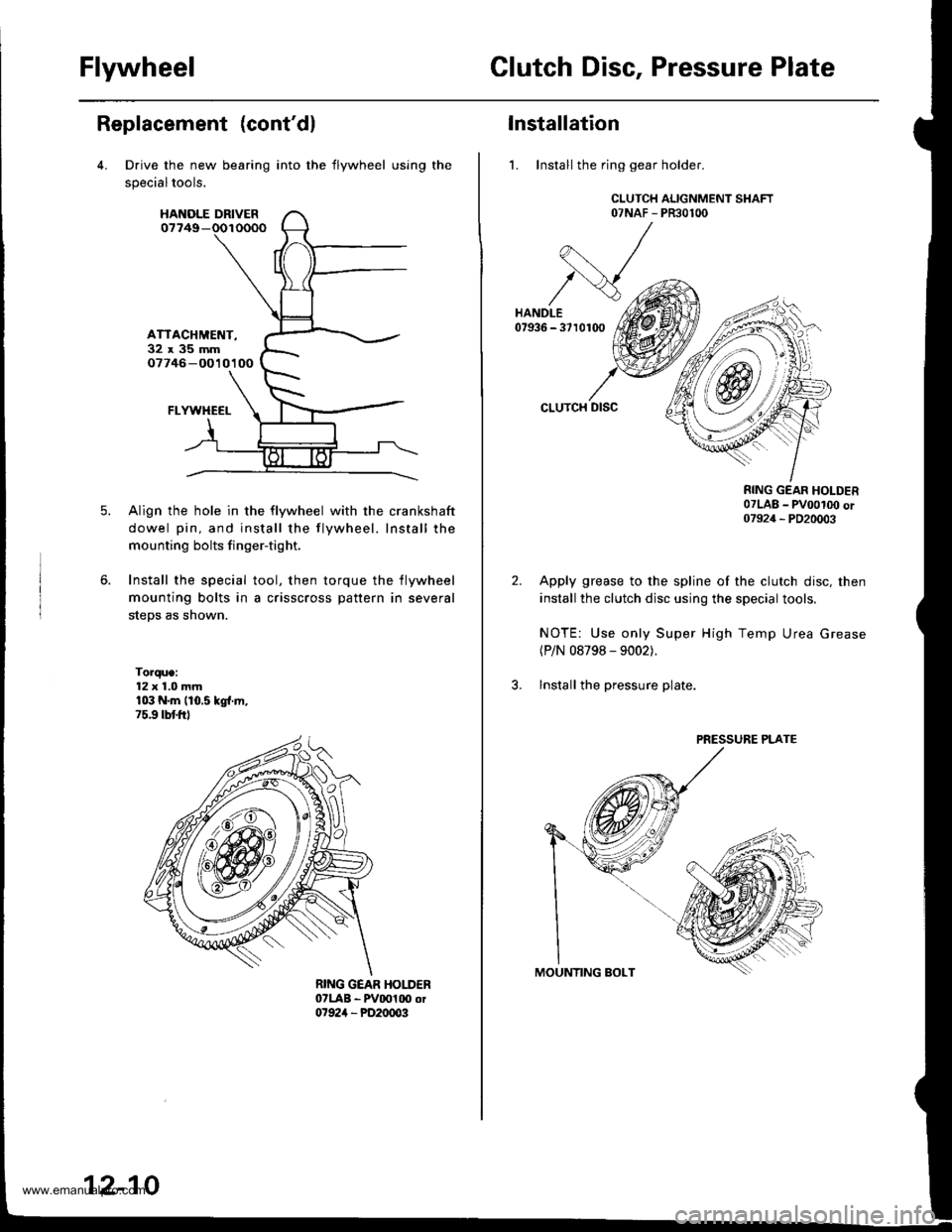
FlywheelClutch Disc, Pressure Plate
Replacement (cont'dl
Drive the new bearing
specialtools.
HANOLE DRIVER07749-
ATTACHMET{T-32x35mm07746 -O010100
FLYWHECI-
Align the hole in the flywheel with the crankshaft
dowel pin, and install the flywheel. Install the
mounting bolts finger-tight.
Install the special tool, then torque the flywheel
mounting bolts in a crisscross pattern in several
steps as shown.
Torque:12 x 1.0 mmr03 N.m (10.5 kgl.ln,75.9 tbtftl
into the flywheel using the
12-10
Installation
1. Install the ring gear holder.
CLUTCH ALIGNMENT SHAFT07NAF - PR30100
CLUTCH DISC
RING GEAR HOLDER07LAB _ pvoot(x) or07924 _ PD20003
Apply grease to the spline of the clutch disc, then
install the clutch disc using the special tools.
NOTE: Use only Super High Temp Urea Grease(P/N 08798 - 9002).
lnstall the pressure plate.
PRESSURE PLATE
www.emanualpro.com