index HONDA CR-V 1997 RD1-RD3 / 1.G User Guide
[x] Cancel search | Manufacturer: HONDA, Model Year: 1997, Model line: CR-V, Model: HONDA CR-V 1997 RD1-RD3 / 1.GPages: 1395, PDF Size: 35.62 MB
Page 173 of 1395
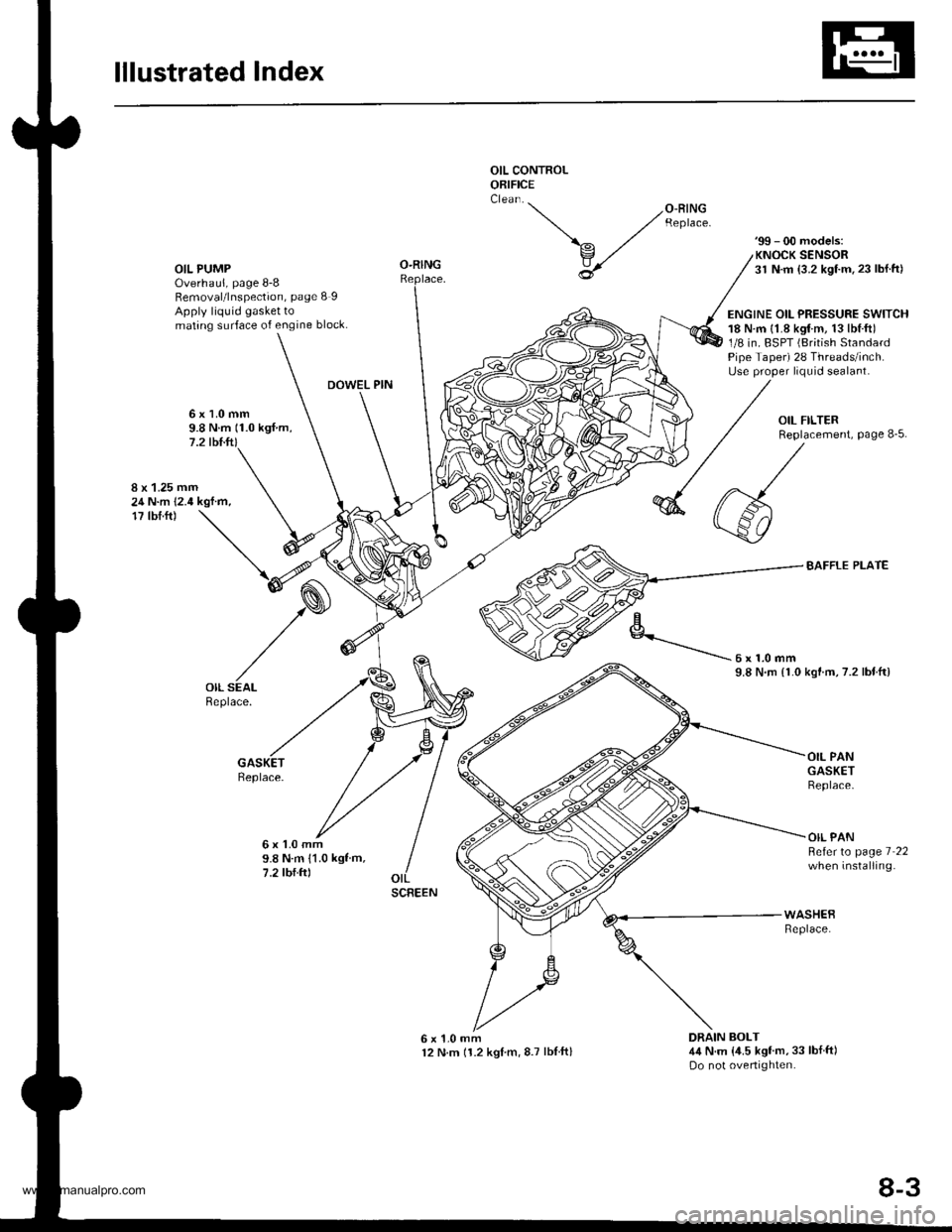
lllustrated Index
OIL CONTROLORIFICE
OIL PUMPOverhaul, page 8-8Removal/lnspection, page 8 IApply liquid gasket tomating surface of engine block.
'99 - 00 models:KNOCK SENSOR31 N.m {3.2 kgf.m.23 lbl.ft)
ENGINE OIL PRESSURE SWITCH18 N.m {1.8 kgtm, 13lbl.ft)1/8 in. BSPT (British StandardPipe Taper) 28 Threads/inch.Use proper liquid sealant.
O-RING
DOWEL PIN
6x1.0mm9.8 N.m (1.0 kgf.m,7.2 tbl.ft)
8 x 1.25 mm24 N.m 12.4 kgf.m,17 tbf.ft)
BAFFLE PLATE
kgtm,7.2 lbtftl
Replace.
6x1.0mm9.8 N.m 11.0 kgf m,7.2 tbf.ftl
OIL PANGASKETReplace.
OIL PANBeferto page 7 22when installing.
6x1.0mm12 N.m 11.2 kglm,8.7 lblftl
WASHEBReplace.
DRAIN BOLT4,1N.m {,1.5 kgf'm,33 lbf ft)Do not overtighten.
'-- /o-RrNG ,/ Reptace.
\^ ./
v,/
U
6x1.0mm9.8 N.rn {1.0
SCREEN
8-3
www.emanualpro.com
Page 189 of 1395
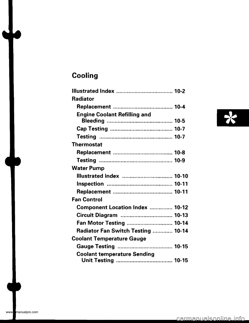
Cooling
f ffustrated Index ........... ..... 1O-2
Radiator
Rep|acement ...........,....,...................... 10-4
Engine Coolant Refilling and
Bleeding ..,.,................. 10-5
Cap Testing .................... 10-7
Testing ......10-7
Thermostat
Rep|acement ....................................... 10-8
Testing ...... 10-9
Water Pump
lllustrated lndex ....,..... .. 10-10
Inspection . 10-1 1
Replacement ....................................,.. 10-1 1
Fan Gontrol
Component Location Index ............... 10-12
Circuit Diagram ............. 10-13
Fan Motor Testing ......... 10-14
Radiator Fan Switch Testing ............. 10-14
Coolant Temperature Gauge
Gauge Testing ............... 10-15
Coolant temperature Sending
Unit Testing ........,....... 10-15
www.emanualpro.com
Page 190 of 1395
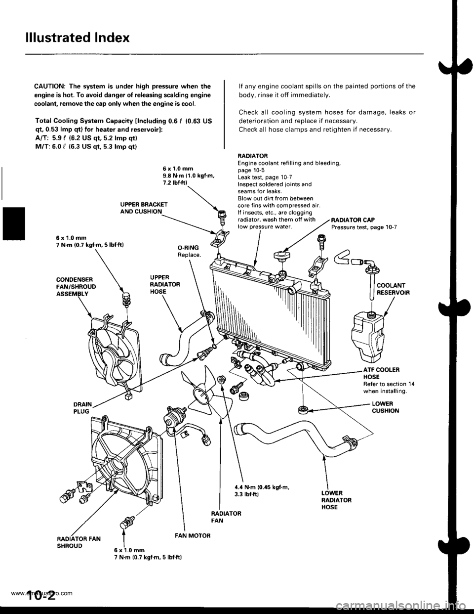
lllustrated Index
CAUTION: The system is under high pressure when the
engine is hot. To avoid danger ol releasing scalding engine
coolant, remove the cap only when the engine is cool.
Total Cooling System Capacity fincluding 0.6 I (0.63 US
qt, 0.53 lmp qt) for heater and reservoirl:
A/T: 5.9 { {6.2 US qt, 5.2 lmp qt)
M/T: 6.0 f (6.3 US $, 5.3 lmp qt)
deterioration and replace if necessar,.
Check all hose clamps and retighten if necessary.
lf any engine coolant spills on the
body, rinse it off immediately.
Check all cooling system hoses
painted portions of the
for damage, leaks or
6x1.0mm9.8 N.m 11.0 kgf.m.1.2 tbl.ftl
RADIATOREngine coolant refilling and bleeding,page 10-5Leak test, page 10 7Inspect soldered joints andseams for leaks.Blow out din from betweencore fins with compressed air.lf insects, etc., are cloggingradiator, wash them off withlow pressure water.RADIATOR CAPPressure test, page 10-7
ATF COOLERHOSEReler to section 14when installing.
LOWERcusHroN
6x1.0mm7 N.m (0.7 kgf.m, 5 lbf ftl
FAN MOTOR
10-2
www.emanualpro.com
Page 198 of 1395
Water Pump
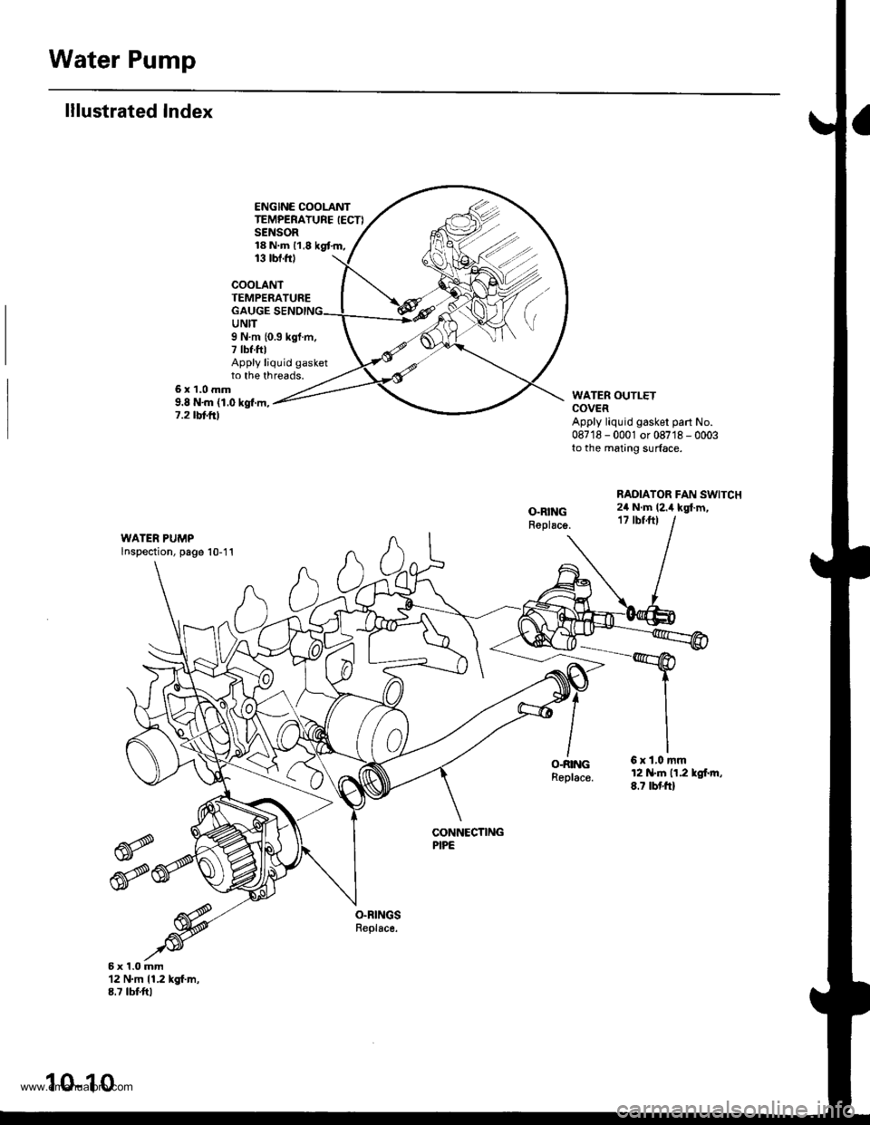
lllustrated Index
ENGINE COOLANTTEMPERATURE IECTISENSOR18 N.m 11,8 kgt.m,13 tbt.ftl
COOLANTTEMPERATUREGAUGEUNIT
6x1.0mm9.8 N'm (1.0 kgf.m,7.2 tbt frl
9 N.m {0.3 kgf.m,7 tbf.fttApply liquid gasketto the threads.
WATER OUTLETCOVERApply liquid gasker part No.087'18 - 0001 or 08718 - 0003to the mating surface.
RADIATOR FAN SWITCH2il N.m (2.i1 kgl.m,17 tbfft)
WATER PUMPlnspection, page 10-11
O-RINGReplac€.
6xl,0mm12 N.tn n.2 lgl.rn,8.7 tbf'ft)
CONNECTINGPIPE
6x1.0mm12 N.m 11.2 kgf.m,8.7 tbtftl
10-10
www.emanualpro.com
Page 200 of 1395
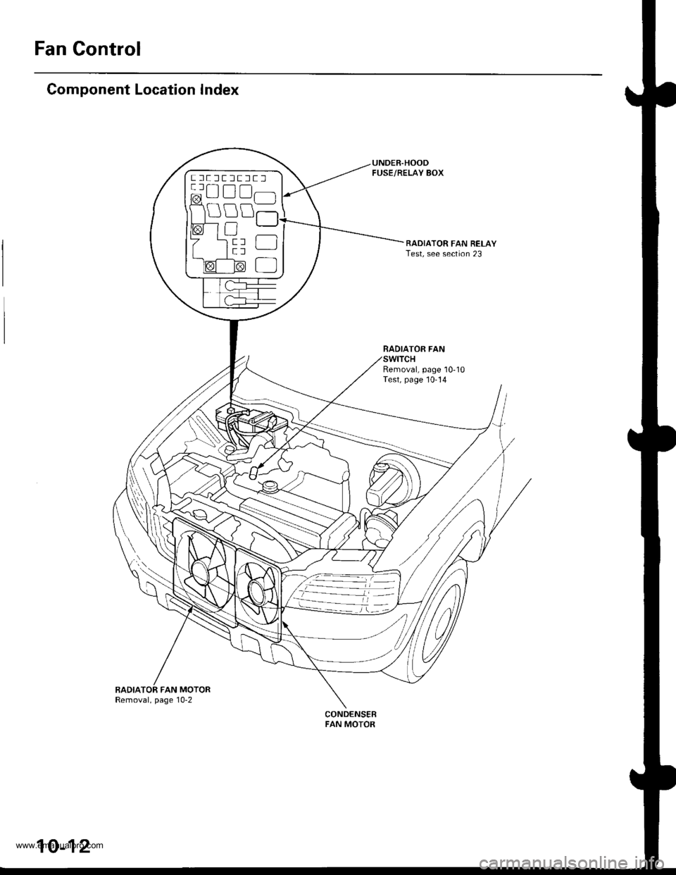
Fan Control
Component Location Index
UNDEB.HOODFUSE/RELAY BOX
RADIATOR FAN RELAYTest, see section 23
BADIATOR FAN
Removal, page 10-10Test, page 10-14
BADIATOR FAN MOTORRemoval, page 10-2
CONDENSERFAN MOTOR
ftflEffltrlt lrt r-1 a-l
@u!lfl]l
10-12
www.emanualpro.com
Page 207 of 1395
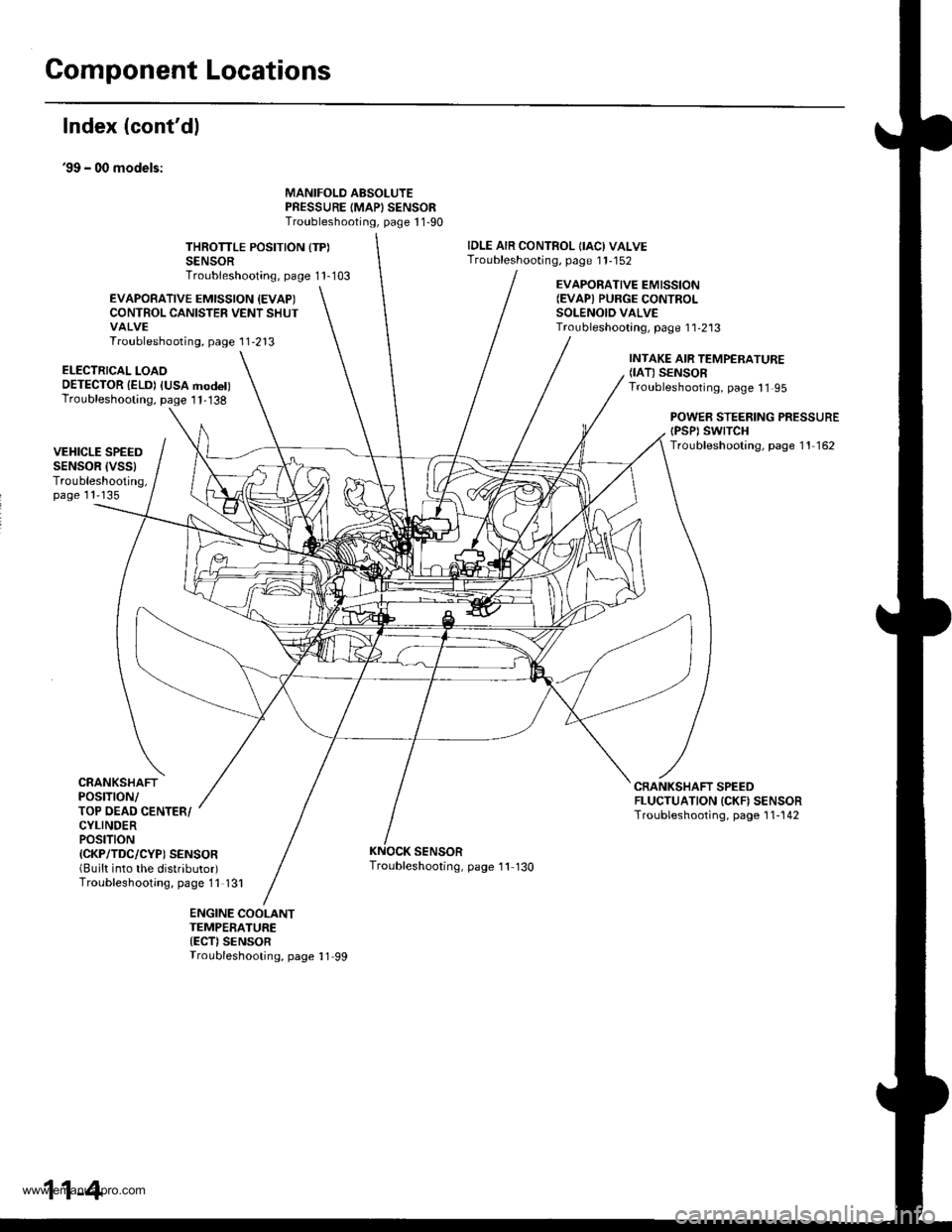
Component Locations
Index (cont'dl
39 - 00 models:
MANIFOLD ABSOLUTEPRESSURE IMAPISENSORTroubleshooting, page 1 1-90
THROTTLE POSITION {TP)SENSORTroubleshooting, page 1 1-103
IDLE AIR CONTROL OACI VALVETroubleshooting, page 1 1-152
EVAPOBATIVE EMISSION {EVAPICONTROL CANISTER VENT SHUTVALVETroubleshooting, page 1 1-213
EVAPORATIVE EMISSION(EVAPI PURGE CONTROI-SOLENOID VALVETroubleshootang, page 1 1-2'13
ELECTRICAL LOAOOETECTOR {ELD) IUSA modet)Troubleshooting, page I 1-138
INTAKE AIR TEMPERATURE(IAT) SENSORTroubleshooting, page 11 95
POWEB STEERING PRESSUREtPsPt swtTcHTroubleshooting, page 11 162VEHICLE SPEEDSENSOR IVSSITroubleshooting,page 11'135
CRANKSHAFTPOSTTTON/TOP OEAD CENTER/CYLINDERPOStTtON{CKP/TDC/CYP) SENSOR(Built into the distributor)Troubleshooting, page 11 131
CRANKSHAFT SPEEDFLUCTUATION ICKN SENSORTroubleshooting, page 1 1-142
SENSORTroubleshooting, page '11 130
ENGINE COOLANTTEMPERATURE{ECT)SENSORTroubleshooting, page 11 99
11-4
www.emanualpro.com
Page 209 of 1395
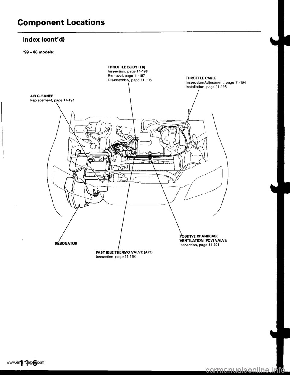
Component Locations
Index {cont'd)
39 - q, models:
THROTTLE BODY ITB)Inspection, page 1 1-196Removal, page 11- 197Disassembly, page 11 198THROTTLE CABLEInspectaon/Adjustment, page 1 1 194Installation, page I l'195
AIR CLEANERR€placomenl, page 1 1-194
CRANKCASEVENTILATION IFCVI VALVElnspection, page 11 201
FAST IDLE THERMO VALVE IA/T)Inspection, page 11'168
1 1-6
www.emanualpro.com
Page 211 of 1395
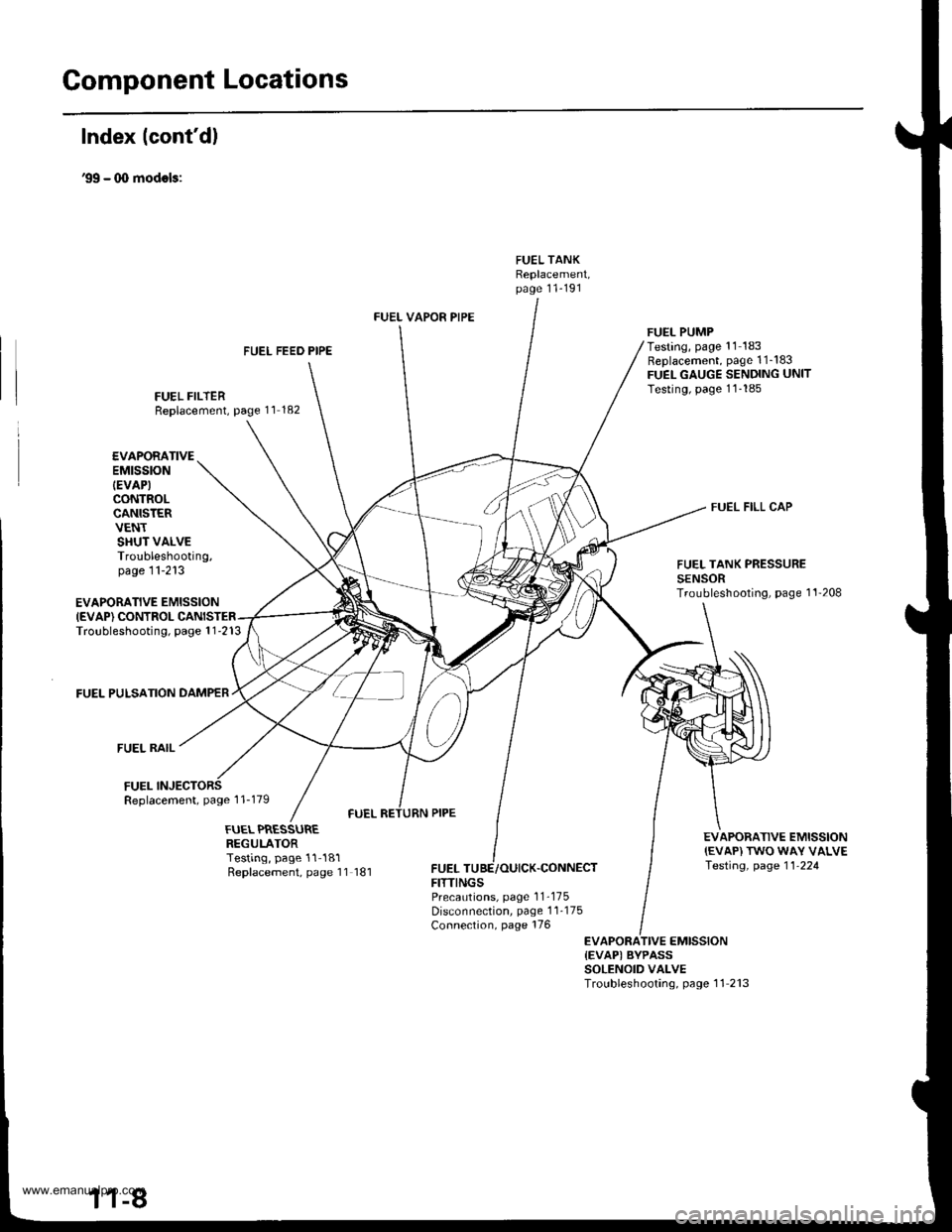
Gomponent Locations
Index lcont'd)
'99 - (X) modols:
FUEL TANKReplacement,page 11-191
FUEL FEED PIPE
FUEL FILTERReplacement, page 11 182
FUEL VAPOR PIPE
FUELFITTINGS
FUEL PUMPTesting, page '11 183Replacement, page 1 1_183FUEL GAUGE SENDING UNITTesting, page 11-185
FUEL FILL CAP
EVAPORATIVE EMISSIONIEVAP) CONTROLTroubleshooting, page 1 1-213
FUEL PULSATION DAMPER
FUEL RAIL
FUELReplacement, page 1 1-179
EVAPORATIVEEMtSStON
IEVAP)CONTROLCANISTERVENTSHUT VALVETroubleshooting,page 11-213FUEL TANK PRESSURESENSORTroubleshooting, page 1'l'208
EVAPORATIVE EMISSION{EVAP) TWO WAY VALVETesting, page 11-224
FUEL PRESSUREREGULATORTesting, page 11-181Replacement, page 11 181,CONNECT
PrecaLrtions, page 1 1-175Disconnection, page 1 1-175Connection, page 176
EVAPORATIVE EMISSION{EVAPI BYPASSSOLENOID VALVETroubleshooting, page 11 213
www.emanualpro.com
Page 430 of 1395
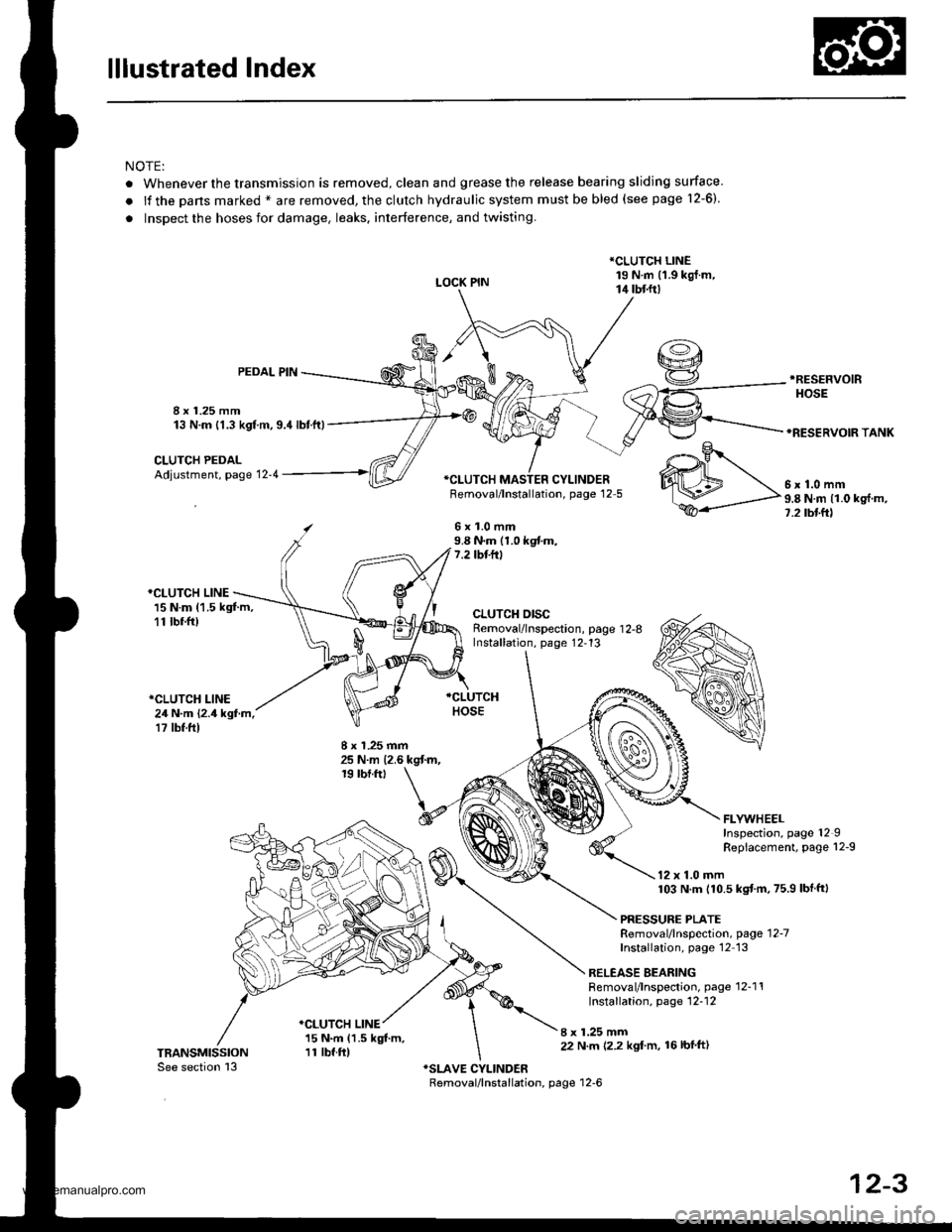
lllustrated Index
NOTE:
. Whenever the transmission is removed, clean and grease the release bearing sliding surface
.lfthepansmarked*areremoved,theclutchhydraulicsystemmustbebled(seepage1\
2-6).
. Inspect the hoses for damage. leaks. interference, and twisting.
LOCK PIN
*CLUTCH LINE19 N.m (1.9 kgj.m,14 tbtft)
8 x 1.25 mm13 N.m {1.3 kgf m,9.4lbtft)
PEDAL PIN.RESEFVOIR
HOSE
*RESERVOIR TANK
CLUTCH PEDALAdjustment, page 12-4*CI-UTCH MASTER CYLINDERFemoval/lnstallation, page 12-5
6x1.0mm9.8 N.m (1.0 kgf.m,7.2 tbf.ft)
*CLUTCH LINE15 N.m (1.5 kgt m,11 tbr.ft)
*CLUTCH LINE24 N.m {2.4 kgf.m,17 tbf.ft)
CLUTCH DISCRemoval/lnspection, page 1 2-8Installation, page 12,13
8 x 1.25 mm25 N.m {2.6 kgt m,19 rbf.ftt
I x 1.25 mm22 N.m 12.2 kgl'm, 16lbfft)
.o-.9r
WM\,".0--
ffi-P"8Nmlloks{m'
FLYWHEELInspection, page 12IRepiacement, page 12-9
12 x 1.0 mm103 N.m (10.5 kgtm,75.9 lbf ftl
PRESSURE PLATERemoval/lnspection, page'12-7
Installation, page'12 13
RELEASE BEARINGRemoval/lnspection, page 12-1'!Installation, page 12-12
*CLUTCH LINE15 N.m (1.5 kgt m,11 tbf.ft)
12-3
www.emanualpro.com
Page 440 of 1395
Manual Transmission
Diff€rential
lndex ...................... ......... 13-38
Backlash Inspestion ..,....,.,.....................,......, 13-38
Final Driven Gear Replacement .................... 13-39
Tapered Roller BearingReplacement ............. 13-39
Bearing Outer Race Replacement ......,.,........ 13-i10
Tapered Roller Bearing PreloadAdiustment ............... 13-il1
Oil Seal Reolacement .................................... 13-/l:}
Transfer Assembly
lllustrated Index ............. 13-il4
Inspection ..,....,.,......,...... 13-46
Disassembly ................... 13-47
Transfer Drive Gear BearingReplacement ...,..................,....................... 13-ilg
Transfer Driven Gear Shaft BearingReplacement .............................................. 13-ilg
Transfer Shaft Disassembly/Reassembly .............. 13-50
Transler Cover A Bearing Outer RaceRep1acement.........,.,.,..........,....,...,.........,., 13-50
Transter Housing Bearing Outer RaceReD1acement.............................................. 13-51
Reassembly ..-............,... 13-52
Mainshaft Bearing/Oil Seal
Beplacement .................. 13-62
Countershaft Bearing
Replacement .,,.,.,., ..,...... 13-63
Mainshaft Thrust Clearance
Adiustment .................... 13-6,1
Transmission Assembly
Reassembly .,.,.,.,..,.,....,., 13-67
fnstaffation .,.,.............,... 13-72
Gearshift Mechanism
Overhaul ................ .........13-17
www.emanualpro.com